> ## Documentation Index
> Fetch the complete documentation index at: https://calcs.com/docs/llms.txt
> Use this file to discover all available pages before exploring further.
# Project Defaults AU NZ
> Every Calcs.com project has a button in the sidebar called 'Project Defaults'. These are a set of default/preset values for the country code in ques...
# Background
Every Calcs.com project has a button in the sidebar called 'Project Defaults'. These are a set of default/preset values for the country code in question.
They are carried through to every new calculation that is created. The purpose of this guide is to clarify the use of these defaults, and which calculators are impacted by each option.
You can still override any of these defaults in a specific calculator by selecting the field in question and manually typing over it. These defaults are purely to save you time, and you don't need to use them if you don't want to. If you copy a project, any project defaults will be copied along with the calculations.
The main sections in Project Defaults are:
1. Building Site
2. Building geometry (e.g. beam spacings, storey heights, roof slope)
3. Design criteria / Load Combinations (e.g. default deflection limits, design code)
4. Default Loads (e.g. default roof, floor, wall & window loads)
5. Load Cases (e.g. standards based, custom)
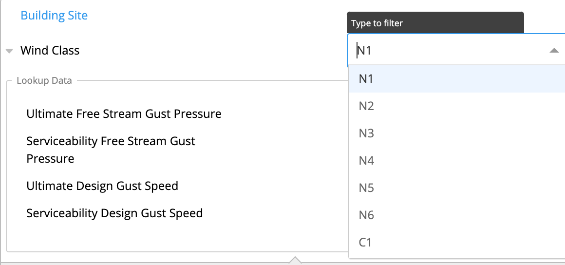
## 1(A) Wind Class
The wind class obtains the relevant gust pressures from AS 4055:2012 Cl 3.3 and gust wind speeds from Table 2.1(A-B). These values are then used in the Wind Load section of various calculators.
| AFFECTED CALCULATORS |
| ------------------------------------ |
| Timber beam |
| Steel beam |
| Beam Analysis with Load Combinations |
| Cold-Formed Steel Beam |
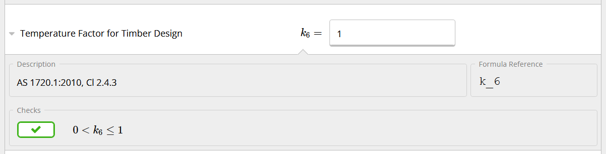
## 1(B) Temperature Factor for Timber Design
In the design of timber structures, this factor is used as a default temperature factor.
| AFFECTED CALCULATORS |
| --------------------------- |
| Timber beam / Column |
| Timber Member (Design Only) |
# 2. Building Geometry
## 2(A) Number of Stories:
Where 2 or more stories, additional options will be provided for "Lower Floor" heights as well as "Top Floor". Note this is typically used with the "CalcsCAD" tool only.

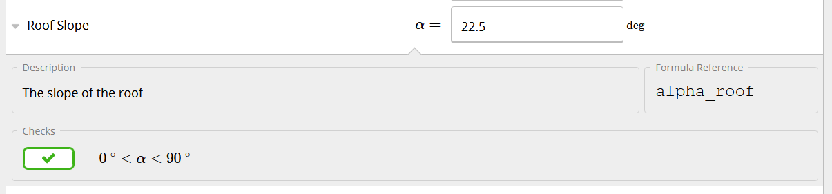
## 2(B) Roof Slope:
The slope of the roof is set on all calculators for design of roof beams, and for the beam and wind analysis calculators. This angle CAN be changed in individual rafter calculators if roof slopes differ through out the project.
| AFFECTED CALCULATORS |
| -------------------------------------------------- |
| Wind Loads (AS/NZS 1170.2) Calculator - Roof Pitch |
| Framing |
| Beam analysis with Load Combinations |
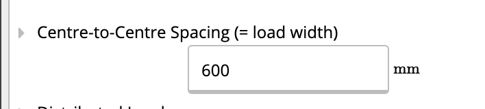
## 2(C) Rafter / Joist Spacing
Spacings are used to calculate default distributed loads in rafters and joists. Refer to article [170-what-is-tributary-width](/docs/learn_calcs/basics/what_is_tributary_width_) for details about how distributed loads are calculated.

*Quick Tip: Did you know that rafters or joists may be linked into other beams (e.g. floor bearer) as a line load? This means you only have to create a single rafter / joist and then Calcs.com will use the spacing to regularly space the reactions. Refer for details [24-linking-reactions-between-beams-and-columns-load-path-tracking](/docs/learn_calcs/advanced_tricks/linking_loads_and_reactions_between_calculators__load_path_tracking_). Of course the values may be overridden within each calculator. See example from the "Steel Beam" calculator:*
# **
| AFFECTED CALCULATORS |
| ----------------------------------------------------------------------------------------------------- |
| Wind Loads Calculator - Roof Angle |
| Steel beam |
| Timber Beam (Rafter, Roof Bearer, Underpurlin, Verandah Beam, Hanging Beam, Ceiling Joist) |
| Cold-Formed Steel Beam (Rafter, Ceiling Joist, Hanging Beam, Verandah Beam, Underpurlin, Roof Bearer) |
| Beam Analysis with Load Combinations |
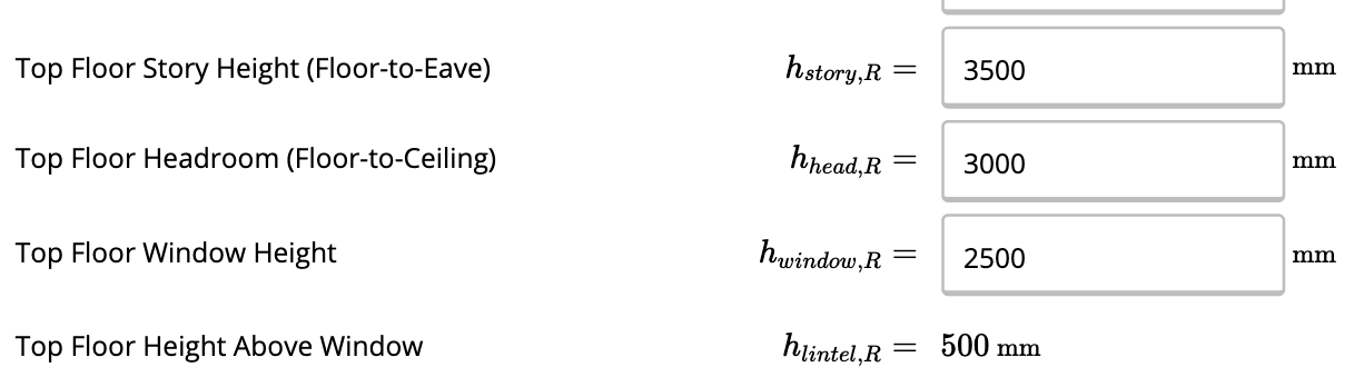
## 2(D) Story Height / Headroom / Roof Beam Depth:
Default heights for most columns (depends on if column is part of a typical light framing or heavy framing system).
| AFFECTED CALCULATORS |
| ----------------------------------------------------- |
| Steel Column (Interior/Perimeter/Corner Multi-Storey) |
| Framing Tool |
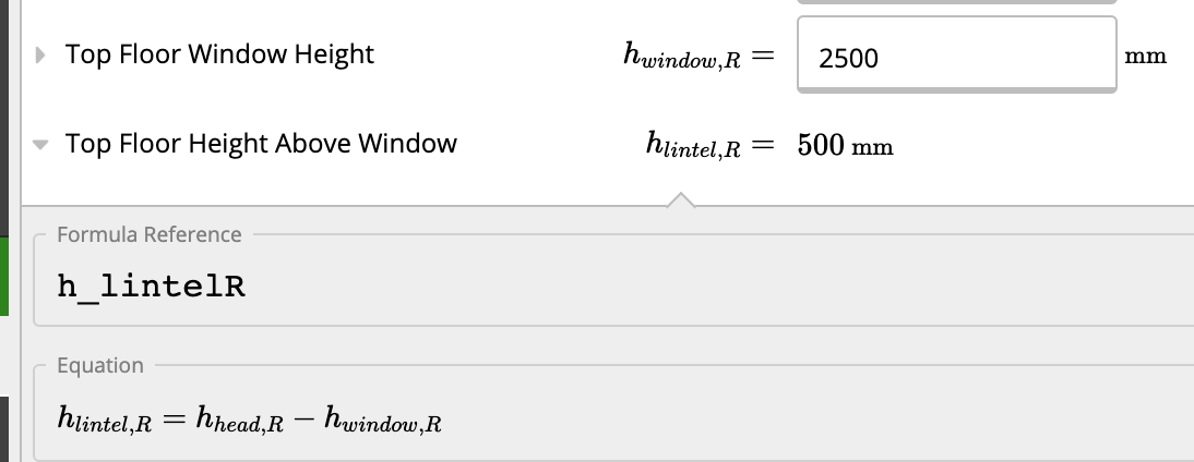
## 2(E) Window Height & Lintel Height:
Tributary width for distributed wall loads.
| AFFECTED CALCULATORS |
| ------------------------------------------- |
| Wall Analysis (Wall under Floor Lintel) |
| Timber Beam (Roof Lintel) |
| Steel Beam (Roof Lintel) |
| Cold-Formed Steel Beam (Roof Lintel) |
| Beam Analysis with Load Cases (Roof Lintel) |
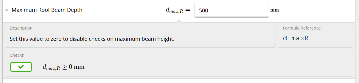
## 2(F) Maximum Roof Beam Depth:
Does your structure have space constraints? Calcs.com will check the depth of your beam, and compare it with the *Maximum Roof Beam Depth* set below.\
| AFFECTED CALCULATORS |
| --------------------------------------------------------------------------------------------------------------------- |
| Wind Loads Calculator - Roof Angle |
| Steel beam |
| Timber Beam (Rafter, Roof Bearer, Underpurlin, Verandah Beam, Hanging Beam, Ceiling Joist) |
| Cold-Formed Steel Beam (Rafter, Ceiling Joist, Hanging Beam, Strutting Beam, Verandah Beam, Underpurlin, Roof Bearer) |
| Beam Analysis with Load Combinations |
# 3. Design Criteria / Load Cases
## 3(A) Deflection Criteria:
Deflection limits may be set that will be defaulted in all calculators where applicable.
Deflection limits must be changed within the individual templates. A hard limit is provided in the Project Defaults which overrides any span limits, which may be also be set.

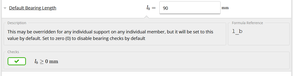
## 3(B) Default Bearing Length:
*A* bearing check is completed for beams. This length is along the length of the beam (i.e. length of supporting member/column).
| AFFECTED CALCULATORS |
| ---------------------------------------------------------------------------------------------------------------------------------------------------------------------- |
| Timber beam |
| Steel beam |
| Cold-Formed Steel Beam
 |
# 4. Default Loads
## 4(A) Roof and Ceiling Loads:
**Roof**
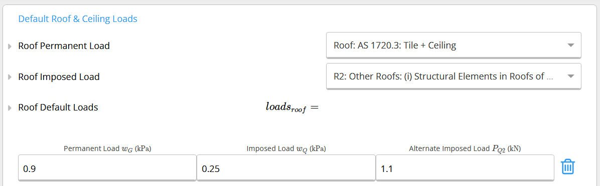
Roof Default Load Table is dynamically set based on the selection of criteria for "Roof Permanent" and "Roof Imposed" Load selections. The following calculation types import these default loads (Timber / Steel / CFS Beams).
The character of Imposed Load is used to set the load factors based on the expected duration (e.g. short-term, medium-term, long-term) of the applied loads.
| AFFECTED CALCULATORS |
| ------------------------------------------------------------------------------------------------------------- |
| Steel Beam & Column (Rafter, Verandah Beam, Underpurlin, Roof Bearer, Roof Lintel Floor Bearer, Floor Lintel) |
| Wood Beam & Column (Rafter, Verandah Beam, Underpurlin, Roof Bearer, Roof Lintel Floor Bearer, Floor Lintel) |
| Concrete Beam & Column |
| Cold Form Steel Beam |
**Ceiling**
Where the ceiling applies a dead load to hanging beams, this permanent load is applied by default to the calculator.\

| AFFECTED CALCULATORS |
| ---------------------------------------------------- |
| Steel Beam (Hanging Beam, Ceiling Joist) |
| Cold Formed Steel Beam (Hanging Beam, Ceiling Joist) |
| Timber Beam (Hanging Beam, Ceiling Joist) |
## 4(B) Floor
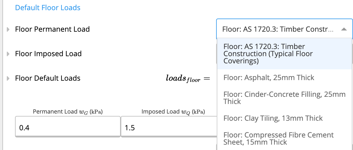
Floors have default area loads depending on the structures' intended use.\
The "Live Load Selection" is used to set the "Default Floor Loads" details in the dropdown menu.
| AFFECTED CALCULATORS |
| ------------------------------------ |
| Beam Analysis with Load Combinations |
| Steel Beam |
| Timber Beam |
| Cold Formed Steel Beam
|
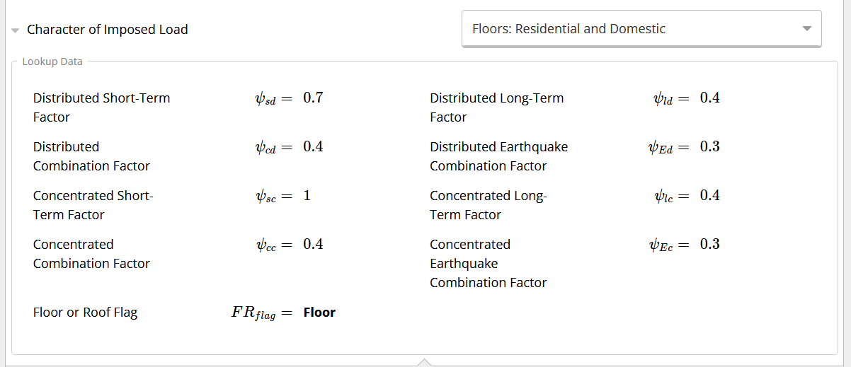
The character of Imposed Load is used to set the load factors based on the expected duration (e.g. short-term, medium-term, long-term) of the applied loads.
## 4(C) Wall & Window
**Wall**\
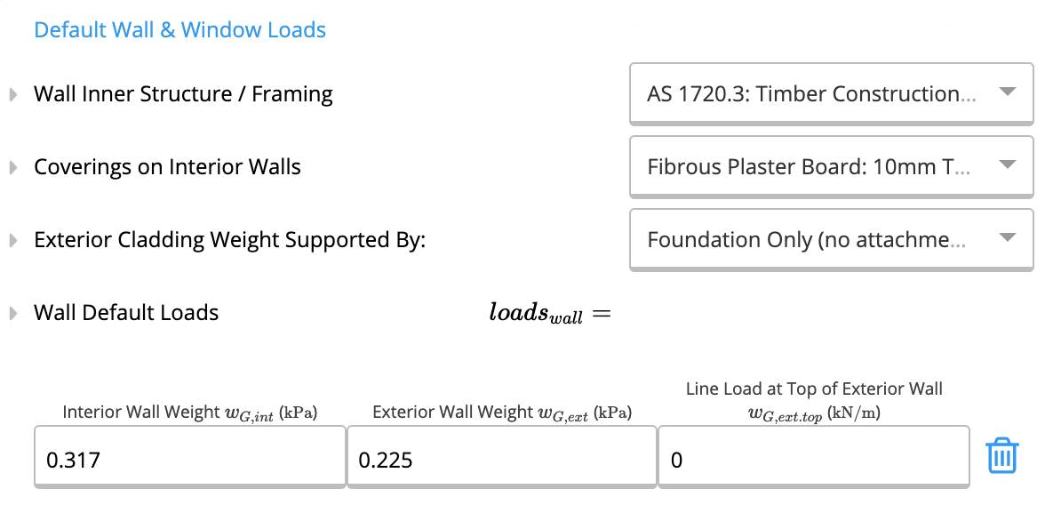
Wall loads are automatically defaulted based on the various selectors at the top of the section.
When used in a calculator, the wall weight below is multiplied by height of wall above the structure (e.g full height wall for floor headers) and entered as a Distributed Load.
The wall framing loads are selected from AS 1720.3:2016, Table 3.3.2.2(A).\
The coverings on internal wall loads are selected from AS/NZS 1170.1:2002, Table A2
The wall weights are determined by taking the weight of covering each face as well as the weight of the wall
**Window**\
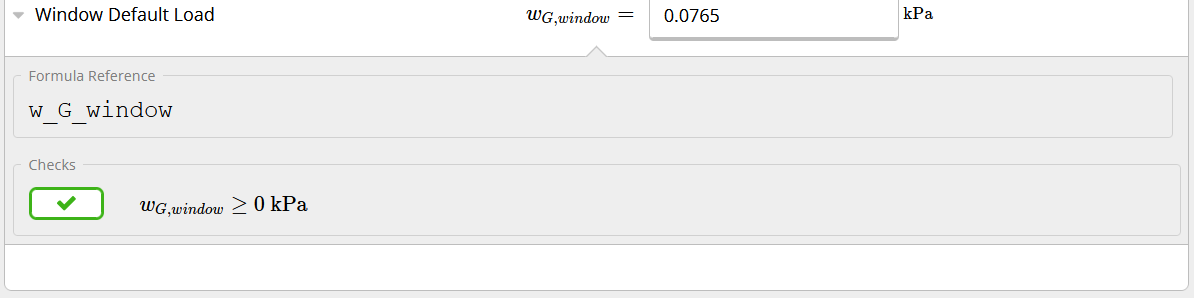
The window area load can be manually set below.\
When used in the Wall Analysis with Load Combinations calculator, the window weight is added to the Self-weight of the structure and may be overridden in the "SW\_Window" input.
## 4(C) Default Railing Property
This is used within the Wall Analysis (Railing) calculator. It is used to set the height of the wall that affects its self-weight.\

# 5. Load Cases
## 5(A) Strength Load Cases
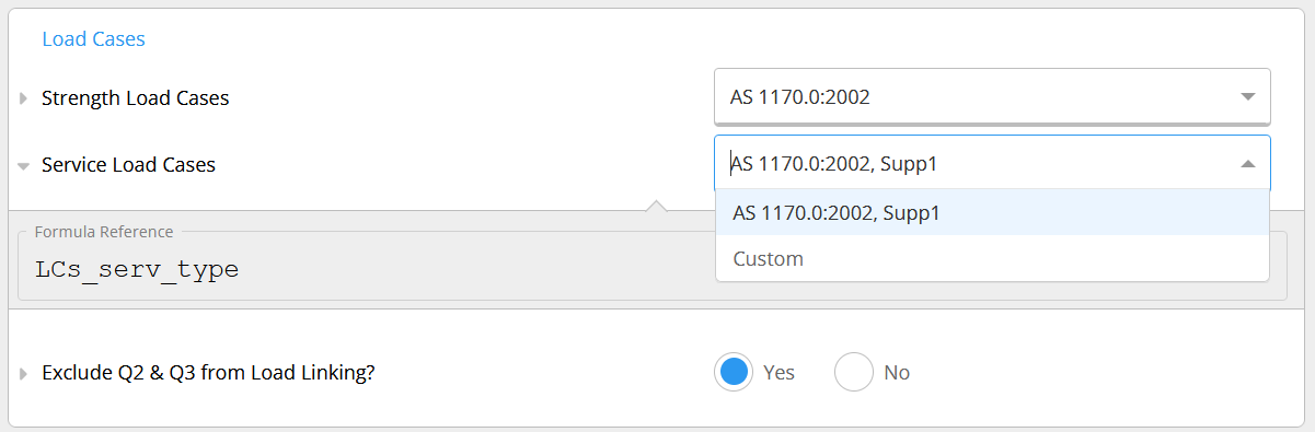
This calculator provides a choice of standards/clauses to use to determine load combinations. You may also select "Custom load combinations" at the bottom of the drop downs and enter custom combinations. Refer article: [141-change-or-create-custom-load-combinations](/docs/learn_calcs/advanced_tricks/change_or_create_custom_load_combinations)
A range of AS 1170 load combinations standards are provided for Strength and Serviceability. These affect the load combinations in all design calculators (e.g. Timber & Steel Beam/Column). Why would you want to set custom combinations?
* Does your company design to more strict combinations than the code requires?
* Does Calcs.com not provide your local state / area code.
*Quick Tip: Did you know that you can create a template project with custom load combinations and duplicate from there instead of create new project defaults each time.*
Each calculation has "alternative" live load combinations, which are not intended to be applied at the same time (e.g. during construction imposed load vs post-construction residential loads). These are represented by Q, Q2 and Q3. When linking loads, you can choose to only transfer through the main load (i.e. the alternative construction load does not need to be applied to others part of the structure).
Generally this load shouldn’t actually be linked through the load path in the building - it should just be an alternate load for individual members only. Select “Yes” here to exclude these loads from all load linking throughout this project.
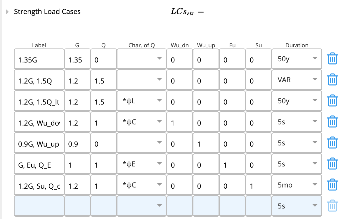
When selecting Custom combinations, a table of combinations is given. For timber calculations, an additional "Duration" column is used that modifies the strength properties of the timber.
\----
Congratulations! You've reached the end of this guide.
# Appendix: Wall & Window Default Loads in Detail
This appendix expands on section **4(C) Wall & Window** above. It clarifies exactly how the default wall and window loads are derived, which calculators they flow into, and how to override them when your project deviates from the standard assumptions. The original 4(C) description still applies - this section is supplementary detail.
## How wall default loads are built
The wall weight shown in the Project Defaults is **not a single typed value**. It is dynamically composed from three layers, each driven by a selector at the top of the Wall block:
1. **Wall framing** - permanent load of the structural studs/plates, taken from **AS 1720.3:2016, Table 3.3.2.2(A)** for timber framing systems. The framing selection (e.g. 90 mm stud at 600 mm centres) sets the kPa contribution.
2. **External covering** - permanent load of the cladding on the exterior face (e.g. weatherboard, brick veneer, fibre cement, render on masonry). Values are taken from **AS/NZS 1170.1:2002, Table A2**.
3. **Internal covering** - permanent load of the lining on the interior face (e.g. plasterboard, fibre cement sheet). Also taken from **AS/NZS 1170.1:2002, Table A2**.
The reported wall weight is the sum of these three contributions, expressed as a load per unit wall area (kPa). When a calculator imports the default, it multiplies this kPa value by the **wall height above the supporting structure** (e.g. full storey height for a floor lintel) and applies the result as a Distributed Load on the beam.
| Selector | Source standard | Driven by |
| ----------------- | ------------------------------- | --------------------- |
| Wall framing | AS 1720.3:2016 Table 3.3.2.2(A) | Stud size and spacing |
| External covering | AS/NZS 1170.1:2002 Table A2 | Cladding type |
| Internal covering | AS/NZS 1170.1:2002 Table A2 | Lining type |
## How window default loads are used
The window default is entered as a single area load (kPa) representing the self-weight of glazing plus frame. It is used in two ways:
* In the **Wall Analysis with Load Combinations** calculator, the window kPa is multiplied by the window area within the wall panel and added to the self-weight of the structure. The combined value appears in the `SW_Window` input and can be typed over directly inside the calculator if your specific window deviates from the project default.
* In **Floor Lintel** and **Roof Lintel** calculators where a window sits in the wall above the lintel, the window load is included in the tributary wall weight applied to the lintel as a distributed load.
If your project mixes window types (e.g. standard double-glazed units in the main rooms and a single heavy fixed glass panel on a feature wall), set the project default to the most common type and override the `SW_Window` input on the calculators that use the heavier glazing.
## Which calculators read these defaults
Both Wall and Window defaults feed into the following AU/NZ calculators automatically. The values can be overridden inside any individual calculator without affecting the project default.
| AFFECTED CALCULATORS |
| --------------------------------------------------------- |
| Wall Analysis (Wall under Floor Lintel) |
| Wall Analysis (Railing) |
| Timber Beam (Floor Lintel, Roof Lintel) |
| Steel Beam (Floor Lintel, Roof Lintel) |
| Cold-Formed Steel Beam (Floor Lintel, Roof Lintel) |
| Beam Analysis with Load Cases (Floor Lintel, Roof Lintel) |
## Overriding the defaults
You have three escalating ways to deviate from the AU/NZ Wall & Window defaults:
1. **One field in one calculator** - click the field in the calculator (e.g. the distributed wall load on a Floor Lintel) and type the new value. Only that calculator is affected.
2. **All calculators in one project** - open Project Defaults and change the Wall framing, External covering, Internal covering, or Window kPa value. Every new calculator created in the project picks up the new value; existing calculators continue to use the value they were created with unless you re-link them.
3. **All future projects** - change your **default building standard** at the account level. See [How to Change Your Default Building Standard](/docs/account_admin/user_management/how_to_change_your_default_building_standard).
### Related links
* [Change or Create Custom Load Combinations](/docs/learn_calcs/advanced_tricks/change_or_create_custom_load_combinations)
* [How Project Defaults Work](/docs/learn_calcs/faq/how_project_defaults_work)
* [What is Tributary Width?](/docs/learn_calcs/basics/what_is_tributary_width_)