> ## Documentation Index
> Fetch the complete documentation index at: https://calcs.com/docs/llms.txt
> Use this file to discover all available pages before exploring further.
# How to Create and Use a Custom Section in the Custom Truss Analysis
> Learn how to build a custom truss layout, define member types, create a custom cross-section, and link it into the Custom Truss Analysis calculator.
## Overview
This guide walks you through how to:
* Create a **custom truss layout**
* Define **FEA nodes** and **elements**
* Assign **member types**
* Create a **custom cross-section**
* Link that cross-section into the truss model
Watch through our example that uses the **AU calculators**, note the workflow is the identical for **US calculators**, since both share similar functionality.
***
## Step 1 — Start a Truss Analysis Wizard
1. Open the **Truss Analysis Wizard**.
2. You’ll see a list of predefined truss types.
If your truss does **not** match a standard pattern, you can switch to a fully customizable layout.
***
## Step 2 — Switch to *Custom Truss*
1. In the **Truss Type** dropdown, scroll down and select **Custom Truss**.
2. A default placeholder truss will appear.
3. Scroll down to the **Custom Truss Definition** section.
This is where you manually define:
* FEA nodes (coordinates)
* Elements connecting those nodes
* Member types assigned to each element (these members correspond to the member selection, this can be customized as well. We will go through this later in the article.)
***
## Step 3 — Add Custom Nodes
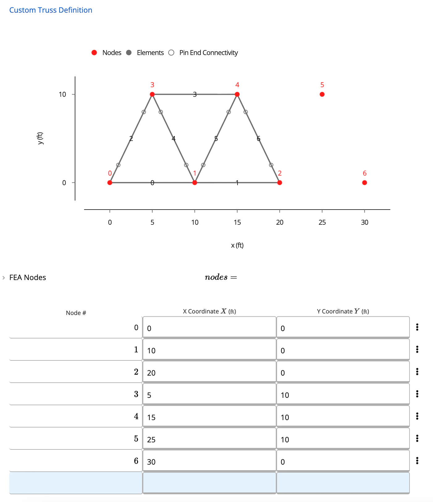
For example, in the **FEA** **Nodes** table:
1. Add a new node at **(25, 10)**
2. Add another node at **(30, 0)**
You can continue adding or removing as many nodes as your geometry requires. Your design can get as simple or complex as you need it to be!
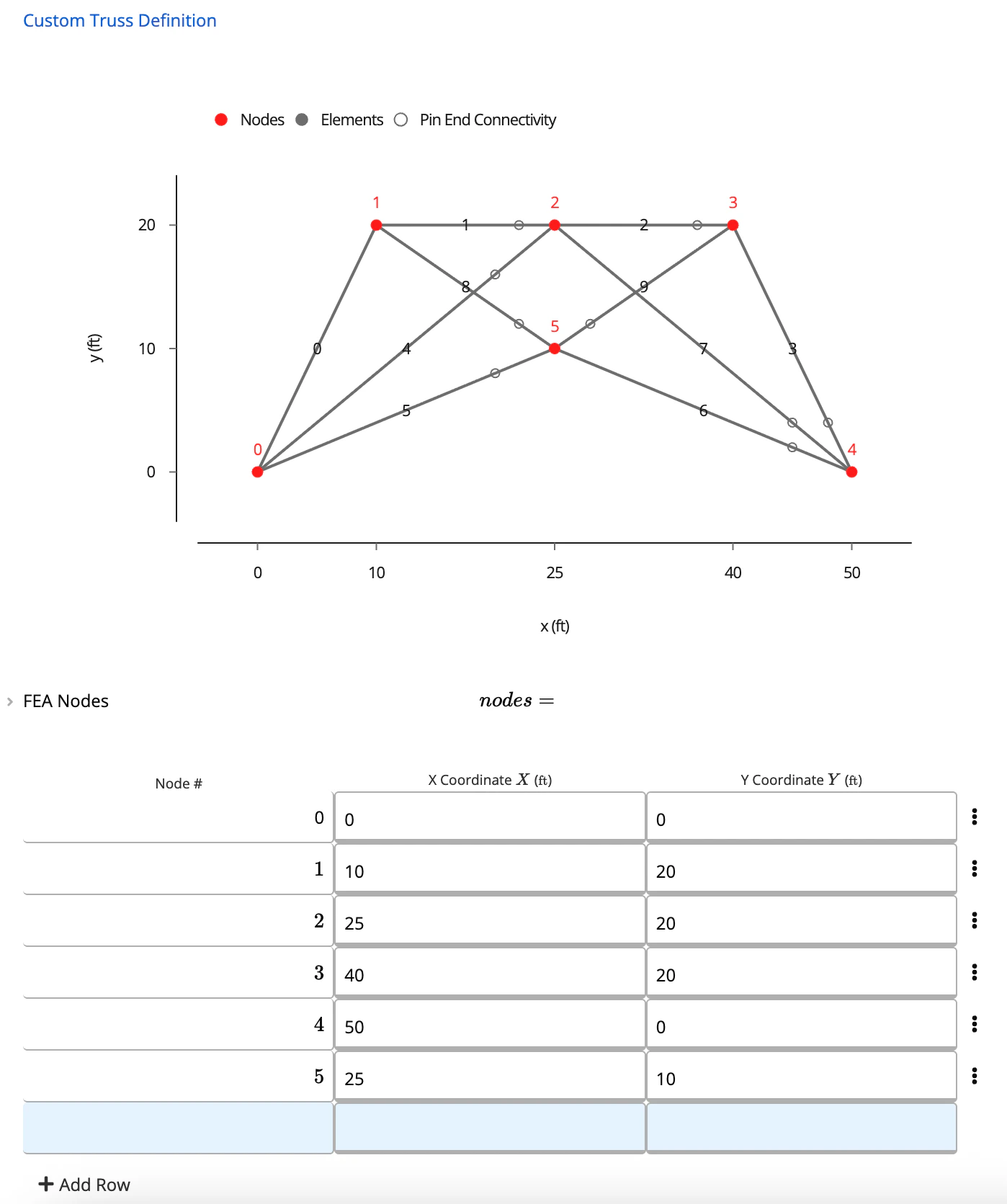 ***
Note: [Calcs.com](http://Calcs.com) currently does not auto detect members crossing other members or nodes. In the above example, if we have a member spanning from nodes 1 to 3, please input this as two members, from node 1 to 2 and 2 to 3
***
## Step 4 — Define the Elements
Next, connect the nodes to form the truss members.
Example from the video:
* Connect node **4 → 5**
* Connect node **2 → 5**
* Connect node **2 → 6**
* Connect node **5 → 6**
For each element, assign a **Member Type** (e.g., 1, 2, 3).These correspond to materials you'll assign later. It's important to note that your members should be
Member types typically represent different groups such as the top chord, bottom chord, and web members. Assign them clearly to make member selection easier later.
You can also set **fixity** here (e.g., pinned or fixed ends).
***
## Step 5 — Choose the Material Type for Your Members
Under **Member Selection**, you can choose:
* Hot Rolled Steel
* Cold-Formed Steel
* Timber
* **Custom Linked** (for custom shapes)
If you're using standard steel or timber, the **Member Selector** will display all available database shapes.
However, if your truss uses a **custom bar, pipe, or proprietary shape**, keep reading to learn how to model this.
***
## Step 6 — Create a Custom Cross-Section
Since no custom cross-sections exist yet, create one:
1. Add a new calculator.
2. Choose **Custom Cross-Section Property → Generic Cross-Section**.
3. Define your dimensions.
For example, if we had \*\*N12 bars \*\*for our web members, enter a circular section with **12 mm diameter**. Once saved, this custom section becomes available for linking.
***
Note: [Calcs.com](http://Calcs.com) currently does not auto detect members crossing other members or nodes. In the above example, if we have a member spanning from nodes 1 to 3, please input this as two members, from node 1 to 2 and 2 to 3
***
## Step 4 — Define the Elements
Next, connect the nodes to form the truss members.
Example from the video:
* Connect node **4 → 5**
* Connect node **2 → 5**
* Connect node **2 → 6**
* Connect node **5 → 6**
For each element, assign a **Member Type** (e.g., 1, 2, 3).These correspond to materials you'll assign later. It's important to note that your members should be
Member types typically represent different groups such as the top chord, bottom chord, and web members. Assign them clearly to make member selection easier later.
You can also set **fixity** here (e.g., pinned or fixed ends).
***
## Step 5 — Choose the Material Type for Your Members
Under **Member Selection**, you can choose:
* Hot Rolled Steel
* Cold-Formed Steel
* Timber
* **Custom Linked** (for custom shapes)
If you're using standard steel or timber, the **Member Selector** will display all available database shapes.
However, if your truss uses a **custom bar, pipe, or proprietary shape**, keep reading to learn how to model this.
***
## Step 6 — Create a Custom Cross-Section
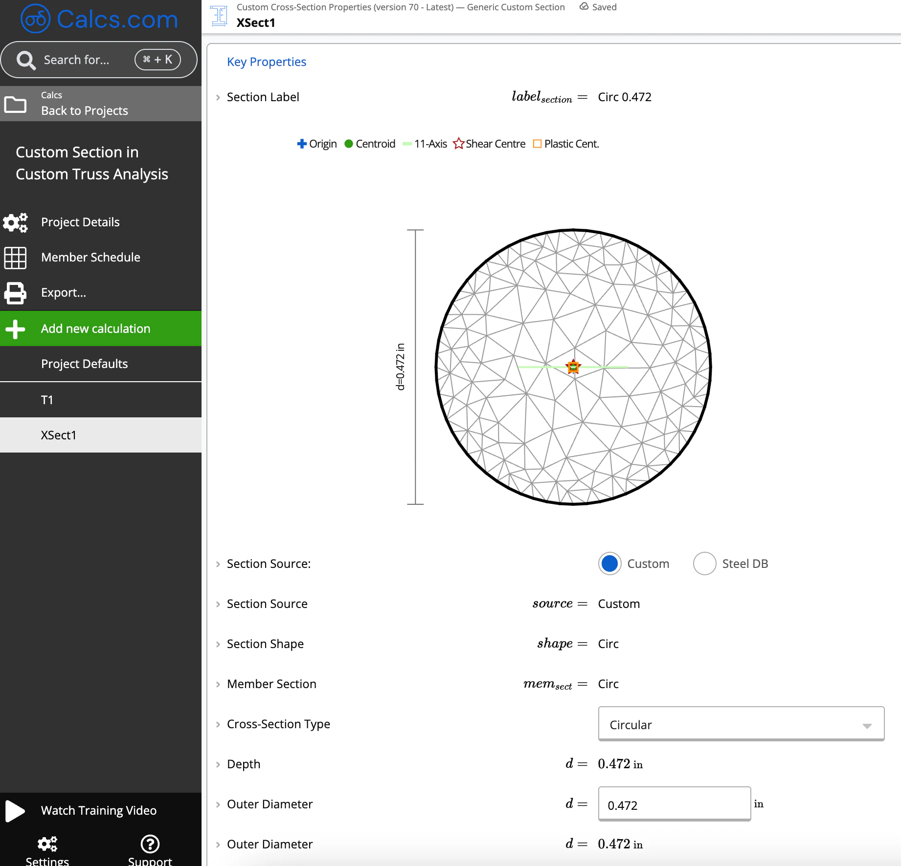
Since no custom cross-sections exist yet, create one:
1. Add a new calculator.
2. Choose **Custom Cross-Section Property → Generic Cross-Section**.
3. Define your dimensions.
For example, if we had \*\*N12 bars \*\*for our web members, enter a circular section with **12 mm diameter**. Once saved, this custom section becomes available for linking.
 ***
## Step 7 — Link the Custom Section to Truss Members
Return to your **Custom Truss Analysis**.
Under **Member Data**:
1. Find the **member type** you want to assign the custom section to (e.g., Member Type 1).
2. Change the section to your newly created **custom cross-section**.
The custom cross section calculator will now automatically calculate:
* Axial stiffness
* Bending stiffness
* Self-weight
Anywhere that **Member Type 1** appears in your truss geometry.
***
## Step 7 — Link the Custom Section to Truss Members
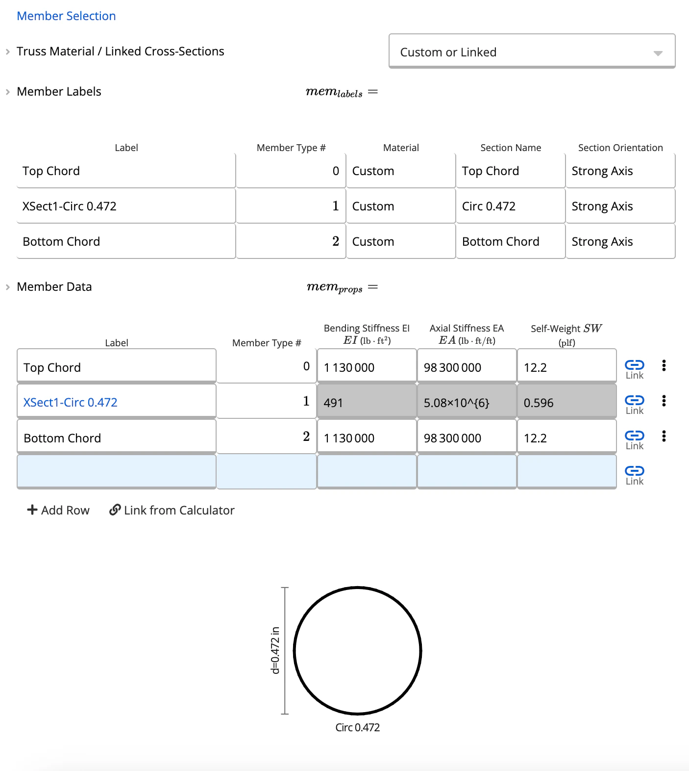
Return to your **Custom Truss Analysis**.
Under **Member Data**:
1. Find the **member type** you want to assign the custom section to (e.g., Member Type 1).
2. Change the section to your newly created **custom cross-section**.
The custom cross section calculator will now automatically calculate:
* Axial stiffness
* Bending stiffness
* Self-weight
Anywhere that **Member Type 1** appears in your truss geometry.
 ***
## Final Notes
* All **members** **assigned the same type** will now use your custom cross section.
* You can repeat this process for as many section types as needed.
* At any time, you can edit nodes, add new members, or adjust your custom section
Note that the truss analysis and custom cross section calculator do not currently design the strength of the section.
***
## Final Notes
* All **members** **assigned the same type** will now use your custom cross section.
* You can repeat this process for as many section types as needed.
* At any time, you can edit nodes, add new members, or adjust your custom section
Note that the truss analysis and custom cross section calculator do not currently design the strength of the section.