> ## Documentation Index
> Fetch the complete documentation index at: https://calcs.com/docs/llms.txt
> Use this file to discover all available pages before exploring further.
# Linking Design Calculators to Truss & Portal Frame Analysis
> How to use Design Only calculators to check capacity for members in Truss and Portal Frame analyses.
## Overview
In Calcs.com, the structural design process is often separated into two stages:
1. **Analysis:** Calculating forces (Demands) like displacements, moments, and shears based on geometry and stiffness. This is handled by the **Truss Analysis Wizard** or **Portal Frame Analysis**.
2. **Design:** Checking if a specific member size can withstand those forces (Capacity) using a **Design Only** calculator.
Check out the below video for a step-by-step walkthrough of the linking workflow using a Portal Frame example. **Note that the process for linking a Truss Analysis is nearly identical.**
Here are the specific steps for both workflows.
Currently, Calcs.com has Design Only modules available for the materials below.
**US Calculators:**
 **AU Calculators:**
 ***
## The Linking Workflow
Whether you are designing a steel warehouse frame or a timber roof truss, the workflow is identical.
Set up your geometry and loads in either the **Truss Analysis Wizard** or the **Portal Frame Analysis** calculator. This will generate your raw results: displacements, moments, and shears.
***
## The Linking Workflow
Whether you are designing a steel warehouse frame or a timber roof truss, the workflow is identical.
Set up your geometry and loads in either the **Truss Analysis Wizard** or the **Portal Frame Analysis** calculator. This will generate your raw results: displacements, moments, and shears.
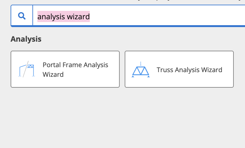 Click **Add New Calculation** and select a **Design Only** module appropriate for your material (e.g., *Timber Member (Design Only)*, *Steel Beam (Design Only)*, or *Cold Form Steel depending on the country*).
Find the **"Loads"** section in the Design calculator. Click the **Link** button (chain icon). Select your Analysis calculation as the source, and choose the specific member (e.g., "Top Chord" or "Left Leg").
Click **Add New Calculation** and select a **Design Only** module appropriate for your material (e.g., *Timber Member (Design Only)*, *Steel Beam (Design Only)*, or *Cold Form Steel depending on the country*).
Find the **"Loads"** section in the Design calculator. Click the **Link** button (chain icon). Select your Analysis calculation as the source, and choose the specific member (e.g., "Top Chord" or "Left Leg").
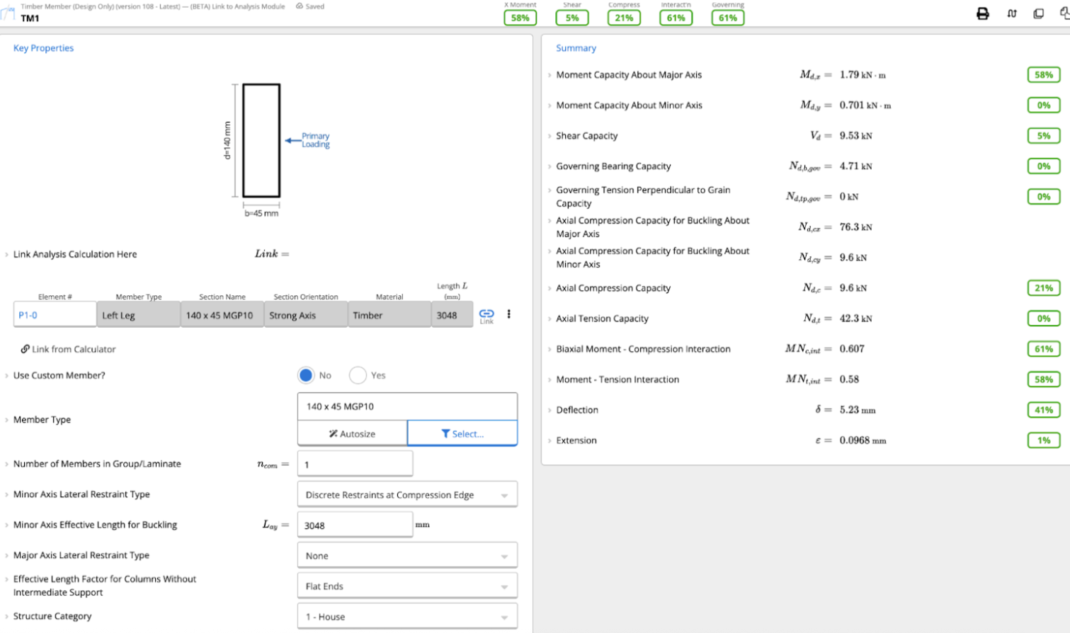
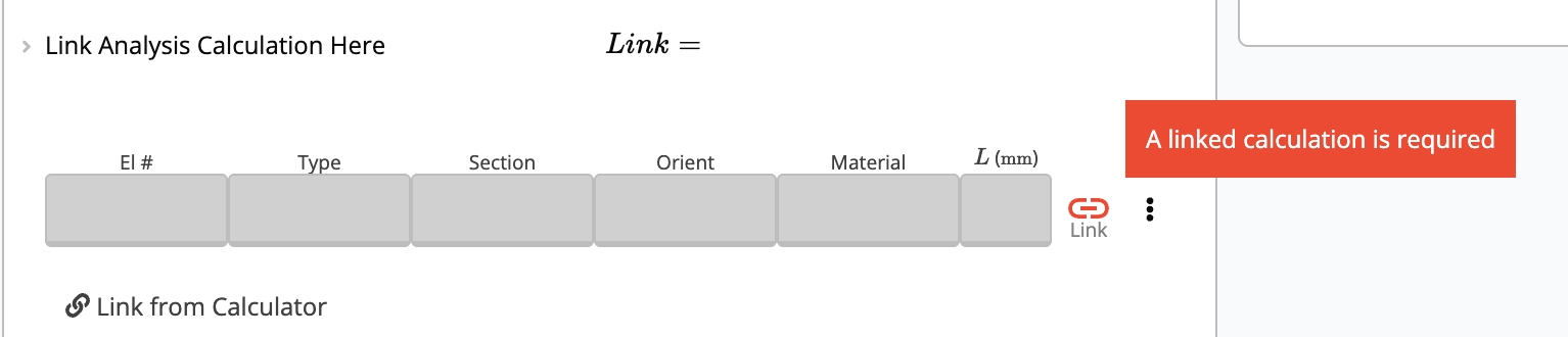 **Calculator after link:**
 ***
## Example A: Truss Analysis (Steel & Wood)
The **Truss Analysis Wizard** is strictly an FEA engine, it tells you *how much* force is in a member, but not if the member will break. Linking allows you to check code compliance.
**Instantly create a new Truss Analysis calculation:**
[**Create Truss Analysis Calculator**](https://calcs.com/new/sheet/trussAnalysis)
*(This link automatically opens a new project and sheet in Calcs.com.)*
### 1. Steel Truss Member
**Scenario:** Checking the Top Chord of a Flat Pratt Truss.
In the Truss Analysis Wizard, go to the **Truss Geometry** section:
* Set **Truss Type** to **"Flat Pratt Truss".**
***
## Example A: Truss Analysis (Steel & Wood)
The **Truss Analysis Wizard** is strictly an FEA engine, it tells you *how much* force is in a member, but not if the member will break. Linking allows you to check code compliance.
**Instantly create a new Truss Analysis calculation:**
[**Create Truss Analysis Calculator**](https://calcs.com/new/sheet/trussAnalysis)
*(This link automatically opens a new project and sheet in Calcs.com.)*
### 1. Steel Truss Member
**Scenario:** Checking the Top Chord of a Flat Pratt Truss.
In the Truss Analysis Wizard, go to the **Truss Geometry** section:
* Set **Truss Type** to **"Flat Pratt Truss".**
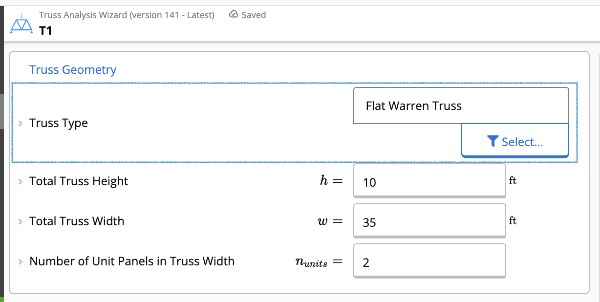 Scroll to the **Distributed Loads on Chords** section:
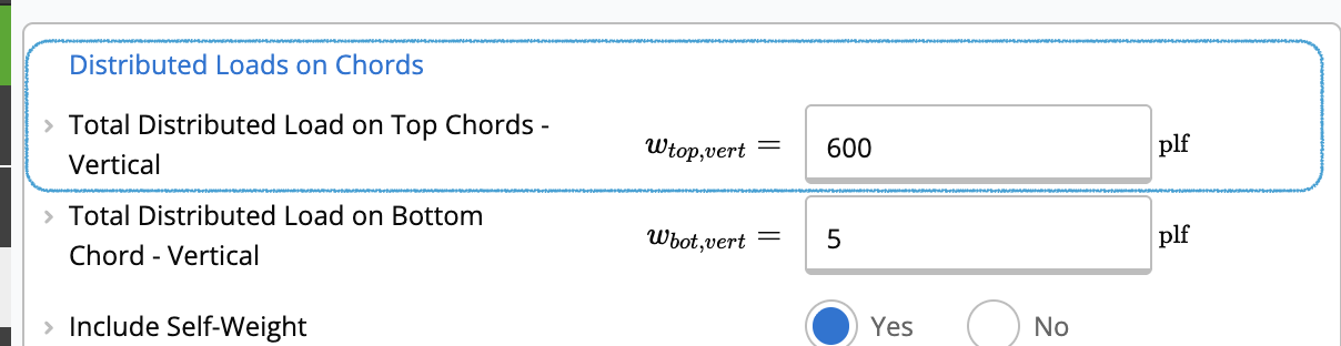
* Enter the load value in **Total Distributed Load on Top Chords - Vertical** (e.g., 600 plf for a downward gravity load).
Scroll to the **Distributed Loads on Chords** section:
* Enter the load value in **Total Distributed Load on Top Chords - Vertical** (e.g., 600 plf for a downward gravity load).
 Scroll down to the **Member Selection** section:
* Set **Truss Material** to **"Hot-Rolled Steel & RHS/SHS".**
* Go to **Top Chord Member** and select your preliminary section (e.g., **"HSS10X3X5/16"**).
Scroll down to the **Member Selection** section:
* Set **Truss Material** to **"Hot-Rolled Steel & RHS/SHS".**
* Go to **Top Chord Member** and select your preliminary section (e.g., **"HSS10X3X5/16"**).
 Go to the main menu and create a new **Steel Beam (Design Only)** calculator.
 In the new Design calculator, locate the **Loads** table. Click the **Link** button (chain icon), select your **Truss Analysis** calculation as the source, and choose **"Top Chord"**.
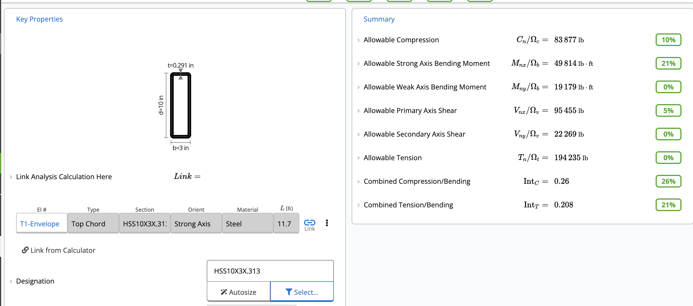
 The calculator automatically imports the worst-case **Axial Compression (C)**, **Axial Tension (T)**, **Strong Axis Moment (Mx)** and other properties.
Verify the **Summary** section to ensure the selected `HSS10X3X5/16` passes all code checks.
The calculator automatically imports the worst-case **Axial Compression (C)**, **Axial Tension (T)**, **Strong Axis Moment (Mx)** and other properties.
Verify the **Summary** section to ensure the selected `HSS10X3X5/16` passes all code checks.
 ### 2. Wood Truss Member
**Scenario:** Checking the Bottom Chord of a Residential Fink Truss.
In the Truss Analysis Wizard, go to the **Truss Geometry** section:
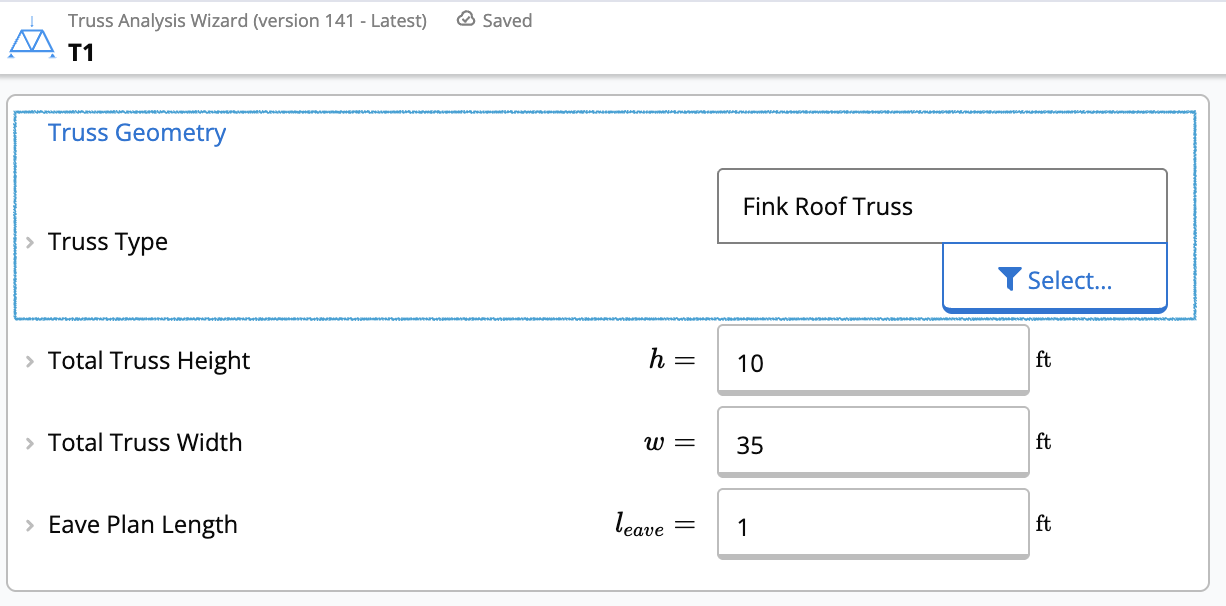
* Set **Truss Type** to **"Fink Roof Truss".**
### 2. Wood Truss Member
**Scenario:** Checking the Bottom Chord of a Residential Fink Truss.
In the Truss Analysis Wizard, go to the **Truss Geometry** section:
* Set **Truss Type** to **"Fink Roof Truss".**
 Scroll to the **Distributed Loads on Chords** section:
* Enter the load value in **Total Distributed Load on Bottom Chord - Vertical** (e.g., 50 plf for ceiling plasterboard and insulation).
Scroll to the **Distributed Loads on Chords** section:
* Enter the load value in **Total Distributed Load on Bottom Chord - Vertical** (e.g., 50 plf for ceiling plasterboard and insulation).
 Scroll down to the **Member Selection** section:
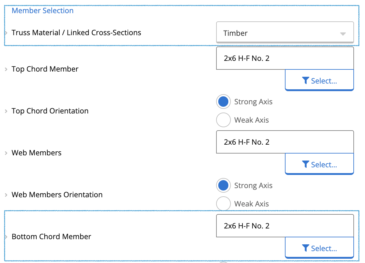
* Set **Truss Material** to **"Timber".**
* Go to **Bottom Chord Member** and select your preliminary section (e.g., **"2x6 No.2"**).
Scroll down to the **Member Selection** section:
* Set **Truss Material** to **"Timber".**
* Go to **Bottom Chord Member** and select your preliminary section (e.g., **"2x6 No.2"**).
 Go to the main menu and create a new **Wood Beam (Design Only)** calculator.
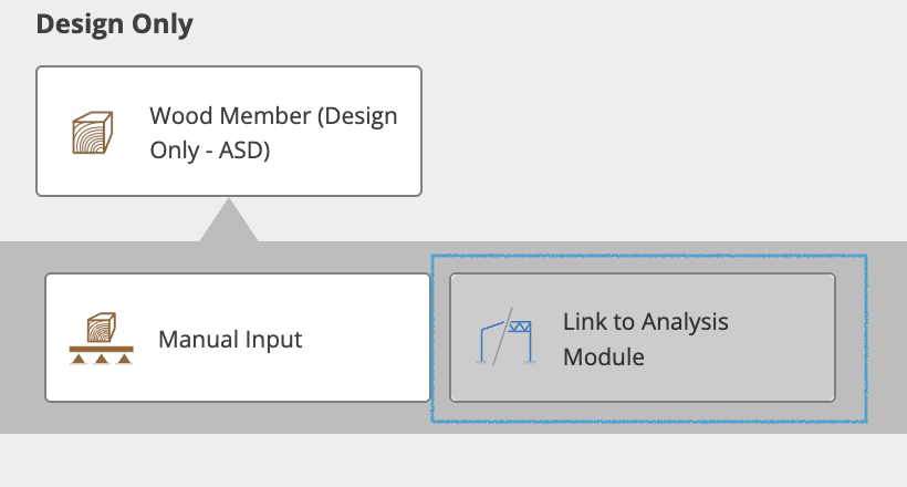 In the new Design calculator, locate the **Loads** table. Click the **Link** button (chain icon), select your **Truss Analysis** calculation as the source, and choose **"Bottom Chord"**.
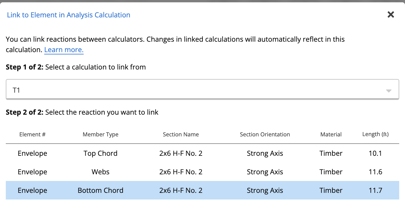 The calculator automatically imports the worst-case **Axial Tension (T)** and **Bending Moments (M)**.
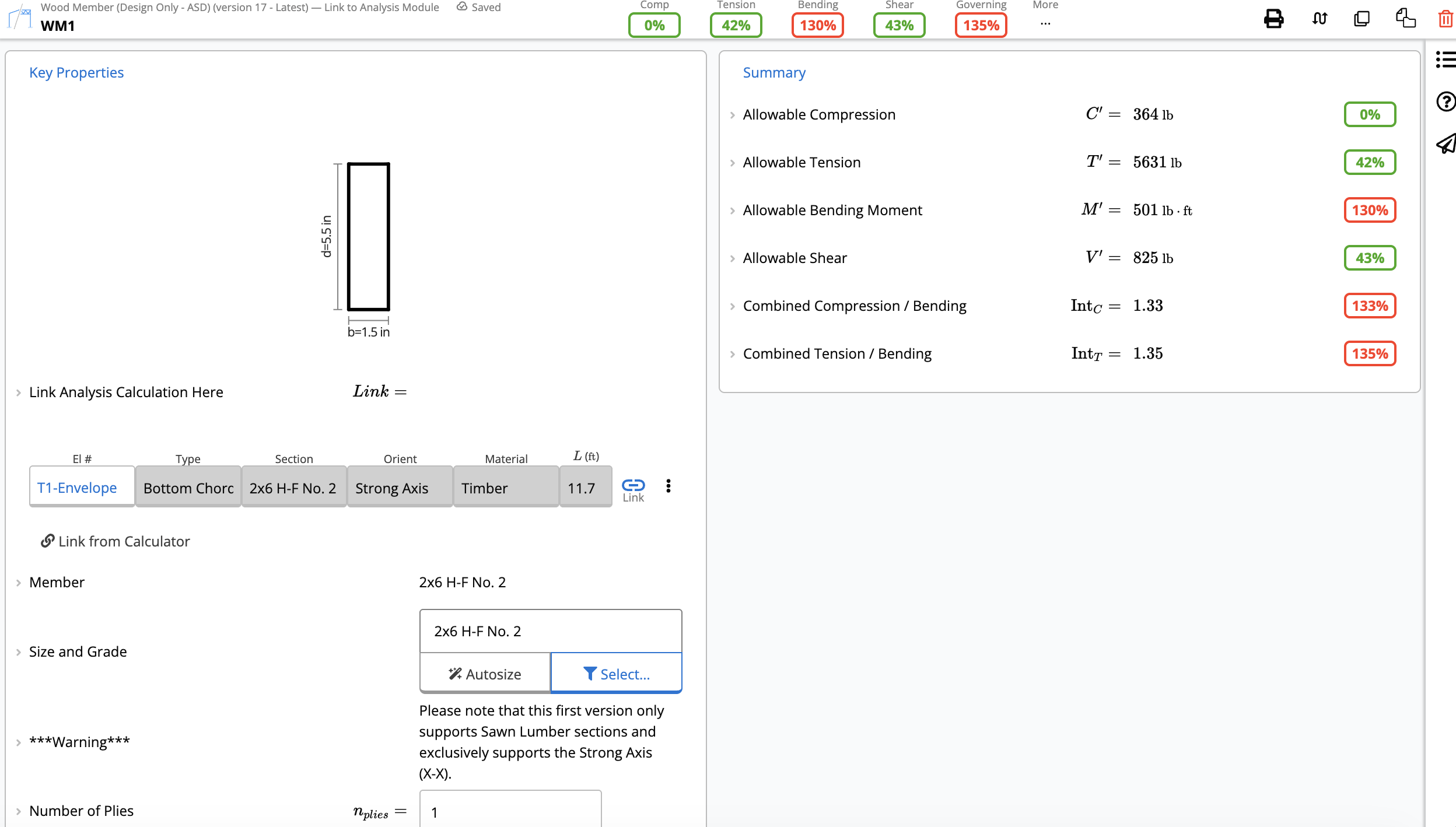
Verify the **Summary** section to ensure the selected timber grade passes the code checks (Utilization \< 100%). In this example, it is failing.
The calculator automatically imports the worst-case **Axial Tension (T)** and **Bending Moments (M)**.
Verify the **Summary** section to ensure the selected timber grade passes the code checks (Utilization \< 100%). In this example, it is failing.
 ***
## Example B: Portal Frame Analysis
This workflow is practically identical to the truss method explained above. The **Portal Frame Analysis Wizard** provides results for displacements, moments, and shears, but does not perform code checking on the members themselves.
**Instantly create a new Portal Frame Analysis calculation:**
[**Create Portal Frame Analysis Calculator**](https://calcs.com/new/sheet/portalFrameAnalysis)
*(This link automatically opens a new project and sheet in Calcs.com.)*
Configure your Portal Frame (e.g., a flat mono-slope frame). Run the analysis to generate the member forces.
Add a new **Design Only** calculation. For example, select **Timber Member (Design Only)**.
Connect the design sheet to the Portal Frame Analysis and select the specific member you want to check, such as the **Left Leg**.
The Design calculator will now verify the member against the building code, focusing on:
* **Moment Capacity**
* **Shear Capacity**
* **Compression Capacity**
* **Interaction Equations** (combined actions)
* **Deflection Criteria** (customizable in the design module)
***
## Example B: Portal Frame Analysis
This workflow is practically identical to the truss method explained above. The **Portal Frame Analysis Wizard** provides results for displacements, moments, and shears, but does not perform code checking on the members themselves.
**Instantly create a new Portal Frame Analysis calculation:**
[**Create Portal Frame Analysis Calculator**](https://calcs.com/new/sheet/portalFrameAnalysis)
*(This link automatically opens a new project and sheet in Calcs.com.)*
Configure your Portal Frame (e.g., a flat mono-slope frame). Run the analysis to generate the member forces.
Add a new **Design Only** calculation. For example, select **Timber Member (Design Only)**.
Connect the design sheet to the Portal Frame Analysis and select the specific member you want to check, such as the **Left Leg**.
The Design calculator will now verify the member against the building code, focusing on:
* **Moment Capacity**
* **Shear Capacity**
* **Compression Capacity**
* **Interaction Equations** (combined actions)
* **Deflection Criteria** (customizable in the design module)