> ## Documentation Index
> Fetch the complete documentation index at: https://calcs.com/docs/llms.txt
> Use this file to discover all available pages before exploring further.
# [USA Wood Beam] Hip Rafter
See how to design a Hip Rafter wood beam to ASD or LRFD requirements.
Learn how to translate your CAD plan and elevation directly to a Calcs.com calculation!
Download this example as a PDF: [Hip Rafter \[USA Timber Beam\]](https://s3.amazonaws.com/helpscout.net/docs/assets/5c09df402c7d3a31944ed720/attachments/6141d4382b380503dfdf14eb/Hip-Rafter-Article.pdf)
## This is what we have
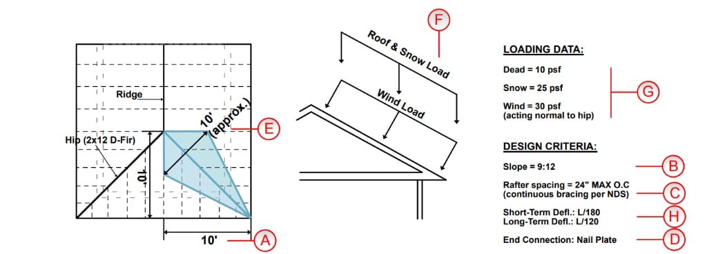
Start from the plan, elevation, and design criteria for the hip rafter. The lettered callouts (A–H) map to the inputs you'll enter in Calcs.com in the steps below.
 | Callout | Design information |
| ------- | -------------------------------------------------------------------------- |
| **A** | Side length = 10' |
| **B** | Roof slope = 9:12 |
| **C** | Rafter spacing = 24" max O.C. (continuous bracing per NDS) |
| **D** | End connection = nail plate |
| **E** | Hip length on plan ≈ 10' (tributary area \~ half the side width each side) |
| **F** | Gravity roof & snow loads (vertical) |
| **G** | Dead = 10 psf, Snow = 25 psf, Wind = 30 psf (normal to hip) |
| **H** | Short-term defl. L/180, long-term defl. L/120 |
## This is how we model it in Calcs.com
Open a **USA Wood Beam** calculation with the Hip Rafter preset, then work through Key Properties, Loads, and Design Conditions.
### Step 1 — Key Properties
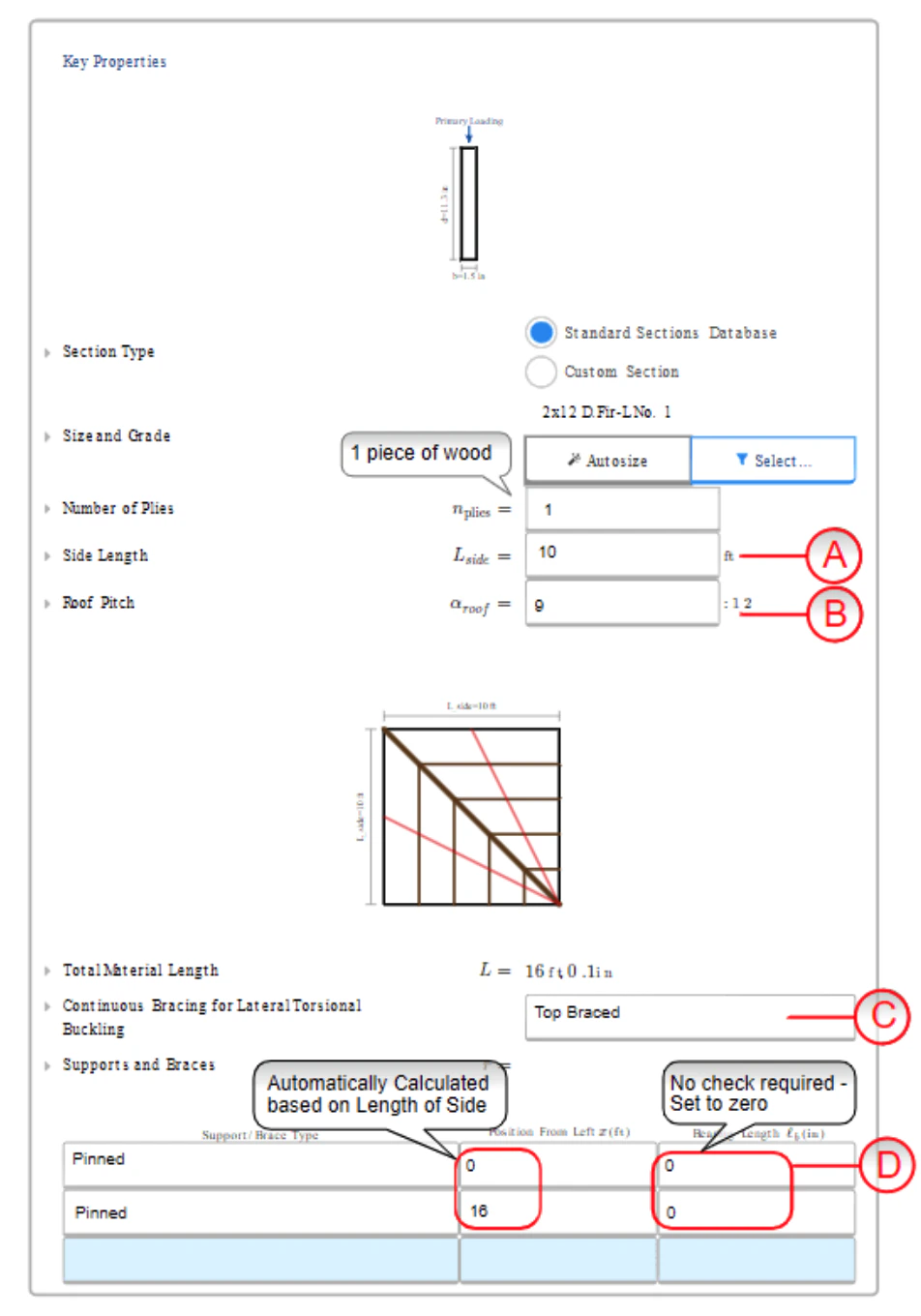
Enter the section, geometry, and bracing. Side length (**A**) and roof pitch (**B**) drive the calculated hip length and support positions. Continuous top bracing (**C**) matches the rafter spacing assumption. Set bearing length to zero when no bearing check is required (**D**).
| Callout | Design information |
| ------- | -------------------------------------------------------------------------- |
| **A** | Side length = 10' |
| **B** | Roof slope = 9:12 |
| **C** | Rafter spacing = 24" max O.C. (continuous bracing per NDS) |
| **D** | End connection = nail plate |
| **E** | Hip length on plan ≈ 10' (tributary area \~ half the side width each side) |
| **F** | Gravity roof & snow loads (vertical) |
| **G** | Dead = 10 psf, Snow = 25 psf, Wind = 30 psf (normal to hip) |
| **H** | Short-term defl. L/180, long-term defl. L/120 |
## This is how we model it in Calcs.com
Open a **USA Wood Beam** calculation with the Hip Rafter preset, then work through Key Properties, Loads, and Design Conditions.
### Step 1 — Key Properties
Enter the section, geometry, and bracing. Side length (**A**) and roof pitch (**B**) drive the calculated hip length and support positions. Continuous top bracing (**C**) matches the rafter spacing assumption. Set bearing length to zero when no bearing check is required (**D**).
 ### Step 2 — Loads
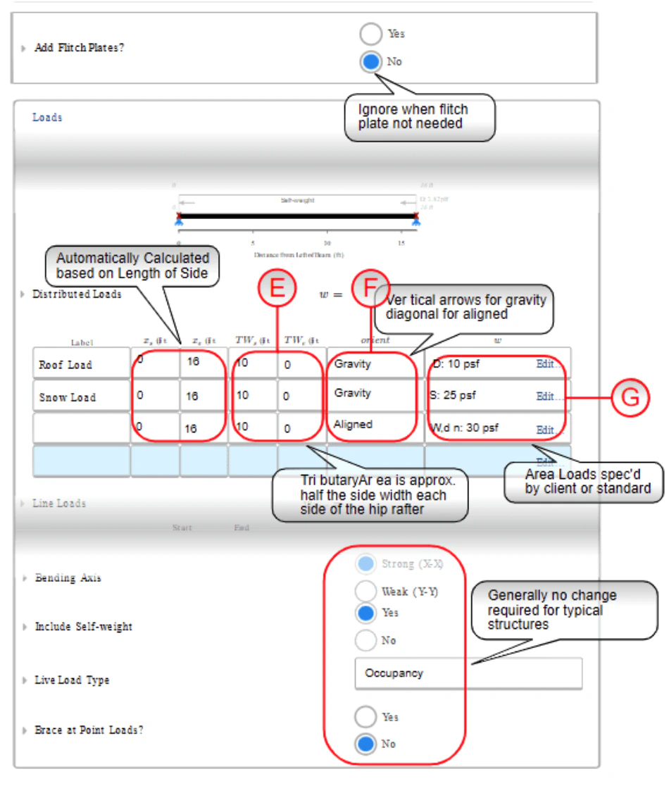
Apply the area loads from the design criteria (**G**) as distributed loads with a triangular tributary width (**E**): `TW_s` starts at the side length and tapers to zero at the ridge. Use **Gravity** orientation for roof/snow (**F**) and **Aligned** for wind acting normal to the hip.
### Step 2 — Loads
Apply the area loads from the design criteria (**G**) as distributed loads with a triangular tributary width (**E**): `TW_s` starts at the side length and tapers to zero at the ridge. Use **Gravity** orientation for roof/snow (**F**) and **Aligned** for wind acting normal to the hip.
 ### Step 3 — Design Conditions
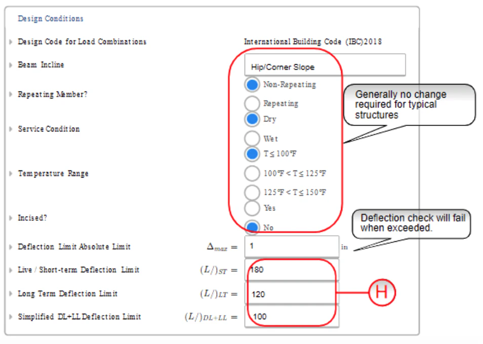
Set beam incline to **Hip/Corner Slope**, keep the typical wood service settings, and enter the deflection limits (**H**). The absolute deflection limit fails the check if exceeded.
### Step 3 — Design Conditions
Set beam incline to **Hip/Corner Slope**, keep the typical wood service settings, and enter the deflection limits (**H**). The absolute deflection limit fails the check if exceeded.