> ## Documentation Index
> Fetch the complete documentation index at: https://calcs.com/docs/llms.txt
> Use this file to discover all available pages before exploring further.
# Masonry Shear Wall (LRFD)
> Analyze reinforced CMU shear walls for in-plane axial load, moment, and shear under TMS 402/602-22 LRFD provisions, including walls with openings.
**Instantly create a new Masonry Shear Wall (LRFD) calculation by clicking here:**
[**Create Masonry Shear Wall (LRFD) Calculator**](https://calcs.com/new/sheet/masonryShearWallLRFD)
*(This link automatically opens a new project and sheet in Calcs.com.)*
This calculator checks reinforced masonry shear walls for in-plane axial load, overturning moment, and shear using factored load combinations per TMS 402/602-22. It supports Ordinary, Intermediate, and Special reinforced shear wall designations, walls with or without openings, and plots a moment-axial interaction diagram for each case.
This calculator follows **TMS 402/602-22 Chapter 9** (LRFD). Walls with openings use the **segmented pier method** per Section 4.1.6.
## Choosing the right calculator
Calcs.com has three TMS 402/602-22 masonry wall calculators. They are not interchangeable.
Out-of-plane loading on a load-bearing wall span, checked per linear foot using LRFD.
Same out-of-plane problem using allowable stress design (TMS Chapter 8).
**This page.** In-plane lateral force-resisting walls with multi-story geometry and optional openings.
This calculator is for **in-plane** lateral force-resisting walls only. For out-of-plane wind or seismic pressure on a load-bearing wall span, use one of the gravity wall calculators instead.
## When to use this calculator
Use this calculator when a CMU wall acts as a lateral force-resisting element and must carry in-plane shear and overturning from wind or seismic loads.
**Not a gravity wall calculator.** Out-of-plane loading on load-bearing wall spans is not covered here. Use [Masonry Gravity Wall (LRFD)](/calculations/us/masonry-gravity-wall-lrfd) or [Masonry Gravity Wall (ASD)](/calculations/us/masonry-gravity-wall-asd), depending on your design method.
**Boundary elements are not modeled.** Capacity is based on uniformly distributed vertical steel. Concentrated boundary reinforcement is outside this sheet.
## Assumptions and limitations
* Strain compatibility is assumed between reinforcement, grout, and masonry.
* Vertical reinforcement is uniformly distributed along the wall length.
* Walls with openings use the segmented pier method per TMS 402/602-22 Section 4.1.6. Openings must be vertically aligned across stories.
* Spandrel stiffness above and below openings is not included in pier stiffness.
* Non-aligned or overlapping openings are not supported.
* Only one layer of reinforcing steel is supported.
Full assumptions and limitations are listed in the Sheet Details tab within the calculator.
**How to read the sheet:** enter **inputs** first, review **calculations** in Detailed view, then read pass/fail in the **Summary** on the right. The **Shear Wall Diagram** and **Interaction Diagram** at the top update as inputs change.
## Inputs
Work through the input sections in order. Geometry, reinforcement, and story loads feed all downstream checks.
These inputs feed section properties, self-weight, the **Shear Wall Diagram**, and opening layout.
* **Story Height** and **Number of Stories**: define the wall height used in slenderness, shear, and story-level load tables.
* **Total Wall Length**: plan length of the shear wall system.
* **Masonry Type**, **Concrete Masonry Unit Size**, **CMU Pattern**, and **Mortar Type**: feed unit dimensions and material properties from CMU-TEC references.
* **Fully or Partially Grouted?**, **Specified Compressive Strength**, **Masonry Modulus of Elasticity**, and density inputs: feed **Geometric Properties of CMU Wall** and strength checks.
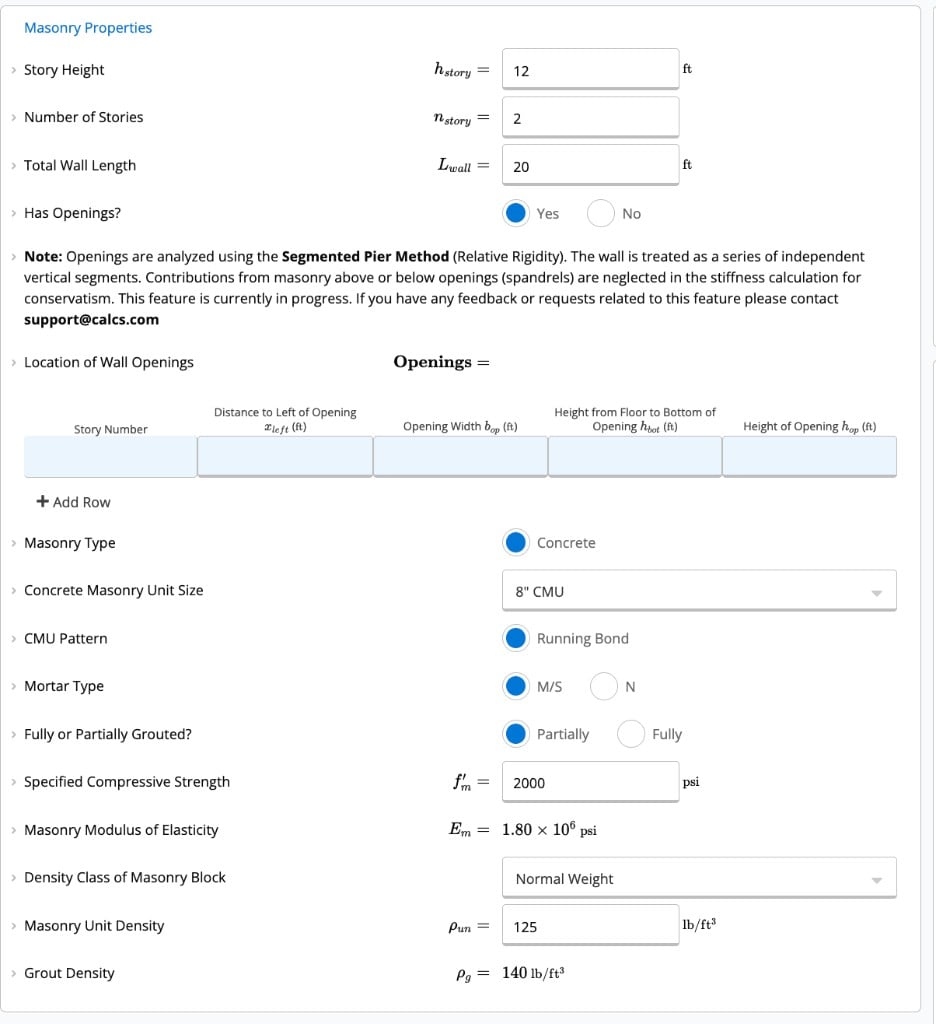 Set **Has Openings?** to **Yes** when the wall has doors, windows, or other penetrations; **No** for a solid wall over the full length and height. When openings are present, the calculator treats the wall as a series of solid masonry **piers** and distributes in-plane base shear to each pier by relative stiffness (the **Segmented Pier Method** per TMS 402/602-22 Section 4.1.6).
Contributions from masonry above or below openings (spandrels) are neglected in the stiffness calculation for conservatism. Non-aligned openings across stories are not supported because they require load transfer analysis (such as strut-and-tie) outside this pier-based model.
Use **Location of Wall Openings** to define each opening:
* **Story Number**: set to **All** when the same opening layout repeats on every story, or enter an individual story number for story-specific openings.
* **Distance to Left of Opening**: horizontal distance from the left end of the wall to the left edge of the opening.
* **Opening Width** and **Height of Opening**: plan and vertical dimensions of the opening.
* **Height from Floor to Bottom of Opening**: sill height measured from the story floor.
Openings must stay within the wall length and height, must not overlap or touch each other, and must align vertically across stories (same horizontal position and width at each level). Merge adjacent or edge-touching openings into one larger opening before entering them. The **Shear Wall Diagram** updates as you enter opening geometry.
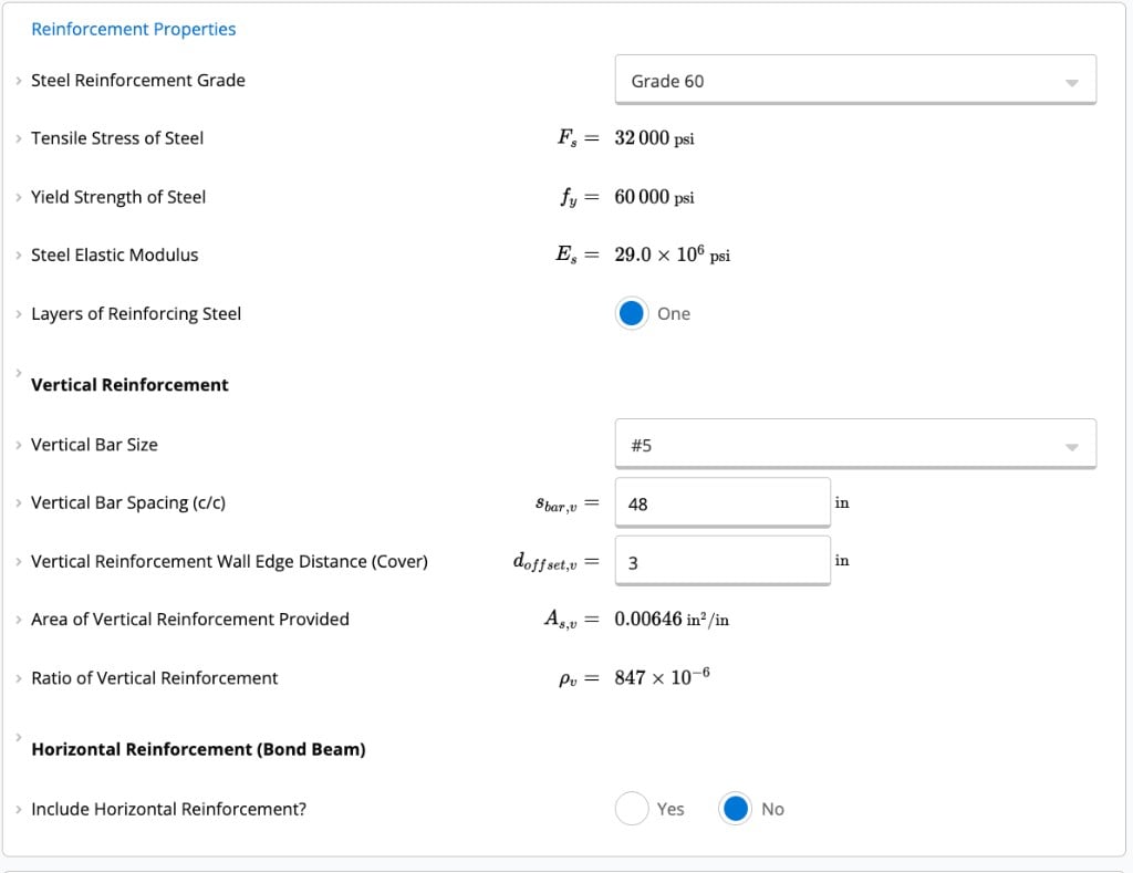
* **Steel Reinforcement Grade**, **Vertical Bar Size**, and **Vertical Bar Spacing (c/c)**: feed axial, flexural, and shear capacity. The calculator validates spacing against TMS 402/602-22 limits for the selected **Shear Wall Designation**.
* **Vertical Reinforcement Wall Edge Distance (Cover)**: horizontal distance from the wall end to the nearest vertical bar.
* **Vertical Reinforcement Opening Edge Distance (Cover)**: appears when openings are present. Horizontal distance from an opening edge to the nearest vertical bar.
* **Include Horizontal Reinforcement?**, **Horizontal Bar Size**, and **Horizontal Bar Spacing (c/c)**: optional bond-beam steel checked in **Horizontal Reinforcement (Bond Beam)**.
Set **Has Openings?** to **Yes** when the wall has doors, windows, or other penetrations; **No** for a solid wall over the full length and height. When openings are present, the calculator treats the wall as a series of solid masonry **piers** and distributes in-plane base shear to each pier by relative stiffness (the **Segmented Pier Method** per TMS 402/602-22 Section 4.1.6).
Contributions from masonry above or below openings (spandrels) are neglected in the stiffness calculation for conservatism. Non-aligned openings across stories are not supported because they require load transfer analysis (such as strut-and-tie) outside this pier-based model.
Use **Location of Wall Openings** to define each opening:
* **Story Number**: set to **All** when the same opening layout repeats on every story, or enter an individual story number for story-specific openings.
* **Distance to Left of Opening**: horizontal distance from the left end of the wall to the left edge of the opening.
* **Opening Width** and **Height of Opening**: plan and vertical dimensions of the opening.
* **Height from Floor to Bottom of Opening**: sill height measured from the story floor.
Openings must stay within the wall length and height, must not overlap or touch each other, and must align vertically across stories (same horizontal position and width at each level). Merge adjacent or edge-touching openings into one larger opening before entering them. The **Shear Wall Diagram** updates as you enter opening geometry.
* **Steel Reinforcement Grade**, **Vertical Bar Size**, and **Vertical Bar Spacing (c/c)**: feed axial, flexural, and shear capacity. The calculator validates spacing against TMS 402/602-22 limits for the selected **Shear Wall Designation**.
* **Vertical Reinforcement Wall Edge Distance (Cover)**: horizontal distance from the wall end to the nearest vertical bar.
* **Vertical Reinforcement Opening Edge Distance (Cover)**: appears when openings are present. Horizontal distance from an opening edge to the nearest vertical bar.
* **Include Horizontal Reinforcement?**, **Horizontal Bar Size**, and **Horizontal Bar Spacing (c/c)**: optional bond-beam steel checked in **Horizontal Reinforcement (Bond Beam)**.
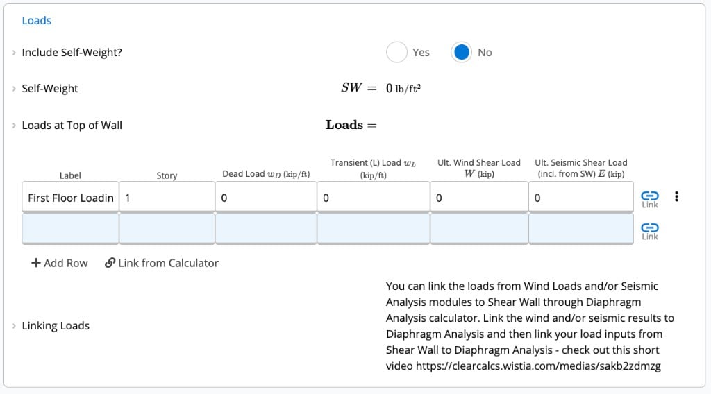
 Enter unfactored loads per story. The calculator applies LRFD load factors in **Load Combination Analysis**.
* **Include Self-Weight?**: toggles whether **Self-Weight** is added as a dead load.
* **Loads at Top of Wall**: enter axial, shear, and moment loads by story. Loads can be linked from other Calcs.com sheets such as wind or seismic analysis modules.
* **Seismic Design Category**: appears when seismic loads are entered. Filters available **Shear Wall Designation** options per TMS 402/602-22 Section 7.3.2.
* **Shear Wall Designation**: set to Ordinary, Intermediate, or Special based on SDC. The calculator applies the corresponding reinforcement and detailing limits.
Use **Link from Calculator** to pull wind or seismic reactions from a [Diaphragm Analysis](/calculations/us/how_to_use_the_diaphragm_analysis_calculator) sheet. See the load-linking walkthrough in [Load Linking: Wind Loads → Diaphragm → Shear Wall](/learn_calcs/getting_started/onboarding_videos/load-linking-wind-diaphragm-shear-wall).
Enter unfactored loads per story. The calculator applies LRFD load factors in **Load Combination Analysis**.
* **Include Self-Weight?**: toggles whether **Self-Weight** is added as a dead load.
* **Loads at Top of Wall**: enter axial, shear, and moment loads by story. Loads can be linked from other Calcs.com sheets such as wind or seismic analysis modules.
* **Seismic Design Category**: appears when seismic loads are entered. Filters available **Shear Wall Designation** options per TMS 402/602-22 Section 7.3.2.
* **Shear Wall Designation**: set to Ordinary, Intermediate, or Special based on SDC. The calculator applies the corresponding reinforcement and detailing limits.
Use **Link from Calculator** to pull wind or seismic reactions from a [Diaphragm Analysis](/calculations/us/how_to_use_the_diaphragm_analysis_calculator) sheet. See the load-linking walkthrough in [Load Linking: Wind Loads → Diaphragm → Shear Wall](/learn_calcs/getting_started/onboarding_videos/load-linking-wind-diaphragm-shear-wall).
 ## Calculations
After inputs are set, the calculator builds section properties, applies LRFD load combinations, and checks axial, flexural, and shear capacity. Open Detailed view to see intermediate steps and TMS 402/602-22 clause references for each section below.
### Geometric Properties of CMU Wall
**Geometric Properties of CMU Wall** computes net area, moment of inertia, section modulus, and self-weight from the masonry and reinforcement inputs above.
### Design Conditions
**Design Conditions** pulls the load combination code from project defaults (IBC 2024 / TMS 402/602-22) and confirms the design standard edition in use.
### Load Combination Analysis
**Load Combination Analysis** expands LRFD strength combinations and reports factored axial, moment, and shear demands at the governing story and load case.
### Wall Properties
**Wall Properties** reports slenderness, effective shear depth, and story-level demand summaries used in the strength checks below.
### Openings in Wall
When **Has Openings?** is Yes, **Openings in Wall** validates opening geometry and builds the expanded opening tables used in the segmented analysis. Checks include:
* Openings must fall within the wall height and length.
* Openings must not overlap or touch; merge adjacent openings into one entry.
* Multi-story walls require vertical alignment of opening position and width across stories.
**Locations of All Wall Openings**, **Locations of All Repeated Wall Openings**, and **Locations of Individual Wall Openings** list the resolved opening layout per story after the input table is processed.
### Segmented Method Analysis (Piers)
For walls with openings, **Segmented Method Analysis (Piers)** divides the wall into solid piers, calculates pier length and aspect ratio, and distributes story base shear among piers by relative rigidity per TMS 402/602-22 Section 4.1.6.
* **Pier Boundary Condition**: **Cantilever** (fixed base, free top) or **Fixed-Fixed** (top rotation restrained). This feeds pier stiffness in the segmented analysis.
* **Modulus of Rigidity**: shear modulus used in pier stiffness, taken as 0.4 × masonry modulus of elasticity per TMS 402 Section 4.2.2.2.
* **Pier Tributary Width and Axial Load**: tributary area and axial load assigned to each pier segment.
Pier-level strength checks appear in **Piers Design Demands (Factored Forces)** and **Piers Capacities**. Select a **Story** and **Pier** at the top of the sheet to review demands and the pier-specific **Interaction Diagram**.
### In-Plane Shear (TMS 402/602-22, Section 9.3.3.1.2)
**In-Plane Shear** checks factored in-plane shear demand against masonry shear capacity. For solid walls (**Has Openings?** = No), summary rows **In-Plane Shear Demand** and **In-Plane Shear Capacity** report the governing result. For walls with openings, pier-level shear checks appear in **Piers Capacities**.
### Moment-Axial Interaction (TMS 402-22, Section 9)
Combined in-plane axial and bending capacity is evaluated in **Interaction Diagram (Axial & Flexure)**. The **Interaction Utilization Check** table reports utilization for every load combination.
**Maximum Area of Flexural Tensile Reinforcement (TMS 402/602-22, Section 9.3.5.6.1.)** checks ductility limits on vertical steel for the selected **Shear Wall Designation**.
* Geometric Properties of CMU Wall
* Load Combination Analysis
* Wall Properties
* Openings in Wall
* Segmented Method Analysis (Piers)
* Piers Design Demands (Factored Forces)
* Piers Capacities
* In-Plane Shear (TMS 402/602-22, Section 9.3.3.1.2.)
* Interaction Diagram (Axial & Flexure)
* Maximum Area of Flexural Tensile Reinforcement (TMS 402/602-22, Section 9.3.5.6.1.)
## Results
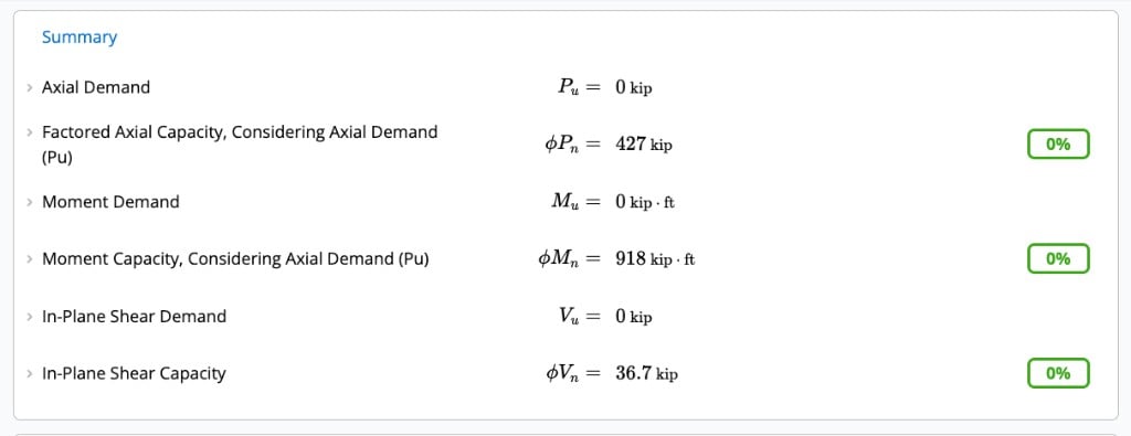
The **Summary** panel on the right collects governing pass/fail outcomes.
**Axial Demand** vs **Factored Axial Capacity, Considering Axial Demand (Pu)**
**Moment Demand** vs **Moment Capacity, Considering Axial Demand (Pu)**
**In-Plane Shear Demand** vs **In-Plane Shear Capacity**
**Interaction Governing Utilization** across load combinations
Green badges indicate passing utilization; red badges flag a governing failure.
### Solid walls (no openings)
When **Has Openings?** is No, the Summary reports wall-level demands and capacities for the full wall section:
* **Axial Demand** vs **Factored Axial Capacity, Considering Axial Demand (Pu)**
* **Moment Demand** vs **Moment Capacity, Considering Axial Demand (Pu)**
* **In-Plane Shear Demand** vs **In-Plane Shear Capacity**
## Calculations
After inputs are set, the calculator builds section properties, applies LRFD load combinations, and checks axial, flexural, and shear capacity. Open Detailed view to see intermediate steps and TMS 402/602-22 clause references for each section below.
### Geometric Properties of CMU Wall
**Geometric Properties of CMU Wall** computes net area, moment of inertia, section modulus, and self-weight from the masonry and reinforcement inputs above.
### Design Conditions
**Design Conditions** pulls the load combination code from project defaults (IBC 2024 / TMS 402/602-22) and confirms the design standard edition in use.
### Load Combination Analysis
**Load Combination Analysis** expands LRFD strength combinations and reports factored axial, moment, and shear demands at the governing story and load case.
### Wall Properties
**Wall Properties** reports slenderness, effective shear depth, and story-level demand summaries used in the strength checks below.
### Openings in Wall
When **Has Openings?** is Yes, **Openings in Wall** validates opening geometry and builds the expanded opening tables used in the segmented analysis. Checks include:
* Openings must fall within the wall height and length.
* Openings must not overlap or touch; merge adjacent openings into one entry.
* Multi-story walls require vertical alignment of opening position and width across stories.
**Locations of All Wall Openings**, **Locations of All Repeated Wall Openings**, and **Locations of Individual Wall Openings** list the resolved opening layout per story after the input table is processed.
### Segmented Method Analysis (Piers)
For walls with openings, **Segmented Method Analysis (Piers)** divides the wall into solid piers, calculates pier length and aspect ratio, and distributes story base shear among piers by relative rigidity per TMS 402/602-22 Section 4.1.6.
* **Pier Boundary Condition**: **Cantilever** (fixed base, free top) or **Fixed-Fixed** (top rotation restrained). This feeds pier stiffness in the segmented analysis.
* **Modulus of Rigidity**: shear modulus used in pier stiffness, taken as 0.4 × masonry modulus of elasticity per TMS 402 Section 4.2.2.2.
* **Pier Tributary Width and Axial Load**: tributary area and axial load assigned to each pier segment.
Pier-level strength checks appear in **Piers Design Demands (Factored Forces)** and **Piers Capacities**. Select a **Story** and **Pier** at the top of the sheet to review demands and the pier-specific **Interaction Diagram**.
### In-Plane Shear (TMS 402/602-22, Section 9.3.3.1.2)
**In-Plane Shear** checks factored in-plane shear demand against masonry shear capacity. For solid walls (**Has Openings?** = No), summary rows **In-Plane Shear Demand** and **In-Plane Shear Capacity** report the governing result. For walls with openings, pier-level shear checks appear in **Piers Capacities**.
### Moment-Axial Interaction (TMS 402-22, Section 9)
Combined in-plane axial and bending capacity is evaluated in **Interaction Diagram (Axial & Flexure)**. The **Interaction Utilization Check** table reports utilization for every load combination.
**Maximum Area of Flexural Tensile Reinforcement (TMS 402/602-22, Section 9.3.5.6.1.)** checks ductility limits on vertical steel for the selected **Shear Wall Designation**.
* Geometric Properties of CMU Wall
* Load Combination Analysis
* Wall Properties
* Openings in Wall
* Segmented Method Analysis (Piers)
* Piers Design Demands (Factored Forces)
* Piers Capacities
* In-Plane Shear (TMS 402/602-22, Section 9.3.3.1.2.)
* Interaction Diagram (Axial & Flexure)
* Maximum Area of Flexural Tensile Reinforcement (TMS 402/602-22, Section 9.3.5.6.1.)
## Results
The **Summary** panel on the right collects governing pass/fail outcomes.
**Axial Demand** vs **Factored Axial Capacity, Considering Axial Demand (Pu)**
**Moment Demand** vs **Moment Capacity, Considering Axial Demand (Pu)**
**In-Plane Shear Demand** vs **In-Plane Shear Capacity**
**Interaction Governing Utilization** across load combinations
Green badges indicate passing utilization; red badges flag a governing failure.
### Solid walls (no openings)
When **Has Openings?** is No, the Summary reports wall-level demands and capacities for the full wall section:
* **Axial Demand** vs **Factored Axial Capacity, Considering Axial Demand (Pu)**
* **Moment Demand** vs **Moment Capacity, Considering Axial Demand (Pu)**
* **In-Plane Shear Demand** vs **In-Plane Shear Capacity**
 ### Walls with openings
When **Has Openings?** is Yes, governing checks move to the pier level:
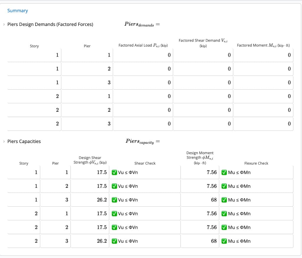
* **Piers Design Demands (Factored Forces)**: factored axial, shear, and moment for every pier on every story.
* **Piers Capacities**: design shear and moment strength plus pass/fail checks (✅ Vu ≤ ΦVn and ✅ Mu ≤ ΦMn) for each pier.
* **Story** and **Pier** selectors at the top of the sheet filter the **Interaction Diagram** and summary demands for one pier at a time.
* Warnings appear in Summary when one or more piers fail shear or flexure design checks.
### Walls with openings
When **Has Openings?** is Yes, governing checks move to the pier level:
* **Piers Design Demands (Factored Forces)**: factored axial, shear, and moment for every pier on every story.
* **Piers Capacities**: design shear and moment strength plus pass/fail checks (✅ Vu ≤ ΦVn and ✅ Mu ≤ ΦMn) for each pier.
* **Story** and **Pier** selectors at the top of the sheet filter the **Interaction Diagram** and summary demands for one pier at a time.
* Warnings appear in Summary when one or more piers fail shear or flexure design checks.
 Open **Segmented Method Analysis (Piers)** in Detailed view for pier geometry, stiffness distribution, and tributary assignments.
Switch to **Detailed** using the toggle at the top of the calculator to see every intermediate step and the relevant TMS 402-22 clause for each check.
### Reading the diagrams
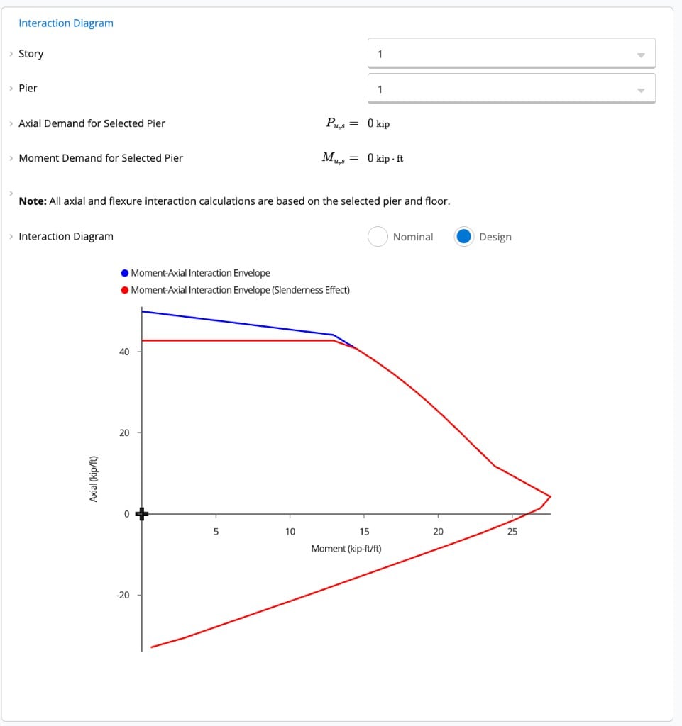
The **Interaction Diagram** plots the moment-axial capacity envelope. Each LRFD load combination appears as a point. Points inside the envelope correspond to passing rows in **Interaction Utilization Check**. For walls with openings, use the **Story** and **Pier** selectors to view the diagram for an individual pier segment.
Toggle **Interaction Diagram** between **Design** (factored ΦPn and ΦMn) and **Nominal** (unfactored Pn and Mn) capacity when reviewing pier or wall results.
Open **Segmented Method Analysis (Piers)** in Detailed view for pier geometry, stiffness distribution, and tributary assignments.
Switch to **Detailed** using the toggle at the top of the calculator to see every intermediate step and the relevant TMS 402-22 clause for each check.
### Reading the diagrams
The **Interaction Diagram** plots the moment-axial capacity envelope. Each LRFD load combination appears as a point. Points inside the envelope correspond to passing rows in **Interaction Utilization Check**. For walls with openings, use the **Story** and **Pier** selectors to view the diagram for an individual pier segment.
Toggle **Interaction Diagram** between **Design** (factored ΦPn and ΦMn) and **Nominal** (unfactored Pn and Mn) capacity when reviewing pier or wall results.
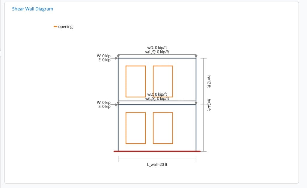
 The **Shear Wall Diagram** shows story heights, opening locations, and pier layout based on **Masonry Properties** and **Location of Wall Openings** inputs. Update the diagram by changing opening geometry or story count.
 ## Troubleshooting
Check the validation message next to the field. Common causes include invalid opening geometry, bar spacings outside TMS limits for the selected **Shear Wall Designation**, or story load entries that conflict with **Number of Stories**.
For openings, also check that openings stay inside the wall bounds, do not overlap, and align vertically across stories. Merge edge-touching or adjacent openings into a single wider opening.
CMU openings must share the same **Distance to Left of Opening** and **Opening Width** at every story where they occur. Use **Story Number** = **All** when the same layout repeats on every floor, or verify that story-specific rows match horizontally.
Open **Piers Capacities** in Detailed view to find the governing pier and story. Increase pier width by reducing opening size, add reinforcement, or review **Pier Boundary Condition** and **Vertical Reinforcement Opening Edge Distance (Cover)**.
**Seismic Design Category** filters available designations per TMS 402/602-22 Section 7.3.2. Open **Design Conditions** and the Loads section to confirm SDC and entered seismic loads.
Open that check in Detailed view to see which inputs feed the calculation. Summary rows link to the governing section. Use the input list above to find the corresponding fields in the sheet.
## Related calculators
Out-of-plane loading on load-bearing CMU walls (LRFD).
Out-of-plane loading on load-bearing CMU walls (ASD).
Worked example for reinforced masonry wall design context.
## Troubleshooting
Check the validation message next to the field. Common causes include invalid opening geometry, bar spacings outside TMS limits for the selected **Shear Wall Designation**, or story load entries that conflict with **Number of Stories**.
For openings, also check that openings stay inside the wall bounds, do not overlap, and align vertically across stories. Merge edge-touching or adjacent openings into a single wider opening.
CMU openings must share the same **Distance to Left of Opening** and **Opening Width** at every story where they occur. Use **Story Number** = **All** when the same layout repeats on every floor, or verify that story-specific rows match horizontally.
Open **Piers Capacities** in Detailed view to find the governing pier and story. Increase pier width by reducing opening size, add reinforcement, or review **Pier Boundary Condition** and **Vertical Reinforcement Opening Edge Distance (Cover)**.
**Seismic Design Category** filters available designations per TMS 402/602-22 Section 7.3.2. Open **Design Conditions** and the Loads section to confirm SDC and entered seismic loads.
Open that check in Detailed view to see which inputs feed the calculation. Summary rows link to the governing section. Use the input list above to find the corresponding fields in the sheet.
## Related calculators
Out-of-plane loading on load-bearing CMU walls (LRFD).
Out-of-plane loading on load-bearing CMU walls (ASD).
Worked example for reinforced masonry wall design context.