All regions
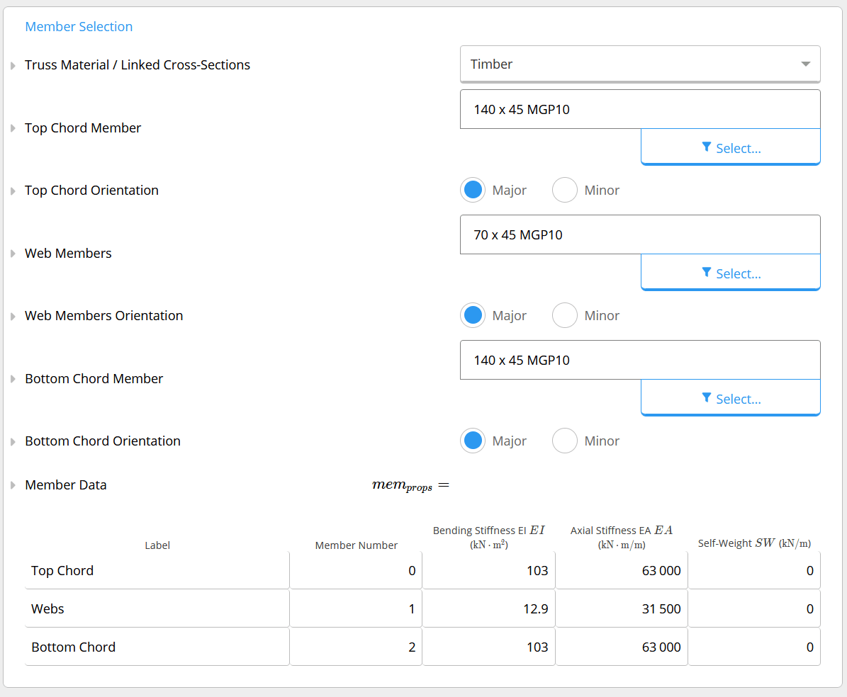
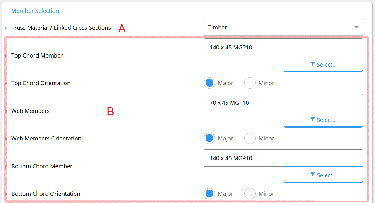
 * Timber components, with both top and bottom chords 140x45 MGP10, and web members 70x45 MGP10, all oriented about their major axes. Note that if you change the member orientation, the bending stiffness (EI) in the table *Member Data* is updated.\\
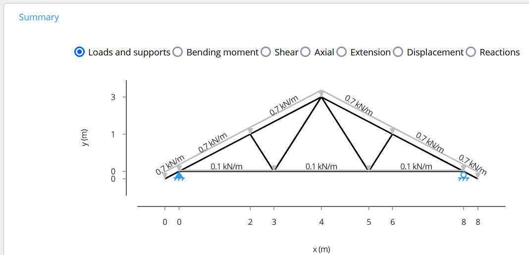
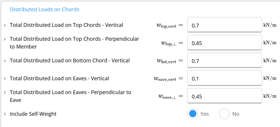
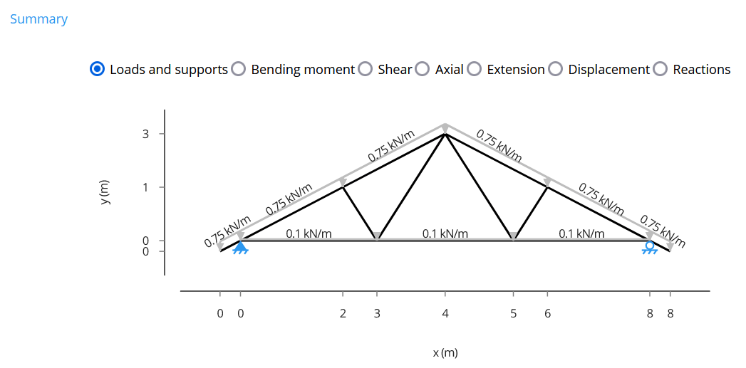
 * Factored dead plus live load of 0.7 kN/m on the top chords, and a factored ceiling dead load of 0.1 kN/m on the bottom chord (vertical loads). You can check the diagram under the *Summary* section to confirm if the loads are correctly applied.\\
 * Factored wind load of 0.45 kN/m on the top chords
*
* Factored wind load of 0.45 kN/m on the top chords
*  The figure below shows the load table, don't forget to check *Yes* for including self-weight.
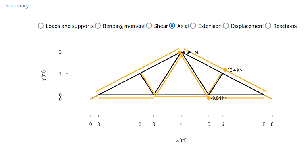
 * Under *Summary,* you can check all results. For axial forces, for example, the results shown in the diagram are confirmed in the table *Overall Results by Member Type.*
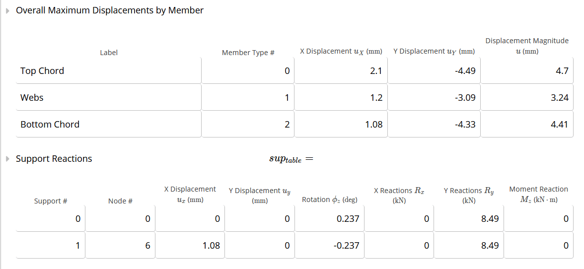
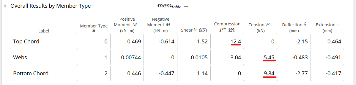 * The displacements and support reactions are also shown in diagrams and tables.\
 \\
\\
 ## Method & scope
| Property | Detail |
| -------------- | -------------------------------------------------------------------------------------------------------------------------------------------- |
| Regions | United States, Australia & New Zealand, Canada, Europe |
| What it checks | Geometry and member modeling, Stiffness assembly and solution, Sign conventions and outputs, Load application, Linking to design calculators |
#### Scope
The Calcs.com Truss Analysis calculator allows users to input the geometry of some common truss types and specify the load conditions on the truss. It then determines the cumulative load applied, support reactions, bending moment, shear and axial forces, extension and displacement for each chord of the truss. Component members of the truss may then be designed by creating a new "Design Only" calculation, and linking it to the truss analysis calculation.
The sheet has 3 main input sections, plus the Summary results section:
1. Truss/Frame Geometry
2. Member Selection
3. Distributed Loads on Chords
4. Summary
This article will explain the expected input parameters in each of those sections and present a worked example of a truss analysis calculation.
#### Calculation method
The Truss Analysis Wizard uses a direct stiffness finite element analysis (FEA) engine to solve any planar 2D truss. You define the geometry, node coordinates, member connectivity, support fixities, and loads, and the solver assembles and inverts the global stiffness matrix to return forces and displacements simultaneously across every member.
##### Geometry and member modeling
Each member is modeled as a two-node axial bar element with user-specified cross-section area (A) and elastic modulus (E). The calculator supports a library of preset truss configurations, Flat Warren, Flat Pratt, Flat Howe, Flat Brown, King Post, Queen Post, Single Fan, Simple Fink, and Fink roof trusses, as well as fully custom node and element definitions. For non-custom configurations, straight chord regions are treated as continuous members rather than pin-jointed segments; this is more accurate but means results may differ slightly from a traditional hand analysis.
##### Stiffness assembly and solution
The solver assembles the global stiffness matrix from the individual element stiffness contributions, applies boundary conditions at pinned and roller supports, and solves the resulting system of linear equations for nodal displacements. Member end forces are back-calculated from the displacements using the element stiffness relation.
##### Sign conventions and outputs
* Positive bending moment indicates that the bottom or right side of the member is in tension.
* Positive axial load indicates a compressive load (compression-positive convention).
Results reported for each member and element include:
* **Axial force**, tension or compression demand in each member
* **Shear force** and **bending moment** envelopes along each element
* **Nodal displacements** and **support reactions**
Output tables include overall results by member type, maximum displacements by member, support reactions, results by element number, and results by node number.
##### Load application
Distributed loads can be applied to chord members. For preset configurations, loads are specified over the chord length; the FEA engine converts these to equivalent nodal contributions automatically. Advanced users can also apply loads directly by element number for non-standard cases. Multiple load cases are evaluated and an envelope of governing demands is reported.
##### Linking to design calculators
The Truss Analysis Wizard is an analysis-only calculator. After solving, member force demands (moment, shear, axial) can be linked directly to Design Only calculators, such as timber, steel, or cold-formed steel beam calculators, so each member is checked against the relevant code without re-entering geometry or loads.
## How to use it
## Method & scope
| Property | Detail |
| -------------- | -------------------------------------------------------------------------------------------------------------------------------------------- |
| Regions | United States, Australia & New Zealand, Canada, Europe |
| What it checks | Geometry and member modeling, Stiffness assembly and solution, Sign conventions and outputs, Load application, Linking to design calculators |
#### Scope
The Calcs.com Truss Analysis calculator allows users to input the geometry of some common truss types and specify the load conditions on the truss. It then determines the cumulative load applied, support reactions, bending moment, shear and axial forces, extension and displacement for each chord of the truss. Component members of the truss may then be designed by creating a new "Design Only" calculation, and linking it to the truss analysis calculation.
The sheet has 3 main input sections, plus the Summary results section:
1. Truss/Frame Geometry
2. Member Selection
3. Distributed Loads on Chords
4. Summary
This article will explain the expected input parameters in each of those sections and present a worked example of a truss analysis calculation.
#### Calculation method
The Truss Analysis Wizard uses a direct stiffness finite element analysis (FEA) engine to solve any planar 2D truss. You define the geometry, node coordinates, member connectivity, support fixities, and loads, and the solver assembles and inverts the global stiffness matrix to return forces and displacements simultaneously across every member.
##### Geometry and member modeling
Each member is modeled as a two-node axial bar element with user-specified cross-section area (A) and elastic modulus (E). The calculator supports a library of preset truss configurations, Flat Warren, Flat Pratt, Flat Howe, Flat Brown, King Post, Queen Post, Single Fan, Simple Fink, and Fink roof trusses, as well as fully custom node and element definitions. For non-custom configurations, straight chord regions are treated as continuous members rather than pin-jointed segments; this is more accurate but means results may differ slightly from a traditional hand analysis.
##### Stiffness assembly and solution
The solver assembles the global stiffness matrix from the individual element stiffness contributions, applies boundary conditions at pinned and roller supports, and solves the resulting system of linear equations for nodal displacements. Member end forces are back-calculated from the displacements using the element stiffness relation.
##### Sign conventions and outputs
* Positive bending moment indicates that the bottom or right side of the member is in tension.
* Positive axial load indicates a compressive load (compression-positive convention).
Results reported for each member and element include:
* **Axial force**, tension or compression demand in each member
* **Shear force** and **bending moment** envelopes along each element
* **Nodal displacements** and **support reactions**
Output tables include overall results by member type, maximum displacements by member, support reactions, results by element number, and results by node number.
##### Load application
Distributed loads can be applied to chord members. For preset configurations, loads are specified over the chord length; the FEA engine converts these to equivalent nodal contributions automatically. Advanced users can also apply loads directly by element number for non-standard cases. Multiple load cases are evaluated and an envelope of governing demands is reported.
##### Linking to design calculators
The Truss Analysis Wizard is an analysis-only calculator. After solving, member force demands (moment, shear, axial) can be linked directly to Design Only calculators, such as timber, steel, or cold-formed steel beam calculators, so each member is checked against the relevant code without re-entering geometry or loads.
## How to use it
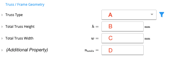 **A. Truss Type**
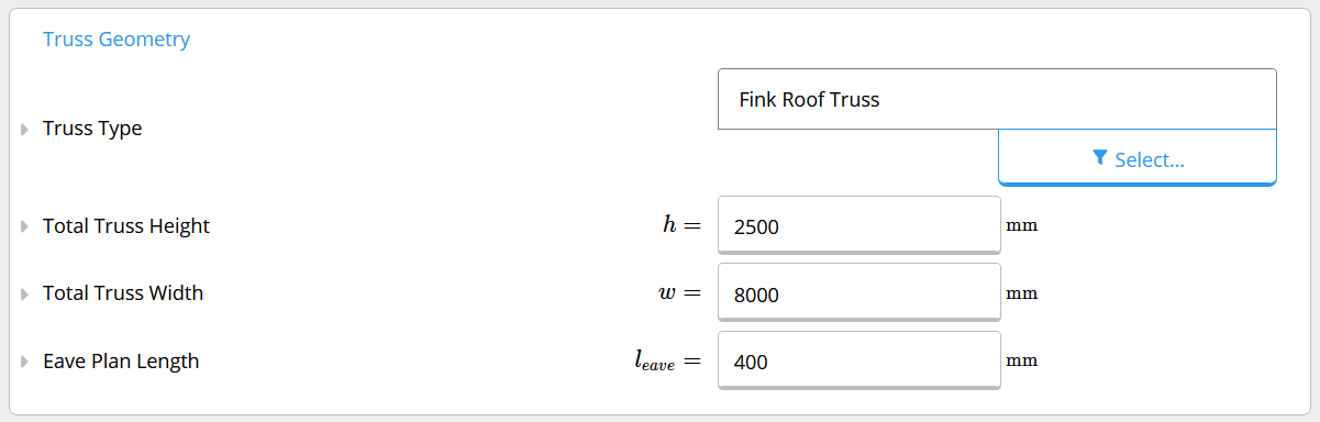
Calcs.com supports a variety of truss types including flat trusses, roof trusses and scissor trusses. For a full list of all the truss types available please refer to our [Truss Types article](/docs/running-calculations/engineering-concepts/truss-types).
A visual diagram of the selected truss type will appear in the summary section, which will update as you input height, width, and loading parameters.
**A. Truss Type**
Calcs.com supports a variety of truss types including flat trusses, roof trusses and scissor trusses. For a full list of all the truss types available please refer to our [Truss Types article](/docs/running-calculations/engineering-concepts/truss-types).
A visual diagram of the selected truss type will appear in the summary section, which will update as you input height, width, and loading parameters.
 **B. Total Truss Height**
The vertical distance from the highest point of the truss to the lowest point of the truss as measured in millimeters (or feet if you are using the Imperial unit system).
**C. Total Truss Width**
The horizontal distance from the left-most point of the truss to the right-most point of the truss as measured in millimeters (or feet if you are using the Imperial unit system).
**D. Additional Property**
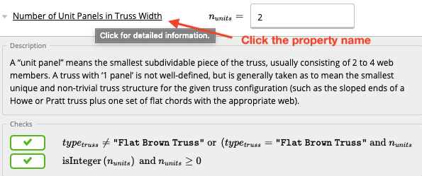
One or more additional properties may also appear, depending upon the specific truss type you've chosen. If you are ever unsure as to what it is asking for, simply click on the property name to obtain a drop-down explanation.
**B. Total Truss Height**
The vertical distance from the highest point of the truss to the lowest point of the truss as measured in millimeters (or feet if you are using the Imperial unit system).
**C. Total Truss Width**
The horizontal distance from the left-most point of the truss to the right-most point of the truss as measured in millimeters (or feet if you are using the Imperial unit system).
**D. Additional Property**
One or more additional properties may also appear, depending upon the specific truss type you've chosen. If you are ever unsure as to what it is asking for, simply click on the property name to obtain a drop-down explanation.
 **A. Truss Material / Linked Cross-Sections**
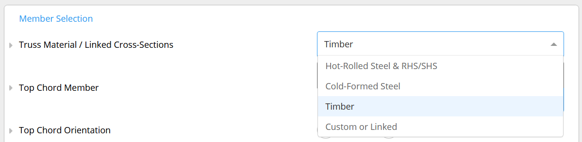
The material out of which your truss has been made. You will be given a drop-down menu, from which you can select the relevant material.
**A. Truss Material / Linked Cross-Sections**
The material out of which your truss has been made. You will be given a drop-down menu, from which you can select the relevant material.
 For Linked Cross-Sections, refer to Section 5 of this article.
**B. Size and Orientation of Truss Members**
Note that this Truss Analysis Wizard is for analysis purposes only. Selecting the right cross-section directly affects the results of the calculations, as they have different stiffnesses and self-weight. As previously mentioned, if you wish to design this member (i.e., pass/fail per code), you will need to create a 'Design Only' calculation and link to this truss analysis calculator (see Section 5).
**Top Chord**
An inclined or horizontal member that marks the upper edge of the truss.
For Linked Cross-Sections, refer to Section 5 of this article.
**B. Size and Orientation of Truss Members**
Note that this Truss Analysis Wizard is for analysis purposes only. Selecting the right cross-section directly affects the results of the calculations, as they have different stiffnesses and self-weight. As previously mentioned, if you wish to design this member (i.e., pass/fail per code), you will need to create a 'Design Only' calculation and link to this truss analysis calculator (see Section 5).
**Top Chord**
An inclined or horizontal member that marks the upper edge of the truss.
 **Bottom Chord**
An inclined or horizontal member that marks the bottom edge of the truss.
**Bottom Chord**
An inclined or horizontal member that marks the bottom edge of the truss.
 **Web Member(s)**
Member/s that join the top and bottom chords to form triangular patterns to give truss actions.
**Web Member(s)**
Member/s that join the top and bottom chords to form triangular patterns to give truss actions.
 **Cross-section**
The size of the top chord, bottom chord and web members need to be specified from drop-down menus. The drop-down menus will automatically display relevant industry-standard sizes for the truss material you specified. You can also use the member selector function to choose a member size. Note that the section sizes and types shown do change depending upon the building standard you are using for the current project. That is, a project using the Australian building standard will show standard Australian sections, and a project using the United States building standard will show standard US sections.
**Orientation**
The orientation of the top chord, bottom chord and web members need to be specified as to whether they are oriented about their major axis or minor axis.
**Cross-section**
The size of the top chord, bottom chord and web members need to be specified from drop-down menus. The drop-down menus will automatically display relevant industry-standard sizes for the truss material you specified. You can also use the member selector function to choose a member size. Note that the section sizes and types shown do change depending upon the building standard you are using for the current project. That is, a project using the Australian building standard will show standard Australian sections, and a project using the United States building standard will show standard US sections.
**Orientation**
The orientation of the top chord, bottom chord and web members need to be specified as to whether they are oriented about their major axis or minor axis.
 A. Total Distributed Loads**
For the first two sections, the total vertical distributed loads for the top chord and bottom chord need to be specified in kN/m (or plf if you are using the Imperial unit system). Depending upon the type of truss selected, inputs may also be available for loads that are perpendicular to the top chord (not vertical i.e., gravity versus aligned loading conditions).
Please note that the subsequent section "Advanced Loads (by Element Number)" can be used to enter loads for individual members, point loads, and angled loads - but most analyses should not require this.
**B. Self-Weight**
You can choose whether or not to include the self-weight of the truss in calculations. The default has been set to include the self-weight of the truss.
A. Total Distributed Loads**
For the first two sections, the total vertical distributed loads for the top chord and bottom chord need to be specified in kN/m (or plf if you are using the Imperial unit system). Depending upon the type of truss selected, inputs may also be available for loads that are perpendicular to the top chord (not vertical i.e., gravity versus aligned loading conditions).
Please note that the subsequent section "Advanced Loads (by Element Number)" can be used to enter loads for individual members, point loads, and angled loads - but most analyses should not require this.
**B. Self-Weight**
You can choose whether or not to include the self-weight of the truss in calculations. The default has been set to include the self-weight of the truss.
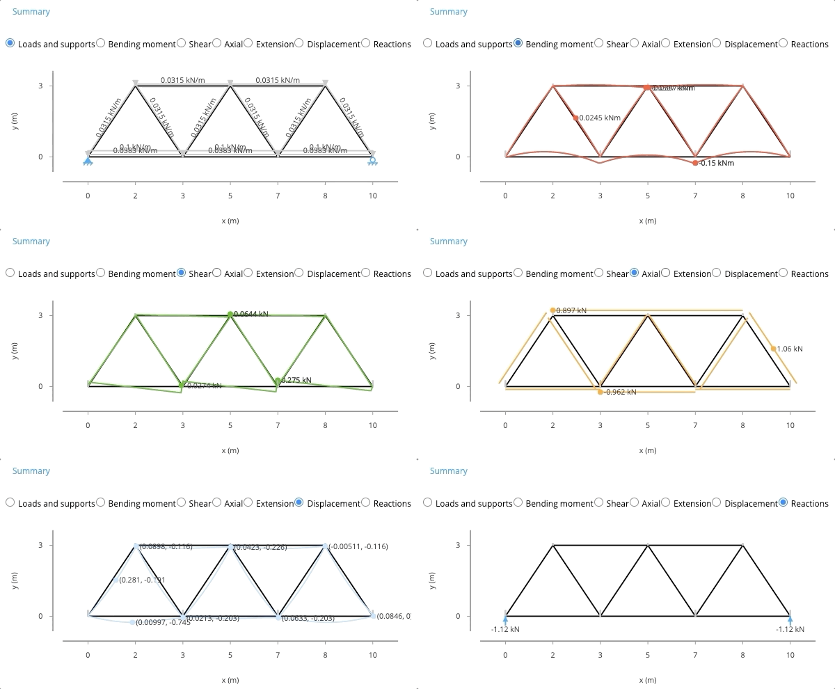 The truss diagram is followed by tables that summarize the calculations and indicate the worst case maximum moments, shears, axial forces, deflections, and extensions for each member type defined. The designer will then use these values to ensure all selected members, connections, etc. are designed to withstand these worst-case loading conditions per code as well as the designer's judgment. If you would like to link to a 'Design Only' calculator to complete your truss design in Calcs.com, see below.
 *
4. In the modal that pops up, select the truss analysis calculation, and then the component of the truss you wish to design (for example, "Top Chord")\
*
4. In the modal that pops up, select the truss analysis calculation, and then the component of the truss you wish to design (for example, "Top Chord")\
 \\
\\
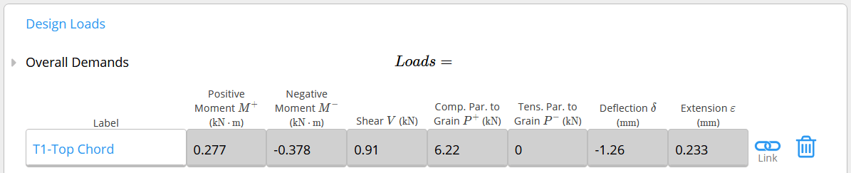 5. Complete the rest of the design as normal, referring to the help documentation for the specific material.
Note that loads on the member will automatically update when you update the truss analysis calculation. However, at this time, the specific section used in the analysis is not linked between the analysis module and the design module and must be selected independently in both calculations. For example, if you select a 140x45 MGP10 in this 'Timber Beam (Design Only)' calculator, you will need to manually ensure that a 140x45 MGP10 is also selected in your Truss Wizard Analysis calculator. Not to worry! Two-way linking will be coming in the future for Calcs.com - our engineering team is already hard at work on this feature.
5. Complete the rest of the design as normal, referring to the help documentation for the specific material.
Note that loads on the member will automatically update when you update the truss analysis calculation. However, at this time, the specific section used in the analysis is not linked between the analysis module and the design module and must be selected independently in both calculations. For example, if you select a 140x45 MGP10 in this 'Timber Beam (Design Only)' calculator, you will need to manually ensure that a 140x45 MGP10 is also selected in your Truss Wizard Analysis calculator. Not to worry! Two-way linking will be coming in the future for Calcs.com - our engineering team is already hard at work on this feature.
