CanadaCSA O86:19NBCC 2015CWC Wood Design Manual 2017
 #### Load Input
 #### Design Conditions Input
 #### Summary and Graphs
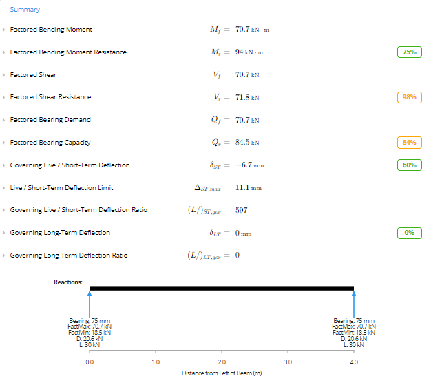
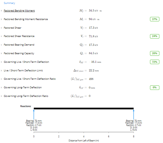
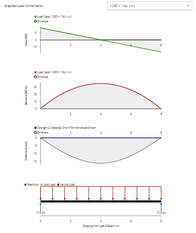
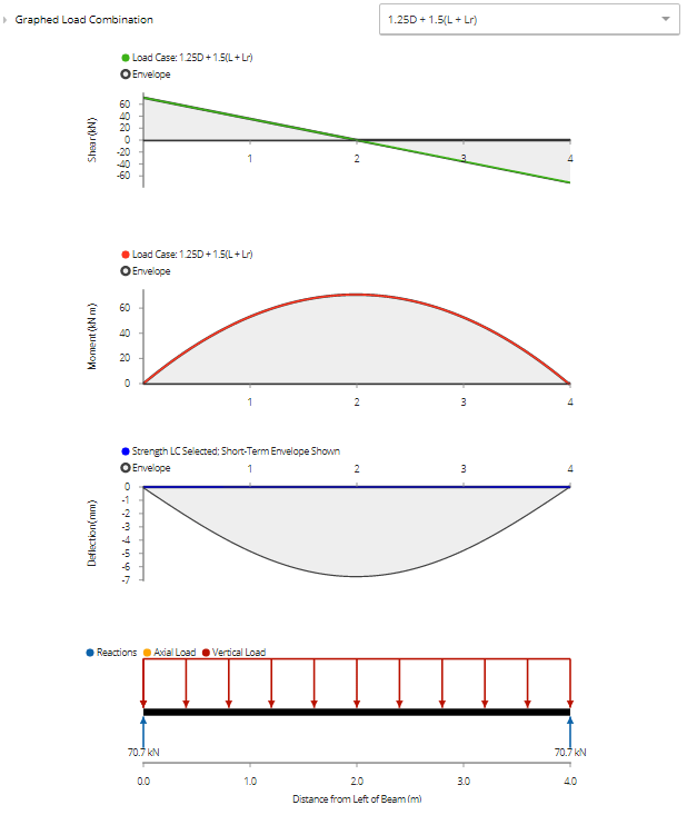 Based on the summary and graphs, you can see that a 7x13.5 \[175x342] 24f-E Douglas Fir glulam beam is suitable for this design scenario based on the governing 1.25D + 1.5(L+Lr) load combination. Looking at the load capacity percentages, a different beam may be suggested as the factored bearing and shear capacities are relatively high.
##### *Access the full PDF file here:* [*\[CA\] Wood Beam Example*](https://s3.amazonaws.com/helpscout.net/docs/assets/5c09df402c7d3a31944ed720/attachments/613f8f5c2b380503dfdf0a41/How-to-Design-a-Wood-Beam,-Joist,-and-Girder-to-CSA-O86.pdf)
## Method & scope
| Property | Detail |
| ---------------- | ------------------------------------------------------------------------------------------------------------------------------------------------------------------------------------------------------------ |
| Design standards | CSA O86:19, NBCC 2015, CWC Wood Design Manual 2017 |
| Regions | Canada |
| Presets | Generic Beam, Floor Joist, Floor Girder, Ceiling Joist, Ridge Beam, Roof Header, Floor Header, Combination Beam |
| What it checks | Structural model and load combinations, Bending moment resistance (CSA O86:19 Cl.7), Shear resistance (CSA O86:19 Cl.6.5.4.3), Bearing capacity, Deflection checks (CSA O86:19 Cl.5.4.2 / NBCC Commentary D) |
#### See the exact clause
Based on the summary and graphs, you can see that a 7x13.5 \[175x342] 24f-E Douglas Fir glulam beam is suitable for this design scenario based on the governing 1.25D + 1.5(L+Lr) load combination. Looking at the load capacity percentages, a different beam may be suggested as the factored bearing and shear capacities are relatively high.
##### *Access the full PDF file here:* [*\[CA\] Wood Beam Example*](https://s3.amazonaws.com/helpscout.net/docs/assets/5c09df402c7d3a31944ed720/attachments/613f8f5c2b380503dfdf0a41/How-to-Design-a-Wood-Beam,-Joist,-and-Girder-to-CSA-O86.pdf)
## Method & scope
| Property | Detail |
| ---------------- | ------------------------------------------------------------------------------------------------------------------------------------------------------------------------------------------------------------ |
| Design standards | CSA O86:19, NBCC 2015, CWC Wood Design Manual 2017 |
| Regions | Canada |
| Presets | Generic Beam, Floor Joist, Floor Girder, Ceiling Joist, Ridge Beam, Roof Header, Floor Header, Combination Beam |
| What it checks | Structural model and load combinations, Bending moment resistance (CSA O86:19 Cl.7), Shear resistance (CSA O86:19 Cl.6.5.4.3), Bearing capacity, Deflection checks (CSA O86:19 Cl.5.4.2 / NBCC Commentary D) |
#### See the exact clause
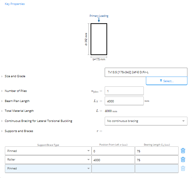
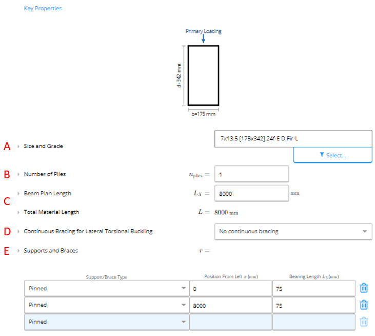 **A. Size and Grade**
In Calcs.com, you can select the size of the member you want from a list of industry-standard sized members by using the “Select” button. Using the corresponding filters, you can view available options based on the chosen type, species, grade, manufacturer, and nominal size.
**A. Size and Grade**
In Calcs.com, you can select the size of the member you want from a list of industry-standard sized members by using the “Select” button. Using the corresponding filters, you can view available options based on the chosen type, species, grade, manufacturer, and nominal size.
 **B. Number of Plies**
The number of wood plies or boards in the beam. You need to have at least one board in your beam.
**C. Beam Plan Length**
The Beam Plan Length is equal to the length of the beam.
**D. Continuous Bracing For Lateral Torsional Buckling**
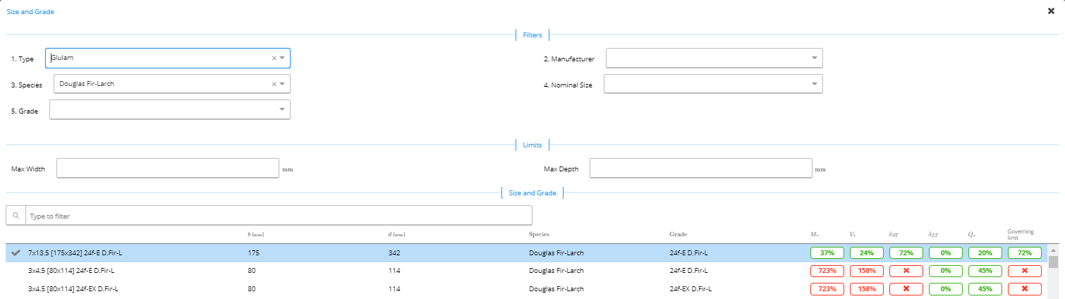
You need to specify whether your beam has no continuous bracing, bracing continuous at the top edge only, bracing continuous at the bottom edge, or both. For sawn lumber, when you specify continuous bracing, Calcs.com will provide you with a short description of the CSA O86 requirements for bracing based on the width to depth ratio.
**B. Number of Plies**
The number of wood plies or boards in the beam. You need to have at least one board in your beam.
**C. Beam Plan Length**
The Beam Plan Length is equal to the length of the beam.
**D. Continuous Bracing For Lateral Torsional Buckling**
You need to specify whether your beam has no continuous bracing, bracing continuous at the top edge only, bracing continuous at the bottom edge, or both. For sawn lumber, when you specify continuous bracing, Calcs.com will provide you with a short description of the CSA O86 requirements for bracing based on the width to depth ratio.
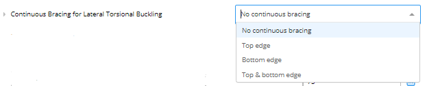 **E. Position of Supports**
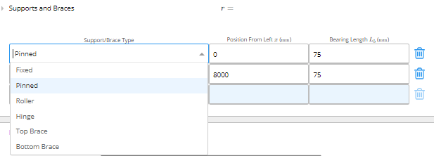
This section is where you can select the support type or bracing type from a drop-down menu and then specify the location of each support/brace in millimeters (mm) or feet (ft) as measured from the leftmost position of the beam. Additionally, for each support, you must specify a bearing length in millimeters (mm) or inches (in) for a simple bearing check. To ignore bearing checks, simply enter a bearing length of 0.
**E. Position of Supports**
This section is where you can select the support type or bracing type from a drop-down menu and then specify the location of each support/brace in millimeters (mm) or feet (ft) as measured from the leftmost position of the beam. Additionally, for each support, you must specify a bearing length in millimeters (mm) or inches (in) for a simple bearing check. To ignore bearing checks, simply enter a bearing length of 0.
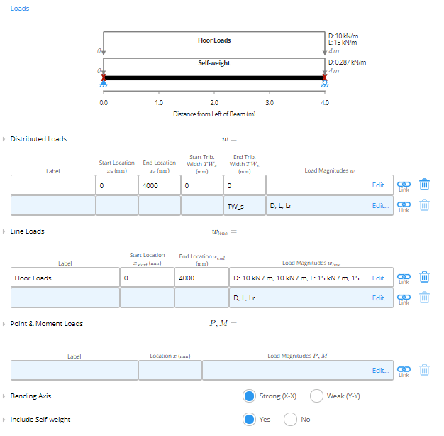
 **A. Load Diagram**
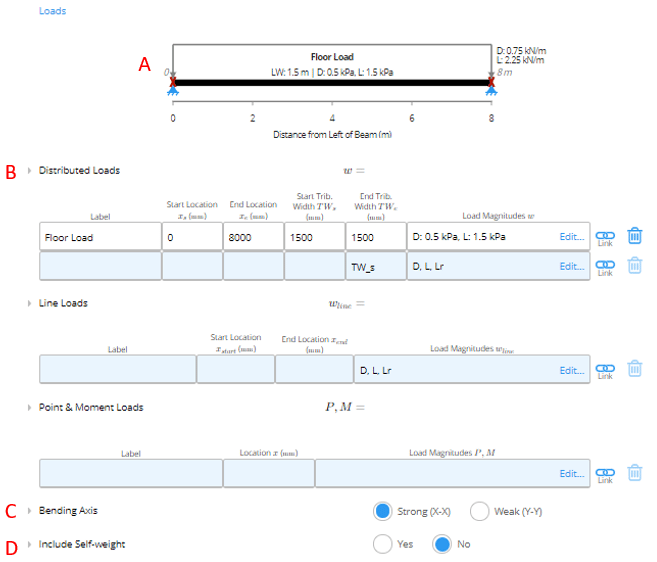
The load diagram provides a live illustration of the beam and the assigned loading.
**B. Loads**
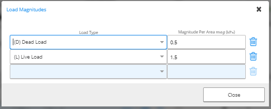
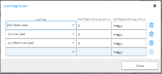
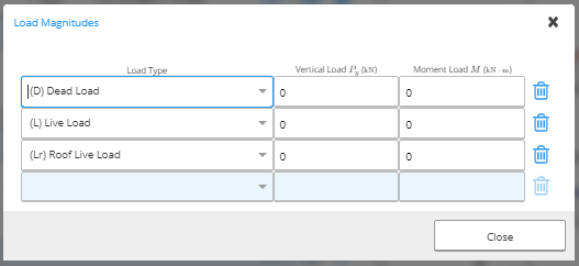
Loads can be input as distributed, line, point, and moment loads in this section using the corresponding tables. You need to specify the location of the load in millimeters (mm) or inches (in) from the leftmost position and the respective load magnitude. To input load magnitude, select the load magnitude box or click the "Edit" text. For each corresponding load, a load magnitude table will appear where you will specify the type of load (Dead, Live, etc) and the respective magnitude in metric or imperial units.
**A. Load Diagram**
The load diagram provides a live illustration of the beam and the assigned loading.
**B. Loads**
Loads can be input as distributed, line, point, and moment loads in this section using the corresponding tables. You need to specify the location of the load in millimeters (mm) or inches (in) from the leftmost position and the respective load magnitude. To input load magnitude, select the load magnitude box or click the "Edit" text. For each corresponding load, a load magnitude table will appear where you will specify the type of load (Dead, Live, etc) and the respective magnitude in metric or imperial units.
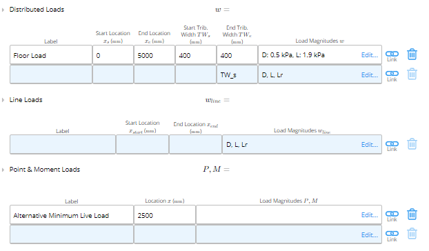 Load Magnitude table for Distributed Loads (kiloPascals (kPa) or pounds per square foot (psf))
 Load Magnitude table for Line Loads (kiloNewtons per meter (kN/m) or pounds per linear foot (plf)
 Load Magnitude table for Point/Moment Loads (kiloNewtons (kN) or pounds (lb) and kiloNewton-meter (kN\*m) or pound-feet (lb\*ft))
 **C. Bending Axis**
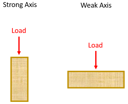
Calcs.com requires you to specify if the beam is being loaded on the strong or weak axis. Calcs.com sets the default to the strong axis / joist (X-X). The strong axis corresponds to joist orientation and the weak axis to plank orientation.
**C. Bending Axis**
Calcs.com requires you to specify if the beam is being loaded on the strong or weak axis. Calcs.com sets the default to the strong axis / joist (X-X). The strong axis corresponds to joist orientation and the weak axis to plank orientation.
 **D. Self-Weight**
ClearCallcs allows you to choose to include or exclude the self-weight of the beam in your calculations. The calculator is set to include the self-weight by default unless you specify otherwise. This can play a difference if you're comparing against a published span table, where the self-weight of joists is often included in the superimposed dead load.
**D. Self-Weight**
ClearCallcs allows you to choose to include or exclude the self-weight of the beam in your calculations. The calculator is set to include the self-weight by default unless you specify otherwise. This can play a difference if you're comparing against a published span table, where the self-weight of joists is often included in the superimposed dead load.
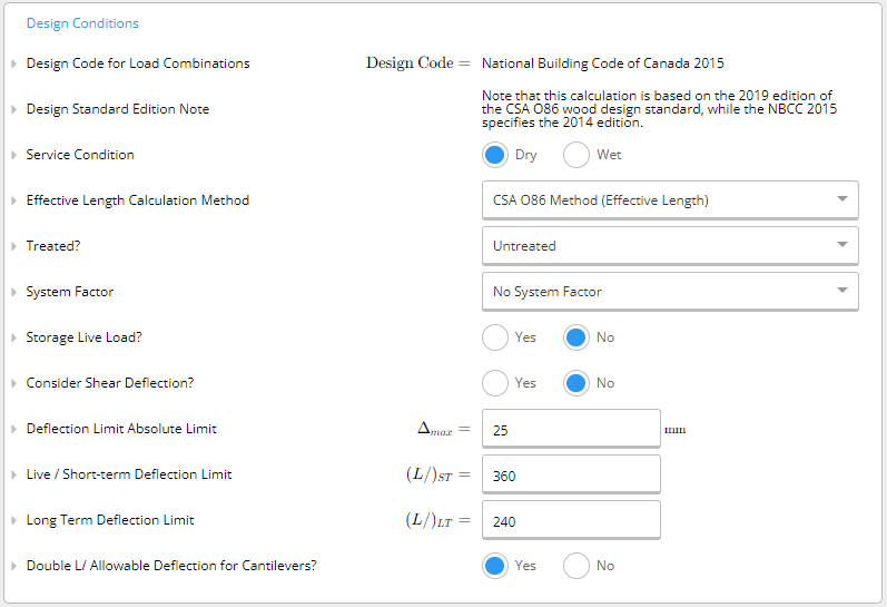
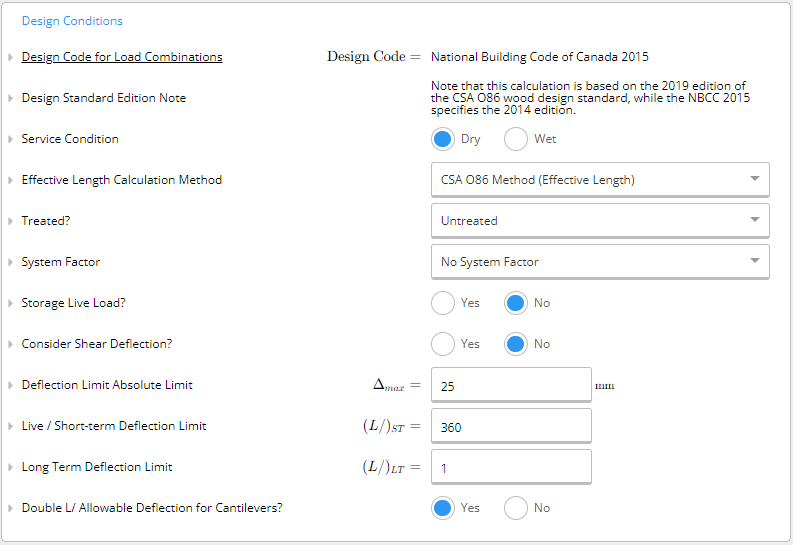 * **Service Condition:** You need to indicate if the service condition is 'dry' or 'wet.' It is considered wet if the moisture content of wood will exceed 19% for an extended time. Typically, wet conditions apply to most exterior uses.
* **Effective Length Calculation Method**: By default, Calcs.com uses the effective length calculation outlined by CSA O86:19, however, we conservatively take the effective length as 1.92L regardless of the loading condition. For a more accurate calculation, Calcs.com also provides you with the option to use the quarter-moment method outlined by the [American Wood Council Technical Report 14.](https://awc.org/codes-standards/publications/tr14)
* **Treatment:** Calcs.com requires you to indicate if the wood beam is untreated, or if it is preservative-treated and whether it is incised (partially cut) or unincised.
* **System Factor:** A system factor is considered if the member is part of a system where loads can be shared. There are three options for sawn lumber:
* * No System Factor: There are less than 3 beams spaced 610 mm apart and/or are not mutually sharing loads
* Case 1 (for systems that don't meet Case 2 requirements): There are more than 3 beams spaced less than 610 mm apart, mutually sharing loads
* Case 2 (typical for joists and rafters): All of the following conditions are met
* There are more than 3 beams spaced less than 610 mm apart, mutually sharing the load
* Members are sheathed with a minimum of 9.5 mm OSB, waferboard, plywood or with min. 17mm lumber with panel coverings.
* The sheathing is attached with sufficient stiffness and adequate spacing equal to 2 common nails at 150 mm on center at edges and 300 mm on center elsewhere.
* For glulams and LVL's the option is simply whether to consider a system factor or not - generally it can be considered if more than three parallel members are sharing load.
* **Storage Live Load:** A storage live load is a live load (loads due to occupancy use) that occurs for a long duration. An example of this is storage in an attic. If this is set to yes, the duration factor associated with live load will be taken the same as dead load, and the load factor on live load will be increased in some combinations.
* **Consider Shear Deflection:** Shear deflection can be a significant component of total deflection due to the low shear modulus. In particular, specifications for structural composites such as LVL often require that shear deflection be directly accounted for. If this is set to “Yes”, we use an approximation based on the peak moment within a span to find the shear deflection. This gives exact results for simply supported and cantilever spans with either a point load in the center or a UDL.
* **Absolute Deflection Limit:** The maximum allowable deflection for the beam in millimeters (mm) or inches (in).
* **Live/Short-term Deflection Ratio:** The maximum allowable deflection ratio for live and short loading. The default is L/360 but you may change this to a preferred ratio.
* **Long Term Deflection Ratio:** The maximum allowable deflection ratio for long-term loading. The default is L/240 but you may change this to a preferred ratio.
* **Double Length/Allowable Deflection for Cantilevers:** For cantilever spans, it's typical to take "L" as double the span length. To adjust for this, the allowable deflection can be doubled.
* **Service Condition:** You need to indicate if the service condition is 'dry' or 'wet.' It is considered wet if the moisture content of wood will exceed 19% for an extended time. Typically, wet conditions apply to most exterior uses.
* **Effective Length Calculation Method**: By default, Calcs.com uses the effective length calculation outlined by CSA O86:19, however, we conservatively take the effective length as 1.92L regardless of the loading condition. For a more accurate calculation, Calcs.com also provides you with the option to use the quarter-moment method outlined by the [American Wood Council Technical Report 14.](https://awc.org/codes-standards/publications/tr14)
* **Treatment:** Calcs.com requires you to indicate if the wood beam is untreated, or if it is preservative-treated and whether it is incised (partially cut) or unincised.
* **System Factor:** A system factor is considered if the member is part of a system where loads can be shared. There are three options for sawn lumber:
* * No System Factor: There are less than 3 beams spaced 610 mm apart and/or are not mutually sharing loads
* Case 1 (for systems that don't meet Case 2 requirements): There are more than 3 beams spaced less than 610 mm apart, mutually sharing loads
* Case 2 (typical for joists and rafters): All of the following conditions are met
* There are more than 3 beams spaced less than 610 mm apart, mutually sharing the load
* Members are sheathed with a minimum of 9.5 mm OSB, waferboard, plywood or with min. 17mm lumber with panel coverings.
* The sheathing is attached with sufficient stiffness and adequate spacing equal to 2 common nails at 150 mm on center at edges and 300 mm on center elsewhere.
* For glulams and LVL's the option is simply whether to consider a system factor or not - generally it can be considered if more than three parallel members are sharing load.
* **Storage Live Load:** A storage live load is a live load (loads due to occupancy use) that occurs for a long duration. An example of this is storage in an attic. If this is set to yes, the duration factor associated with live load will be taken the same as dead load, and the load factor on live load will be increased in some combinations.
* **Consider Shear Deflection:** Shear deflection can be a significant component of total deflection due to the low shear modulus. In particular, specifications for structural composites such as LVL often require that shear deflection be directly accounted for. If this is set to “Yes”, we use an approximation based on the peak moment within a span to find the shear deflection. This gives exact results for simply supported and cantilever spans with either a point load in the center or a UDL.
* **Absolute Deflection Limit:** The maximum allowable deflection for the beam in millimeters (mm) or inches (in).
* **Live/Short-term Deflection Ratio:** The maximum allowable deflection ratio for live and short loading. The default is L/360 but you may change this to a preferred ratio.
* **Long Term Deflection Ratio:** The maximum allowable deflection ratio for long-term loading. The default is L/240 but you may change this to a preferred ratio.
* **Double Length/Allowable Deflection for Cantilevers:** For cantilever spans, it's typical to take "L" as double the span length. To adjust for this, the allowable deflection can be doubled.
 Additionally, in the associated tabs, below design conditions, you can see the respective parameters used to derive the summary figures and calculations. These include the following.
* Load Combination Analysis
* Unfactored Load Combination Analysis
* Modulus of Elasticity (CSA O86:19 Section 6.3)
* Bending Moment Resistance (CSA O86:19 Section 6.5.3)
* Positive Bending (CSA O86:19 Section 6.5.3)
* Negative Bending (CSA O86:19 Section 6.5.3)
* Shear Resistance (CSA O86:19 Section 6.5.4)
* Bearing (Compressive Resistance Perpendicular to Grain) (CSA O86:19 Section 6.5.6)
* Deflections
These parameters were calculated based on the input loads and key properties.
Additionally, in the associated tabs, below design conditions, you can see the respective parameters used to derive the summary figures and calculations. These include the following.
* Load Combination Analysis
* Unfactored Load Combination Analysis
* Modulus of Elasticity (CSA O86:19 Section 6.3)
* Bending Moment Resistance (CSA O86:19 Section 6.5.3)
* Positive Bending (CSA O86:19 Section 6.5.3)
* Negative Bending (CSA O86:19 Section 6.5.3)
* Shear Resistance (CSA O86:19 Section 6.5.4)
* Bearing (Compressive Resistance Perpendicular to Grain) (CSA O86:19 Section 6.5.6)
* Deflections
These parameters were calculated based on the input loads and key properties.
