> ## Documentation Index
> Fetch the complete documentation index at: https://calcs.com/docs/llms.txt
> Use this file to discover all available pages before exploring further.
# Design a Steel Beam to EN 1993 (Eurocode 3)
> Design steel beams to EN 1993-1-1:2005 (Eurocode 3) with unlimited spans and loads. Checks bending, LTB, shear, web buckling and deflection.
EuropeEN 1993-1-5:2006SCI Publication P360 (2011)
Beam reactions link to column and footing calculations automatically. Design steel beams to Eurocode 3 (EN 1993-1-1) with unlimited spans and loads, checks cover section capacity in bending, lateral torsional buckling, shear resistance, shear web buckling, and three EN 1990 deflection limits.
#### Background
The EU steel beam calculator can be used to calculate both the demands as well as the resistance of a straight beam.\
The analysis capabilities include:
* Point transverse forces and point uni-axial moments (excluding torsion)
* Line Loads (including linearly varying)
* Distributed Loads (including varying tributary width). For details on tributary widths, refer article [170-what-is-tributary-width](/docs/running-calculations/setting-up-a-calculation/loads/what-is-tributary-width)
The design capabilities include:
* Cross Section Classification (Class 4 section design not available)
* ULS: Moment Resistance (EN 1993-1-1:2005 Cl 6.2.5)
* ULS: Shear Resistance (EN 1993-1-1:2005 Cl 6.2.6)
* ULS: Buckling Resistance of Uniform Member in Bending (EN 1993-1-1:2005 Cl 6.3.2)
* ULS: Buckling Resistance of Uniform Member in Shear (EN 1993-1-5:2006 Cl 5.1-5.5) including transverse stiffeners.
* SLS: Deflection analysis
* Penetrations or fastener holes (checks if they may be ignored)
#### Tutorial
In this worked design example, we will go through the design process of a two-span continuous steel beam. It will be an interior beam, holding a 150mm concrete slab and a regular office live load. The first span is 6m long and the second one is 4m long. Beam spacing is at every 3m feet, and the beam is laterally restrained only at supports.
## Method & scope
| Property | Detail |
| ---------------- | --------------------------------------------------------------------------------------------------------------------------------------------------------------------------------------------------------------------------------------------------------------------------------------------------------------------------------------------------- |
| Design standards | EN 1993-1-1:2005 (Eurocode 3), EN 1993-1-5:2006, SCI Publication P360 (2011), JRC (2007) Commentary and Worked Examples to EN 1993-1-5 |
| Regions | Europe |
| Presets | Generic Beam, Rafter, Roof Bearer, Underpurlin, Strutting / Counter-Strutting Beam, Verandah Beam, Hanging Beam, Ceiling Joist, and 4 more |
| What it checks | Structural model and load combinations, Cross-section classification (EN 1993-1-1:2005 Cl 5.5.2), Section bending capacity (EN 1993-1-1:2005 Cl 6.2.5), Shear resistance (EN 1993-1-1:2005 Cl 6.2.6), Shear buckling (EN 1993-1-5:2006 Cl 5.5), Lateral torsional buckling (EN 1993-1-1:2005 Cl 6.3.2.1), Deflection checks (EN 1990:2002 Cl 6.5.3) |
#### Design Criteria
Deflection limits values are to be entered depending upon the national annex and depending upon the use of the structure. In our case, we shall assume the structure is designed according to Table NA.2 BS EN1993-1-1:2014 (UK annex) and carries a plaster ceiling. Therefore, the characteristic load combination due to variable load only is span / 360.
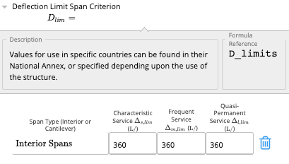 The absolute criterion can be adjusted that set a hard limit on any deflections. This may be set project-wide in your Project Defaults or can be manually set for this structure.
#### Assumptions and Limitations
* Beams are computed by a chosen limit state and load combination. It is up to the user to choose limit states to determine the worst loading case combination. These may be viewed and/or modified in Project Defaults.
#### See the exact clause
Every check in this calculator links back to its governing clause in EN 1993. Open the **Formula Reference** panel on any result and select the clause reference to read it. See [Viewing Clauses from Inside a Calculator](/docs/running-calculations/standards-and-codes/viewing-clauses-from-inside-calculator).
#### Calculation method
##### Structural model and load combinations
The calculator models the steel beam as a one-dimensional element and computes bending moment, shear, and deflection diagrams under each EN 1990:2002 load combination. Loads are entered by type, permanent (G), variable (Q), wind (W), snow (S), and the calculator generates governing ULS and three SLS combinations:
* **Characteristic (irreversible)**: G + Q\_k + psi\_0 × other variable loads
* **Frequent (reversible)**: G + psi\_1 × Q\_1 + psi\_2 × other
* **Quasi-permanent (long-term)**: G + psi\_2 × Q
##### Cross-section classification (EN 1993-1-1:2005 Cl 5.5.2)
Before computing capacities, the calculator classifies the cross-section (Class 1 through 4) by checking the flange and web slenderness limits against epsilon = sqrt(235/fy). This governs whether the plastic, elastic, or effective section modulus is used for bending resistance.
##### Section bending capacity (EN 1993-1-1:2005 Cl 6.2.5)
Bending resistance M\_c,Rd uses the plastic section modulus W\_pl for Class 1 and 2 sections, the elastic section modulus W\_el for Class 3, or the effective modulus W\_eff for Class 4:
**bending utilization** = M\_Ed / M\_c,Rd ≤ 1.0
##### Shear resistance (EN 1993-1-1:2005 Cl 6.2.6)
The plastic shear resistance V\_pl,Rd is computed from the shear area A\_v (the web area for I-sections) and the yield strength fy. For webs with hw/tw ≥ 72 epsilon/eta, shear buckling governs and the check moves to EN 1993-1-5.
**shear utilization** = V\_Ed / V\_Rd ≤ 1.0
##### Shear buckling (EN 1993-1-5:2006 Cl 5.5)
For slender webs, shear buckling resistance V\_b,Rd is computed using the contribution method, adding flange and web contributions. The web buckling coefficient k\_tau depends on the panel aspect ratio a/hw between transverse stiffeners. The combined bending-and-shear interaction is then checked per EN 1993-1-1:2005 Cl 7.1 Eq 7.1.
##### Lateral torsional buckling (EN 1993-1-1:2005 Cl 6.3.2.1)
LTB resistance M\_b,Rd is computed from the critical elastic moment M\_cr and the reduction factor chi\_LT. The relative slenderness lambda\_LT is derived from M\_cr, which accounts for the unbraced length, moment gradient, and section properties (I\_w, I\_T, I\_z, EI). The reduction factor chi\_LT reduces the cross-section moment resistance based on the imperfection factor for the LTB buckling curve applicable to the section.
**LTB utilization** = M\_Ed / M\_b,Rd ≤ 1.0
##### Deflection checks (EN 1990:2002 Cl 6.5.3)
Three independent deflection limit states are verified per span, using the characteristic, frequent, and quasi-permanent serviceability combinations respectively. Each is checked against a user-defined span/n ratio and an optional absolute limit in mm.
##### Load linking
Support reactions are exported as linked outputs. Connected column and footing calculations placed downstream in the same project receive updated reactions automatically whenever the beam inputs change.
## How to use it
First, we enter the key properties of our beam:
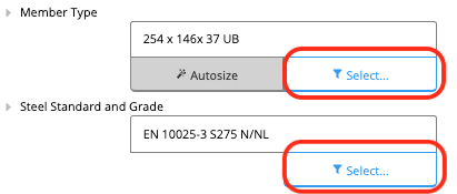
* *Member Type & Steel Grade* - Clicking "Select" will open a list of all properties and allow you to select an initial size and grade. Refer to related article [Quickly finding the best section with the member selector](/docs/running-calculations/member-selector/index)\\
The absolute criterion can be adjusted that set a hard limit on any deflections. This may be set project-wide in your Project Defaults or can be manually set for this structure.
#### Assumptions and Limitations
* Beams are computed by a chosen limit state and load combination. It is up to the user to choose limit states to determine the worst loading case combination. These may be viewed and/or modified in Project Defaults.
#### See the exact clause
Every check in this calculator links back to its governing clause in EN 1993. Open the **Formula Reference** panel on any result and select the clause reference to read it. See [Viewing Clauses from Inside a Calculator](/docs/running-calculations/standards-and-codes/viewing-clauses-from-inside-calculator).
#### Calculation method
##### Structural model and load combinations
The calculator models the steel beam as a one-dimensional element and computes bending moment, shear, and deflection diagrams under each EN 1990:2002 load combination. Loads are entered by type, permanent (G), variable (Q), wind (W), snow (S), and the calculator generates governing ULS and three SLS combinations:
* **Characteristic (irreversible)**: G + Q\_k + psi\_0 × other variable loads
* **Frequent (reversible)**: G + psi\_1 × Q\_1 + psi\_2 × other
* **Quasi-permanent (long-term)**: G + psi\_2 × Q
##### Cross-section classification (EN 1993-1-1:2005 Cl 5.5.2)
Before computing capacities, the calculator classifies the cross-section (Class 1 through 4) by checking the flange and web slenderness limits against epsilon = sqrt(235/fy). This governs whether the plastic, elastic, or effective section modulus is used for bending resistance.
##### Section bending capacity (EN 1993-1-1:2005 Cl 6.2.5)
Bending resistance M\_c,Rd uses the plastic section modulus W\_pl for Class 1 and 2 sections, the elastic section modulus W\_el for Class 3, or the effective modulus W\_eff for Class 4:
**bending utilization** = M\_Ed / M\_c,Rd ≤ 1.0
##### Shear resistance (EN 1993-1-1:2005 Cl 6.2.6)
The plastic shear resistance V\_pl,Rd is computed from the shear area A\_v (the web area for I-sections) and the yield strength fy. For webs with hw/tw ≥ 72 epsilon/eta, shear buckling governs and the check moves to EN 1993-1-5.
**shear utilization** = V\_Ed / V\_Rd ≤ 1.0
##### Shear buckling (EN 1993-1-5:2006 Cl 5.5)
For slender webs, shear buckling resistance V\_b,Rd is computed using the contribution method, adding flange and web contributions. The web buckling coefficient k\_tau depends on the panel aspect ratio a/hw between transverse stiffeners. The combined bending-and-shear interaction is then checked per EN 1993-1-1:2005 Cl 7.1 Eq 7.1.
##### Lateral torsional buckling (EN 1993-1-1:2005 Cl 6.3.2.1)
LTB resistance M\_b,Rd is computed from the critical elastic moment M\_cr and the reduction factor chi\_LT. The relative slenderness lambda\_LT is derived from M\_cr, which accounts for the unbraced length, moment gradient, and section properties (I\_w, I\_T, I\_z, EI). The reduction factor chi\_LT reduces the cross-section moment resistance based on the imperfection factor for the LTB buckling curve applicable to the section.
**LTB utilization** = M\_Ed / M\_b,Rd ≤ 1.0
##### Deflection checks (EN 1990:2002 Cl 6.5.3)
Three independent deflection limit states are verified per span, using the characteristic, frequent, and quasi-permanent serviceability combinations respectively. Each is checked against a user-defined span/n ratio and an optional absolute limit in mm.
##### Load linking
Support reactions are exported as linked outputs. Connected column and footing calculations placed downstream in the same project receive updated reactions automatically whenever the beam inputs change.
## How to use it
First, we enter the key properties of our beam:
* *Member Type & Steel Grade* - Clicking "Select" will open a list of all properties and allow you to select an initial size and grade. Refer to related article [Quickly finding the best section with the member selector](/docs/running-calculations/member-selector/index)\\
 * *Total Beam Length* - The length between start and end of the beam, irrespective of the support conditions.
* *Length between lateral restraints* - Let’s conservatively assume that the beam is only braced at supports, so the length between lateral restraints is equal to our maximum beam span of 6m. We can also enter "L\_maxspan", which will always default to the largest span between supports, as shown below:
*
* *Total Beam Length* - The length between start and end of the beam, irrespective of the support conditions.
* *Length between lateral restraints* - Let’s conservatively assume that the beam is only braced at supports, so the length between lateral restraints is equal to our maximum beam span of 6m. We can also enter "L\_maxspan", which will always default to the largest span between supports, as shown below:
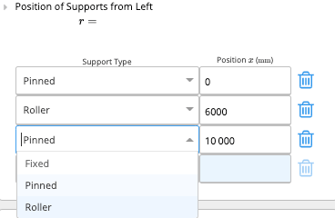
*  *Position of Supports from Left* - The support conditions may be at any position along the beam. A cantilever can be created on either end by moving the support condition away from "0" or the "Total Beam Length"
 We enter the tributary width as 3 meters. For dead load, we have a 150mm concrete slab (3.6 kPa for 2400 kg/m3 density) and a 1.2 kPa super-imposed dead load. We can let Calcs.com calculate the dead load in PSF by entering in the weight of concrete and multiplying by the slab thickness. Calcs.com will resolve the units and warn you if you are using incorrect units.
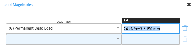 For the office loads we use BS EN1993-1-1:2002 Table 6.2 (For Category B, 2.0kPa to 3.0kPa may be used). For the imposed loads, 1.2 kPa is used for other imposed loads such as tiling or
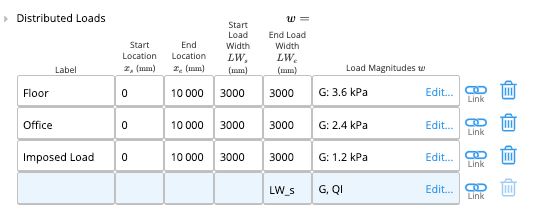 Self-weight may be automatically calculated using the self-weight toggle.
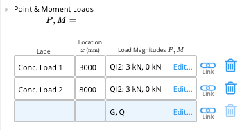
 Now Table 6.2 BS EN1993-1-1:2002 also requires that we apply a 1.5 to 4.5 kN concentrated load for measuring local effects in office spaces. This load doesn’t occur at the same time as the uniformly distributed live load. In this case, it’s pretty clear that it won’t govern, but we will still apply for the example. Since the concentrated load doesn’t apply at the same time as the UDL, we’ll apply it in the “Point & Moment Loads” section.
We apply the loads at the mid-span locations (3000mm and 8000mm). Note how we enter the load type as “L2” in this case. This means that the internal FEA solver will apply “QI” and “QI2” separately, and output the envelope of each case.
Now Table 6.2 BS EN1993-1-1:2002 also requires that we apply a 1.5 to 4.5 kN concentrated load for measuring local effects in office spaces. This load doesn’t occur at the same time as the uniformly distributed live load. In this case, it’s pretty clear that it won’t govern, but we will still apply for the example. Since the concentrated load doesn’t apply at the same time as the UDL, we’ll apply it in the “Point & Moment Loads” section.
We apply the loads at the mid-span locations (3000mm and 8000mm). Note how we enter the load type as “L2” in this case. This means that the internal FEA solver will apply “QI” and “QI2” separately, and output the envelope of each case.
 We can now verify that our loads are all properly placed:
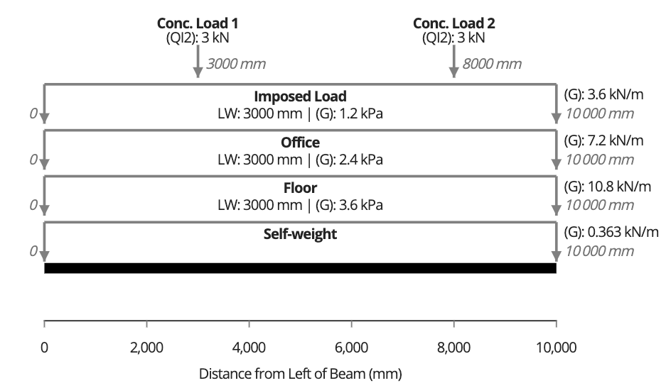 Note that the loads shown here are, by default, unfactored under the 1.35G + 1.5Q load combination. The load combination can easily be changed with the dropdown above the graphics.
At this point, we are ready to revise our member size. We go back to our "Member Type" tab and search for a utilization close to but not exceeding 100 %:
Note that the loads shown here are, by default, unfactored under the 1.35G + 1.5Q load combination. The load combination can easily be changed with the dropdown above the graphics.
At this point, we are ready to revise our member size. We go back to our "Member Type" tab and search for a utilization close to but not exceeding 100 %:
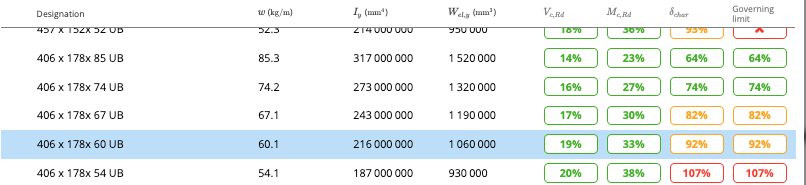 The four right-most columns indicate the utilization for the three governing modes – shear, moment, characteristic deflection, and governing. The governing column considers all checks and validation requirements within the entire calculation. Ideally, we want the minimal weight section that will satisfy all three modes. It is then a matter of scrolling to find the best cross-section. Looking through, we find two candidates – 406 x 178 x 67 UB and 457 x 152 x 60 UB. We pick the shorter section even though it is slightly heavier, so as to reduce the required floor thickness.
That’s it! We’ve now designed our beam!
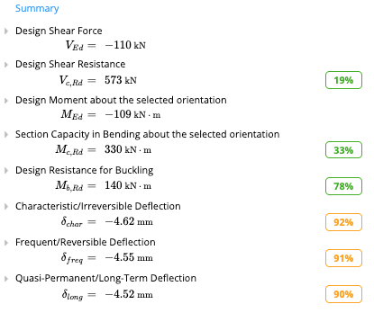
Once we’ve got our beam design, we can quickly glance at relevant values to make sure everything corresponds to what we’d expect. On the right panel is the summary section, where we find things such as the critical moment demand and capacity, shear, moment and deflections. Where a calculation for lateral torsional buckling or web shear buckling was required based on Eurocode criteria, totals will also be shown.
The four right-most columns indicate the utilization for the three governing modes – shear, moment, characteristic deflection, and governing. The governing column considers all checks and validation requirements within the entire calculation. Ideally, we want the minimal weight section that will satisfy all three modes. It is then a matter of scrolling to find the best cross-section. Looking through, we find two candidates – 406 x 178 x 67 UB and 457 x 152 x 60 UB. We pick the shorter section even though it is slightly heavier, so as to reduce the required floor thickness.
That’s it! We’ve now designed our beam!
Once we’ve got our beam design, we can quickly glance at relevant values to make sure everything corresponds to what we’d expect. On the right panel is the summary section, where we find things such as the critical moment demand and capacity, shear, moment and deflections. Where a calculation for lateral torsional buckling or web shear buckling was required based on Eurocode criteria, totals will also be shown.
 We can also look at the shear, bending and deflection diagrams to make sure they correspond to what we anticipate.
For deflections, we need to switch the load case to reflect a serviceability load case – for here, it is simply “Service CHAR: Imposed Leading Variable”. We can scroll down the graph to see exact deflection values at different points. We clearly see that our deflection is limited by the 5mm hard limit we set. We may need to consider whether that hard limit is in fact required for this specific structure.
####
We can also look at the shear, bending and deflection diagrams to make sure they correspond to what we anticipate.
For deflections, we need to switch the load case to reflect a serviceability load case – for here, it is simply “Service CHAR: Imposed Leading Variable”. We can scroll down the graph to see exact deflection values at different points. We clearly see that our deflection is limited by the 5mm hard limit we set. We may need to consider whether that hard limit is in fact required for this specific structure.
####  A more in-depth look
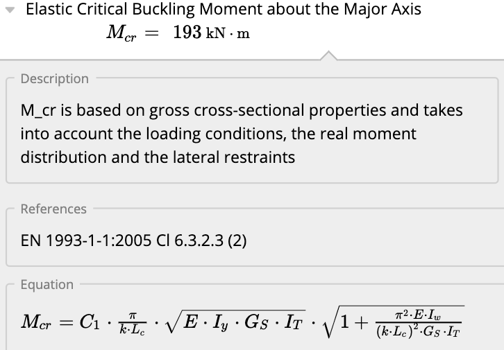
While the previous steps are all that is required to design our beam, it may be desirable to see more information about the beam. Calcs.com fully exposes all code calculations to see every step of the process employed to design the beam. For instance, we can go look at how the lateral-torsional buckling strength is calculated. Some calculations are hidden for clarity, however, they can be made visible by selecting "Detailed" mode. See [163-how-to-view-all-detailed-calculation-steps](/docs/running-calculations/checking-results/view-all-detailed-calculation-steps). For example, see the equation for the elastic critical buckling moment
A more in-depth look
While the previous steps are all that is required to design our beam, it may be desirable to see more information about the beam. Calcs.com fully exposes all code calculations to see every step of the process employed to design the beam. For instance, we can go look at how the lateral-torsional buckling strength is calculated. Some calculations are hidden for clarity, however, they can be made visible by selecting "Detailed" mode. See [163-how-to-view-all-detailed-calculation-steps](/docs/running-calculations/checking-results/view-all-detailed-calculation-steps). For example, see the equation for the elastic critical buckling moment
 This concludes our short tutorial on designing a steel beam per EN1993-1-1:2015 with Calcs.com.
## Available presets
Each preset opens the calculator with a typical setup already entered.
| Preset | Open in Calcs.com |
| ------------------------------------------------------------- | ---------------------------------------------------------------------------------------------- |
| Generic Beam | [Run with preset](https://app.calcs.com/new/sheet/EUsteelComplexBeam?presetCode=genericBeam) |
| Rafter | [Run with preset](https://app.calcs.com/new/sheet/EUsteelComplexBeam?presetCode=rafter) |
| Roof Bearer | [Run with preset](https://app.calcs.com/new/sheet/EUsteelComplexBeam?presetCode=roofBearer) |
| Underpurlin | [Run with preset](https://app.calcs.com/new/sheet/EUsteelComplexBeam?presetCode=underpurlin) |
| Strutting / Counter-Strutting Beam | [Run with preset](https://app.calcs.com/new/sheet/EUsteelComplexBeam?presetCode=struttingBeam) |
| Verandah Beam | [Run with preset](https://app.calcs.com/new/sheet/EUsteelComplexBeam?presetCode=verandahBeam) |
| Hanging Beam | [Run with preset](https://app.calcs.com/new/sheet/EUsteelComplexBeam?presetCode=hangingBeam) |
| Ceiling Joist | [Run with preset](https://app.calcs.com/new/sheet/EUsteelComplexBeam?presetCode=ceilingJoist) |
| Roof Lintel | [Run with preset](https://app.calcs.com/new/sheet/EUsteelComplexBeam?presetCode=roofLintel) |
| Floor Joist | [Run with preset](https://app.calcs.com/new/sheet/EUsteelComplexBeam?presetCode=floorJoist) |
| Floor Bearer | [Run with preset](https://app.calcs.com/new/sheet/EUsteelComplexBeam?presetCode=floorBearer) |
| Floor Lintel | [Run with preset](https://app.calcs.com/new/sheet/EUsteelComplexBeam?presetCode=floorLintel) |
## Common questions
The calculator designs steel beams to EN 1993-1-1:2005 (Eurocode 3), with shear buckling checks per EN 1993-1-5:2006. Load combinations follow EN 1990:2002. Three serviceability deflection combinations are checked, characteristic (irreversible), frequent (reversible), and quasi-permanent (long-term). Partial factors can be adjusted for the relevant National Annex.
Key inputs include the steel section (selected from the built-in database of European hot-rolled and hollow sections), steel grade, beam span and support layout, loads by type (permanent G, variable Q, wind W, snow S), lateral restraint spacing for LTB, transverse stiffener spacing for shear buckling, and deflection limit ratios per span.
The calculator checks cross-section class (EN 1993-1-1:2005 Cl 5.5.2), section bending capacity (Cl 6.2.5), design shear resistance (Cl 6.2.6), shear buckling of the web (EN 1993-1-5:2006 Cl 5.5), combined bending and shear for shear buckling (Cl 7.1), lateral torsional buckling (Cl 6.3.2.1), and three EN 1990:2002 deflection limit states.
Lateral torsional buckling resistance is computed per EN 1993-1-1:2005 Cl 6.3.2.1 using the general or simplified method. The critical elastic moment M\_cr is computed from the unbraced length between lateral restraints. The reduction factor chi\_LT is applied to the full plastic or elastic section moment resistance depending on section class. The calculator shows the governing lambda\_LT and chi\_LT.
For webs where the slenderness hw/tw exceeds 72 epsilon/eta, shear buckling is checked per EN 1993-1-5:2006 Cl 5.5. The contribution method separates flange and web contributions to shear resistance. Where transverse stiffeners are present, they are accounted for in the web buckling coefficient k\_tau. Combined bending and shear buckling interaction is then checked per EN 1993-1-1:2005 Cl 7.1.
Yes, beam reactions link directly to connected column and footing calculations in the same project. When you change a span, load, or section, all downstream calculations update automatically, no manual re-entry of reactions required.
## Next steps
Design steel columns and studs to EN 1993-1-1:2005 (Eurocode 3). Checks axial compression, biaxial bending, interaction, LTB and deflection.
Design timber columns and studs to EN 1995-1-1:2004 (Eurocode 5), with load linking and a database of European and UK timber sections.
Design simple and continuous timber beams to EN 1995-1-1:2004+A1:2008 (Eurocode 5) with unlimited supports and loads.
A comprehensive guide to designing a steel building using Eurocodes, including joists, columns and trusses with step-by-step examples
This concludes our short tutorial on designing a steel beam per EN1993-1-1:2015 with Calcs.com.
## Available presets
Each preset opens the calculator with a typical setup already entered.
| Preset | Open in Calcs.com |
| ------------------------------------------------------------- | ---------------------------------------------------------------------------------------------- |
| Generic Beam | [Run with preset](https://app.calcs.com/new/sheet/EUsteelComplexBeam?presetCode=genericBeam) |
| Rafter | [Run with preset](https://app.calcs.com/new/sheet/EUsteelComplexBeam?presetCode=rafter) |
| Roof Bearer | [Run with preset](https://app.calcs.com/new/sheet/EUsteelComplexBeam?presetCode=roofBearer) |
| Underpurlin | [Run with preset](https://app.calcs.com/new/sheet/EUsteelComplexBeam?presetCode=underpurlin) |
| Strutting / Counter-Strutting Beam | [Run with preset](https://app.calcs.com/new/sheet/EUsteelComplexBeam?presetCode=struttingBeam) |
| Verandah Beam | [Run with preset](https://app.calcs.com/new/sheet/EUsteelComplexBeam?presetCode=verandahBeam) |
| Hanging Beam | [Run with preset](https://app.calcs.com/new/sheet/EUsteelComplexBeam?presetCode=hangingBeam) |
| Ceiling Joist | [Run with preset](https://app.calcs.com/new/sheet/EUsteelComplexBeam?presetCode=ceilingJoist) |
| Roof Lintel | [Run with preset](https://app.calcs.com/new/sheet/EUsteelComplexBeam?presetCode=roofLintel) |
| Floor Joist | [Run with preset](https://app.calcs.com/new/sheet/EUsteelComplexBeam?presetCode=floorJoist) |
| Floor Bearer | [Run with preset](https://app.calcs.com/new/sheet/EUsteelComplexBeam?presetCode=floorBearer) |
| Floor Lintel | [Run with preset](https://app.calcs.com/new/sheet/EUsteelComplexBeam?presetCode=floorLintel) |
## Common questions
The calculator designs steel beams to EN 1993-1-1:2005 (Eurocode 3), with shear buckling checks per EN 1993-1-5:2006. Load combinations follow EN 1990:2002. Three serviceability deflection combinations are checked, characteristic (irreversible), frequent (reversible), and quasi-permanent (long-term). Partial factors can be adjusted for the relevant National Annex.
Key inputs include the steel section (selected from the built-in database of European hot-rolled and hollow sections), steel grade, beam span and support layout, loads by type (permanent G, variable Q, wind W, snow S), lateral restraint spacing for LTB, transverse stiffener spacing for shear buckling, and deflection limit ratios per span.
The calculator checks cross-section class (EN 1993-1-1:2005 Cl 5.5.2), section bending capacity (Cl 6.2.5), design shear resistance (Cl 6.2.6), shear buckling of the web (EN 1993-1-5:2006 Cl 5.5), combined bending and shear for shear buckling (Cl 7.1), lateral torsional buckling (Cl 6.3.2.1), and three EN 1990:2002 deflection limit states.
Lateral torsional buckling resistance is computed per EN 1993-1-1:2005 Cl 6.3.2.1 using the general or simplified method. The critical elastic moment M\_cr is computed from the unbraced length between lateral restraints. The reduction factor chi\_LT is applied to the full plastic or elastic section moment resistance depending on section class. The calculator shows the governing lambda\_LT and chi\_LT.
For webs where the slenderness hw/tw exceeds 72 epsilon/eta, shear buckling is checked per EN 1993-1-5:2006 Cl 5.5. The contribution method separates flange and web contributions to shear resistance. Where transverse stiffeners are present, they are accounted for in the web buckling coefficient k\_tau. Combined bending and shear buckling interaction is then checked per EN 1993-1-1:2005 Cl 7.1.
Yes, beam reactions link directly to connected column and footing calculations in the same project. When you change a span, load, or section, all downstream calculations update automatically, no manual re-entry of reactions required.
## Next steps
Design steel columns and studs to EN 1993-1-1:2005 (Eurocode 3). Checks axial compression, biaxial bending, interaction, LTB and deflection.
Design timber columns and studs to EN 1995-1-1:2004 (Eurocode 5), with load linking and a database of European and UK timber sections.
Design simple and continuous timber beams to EN 1995-1-1:2004+A1:2008 (Eurocode 5) with unlimited supports and loads.
A comprehensive guide to designing a steel building using Eurocodes, including joists, columns and trusses with step-by-step examples
