> ## Documentation Index
> Fetch the complete documentation index at: https://calcs.com/docs/llms.txt
> Use this file to discover all available pages before exploring further.
# Design a Steel Column to EN 1993 (Eurocode 3)
> Design steel columns and studs to EN 1993-1-1:2005 (Eurocode 3). Checks axial compression, biaxial bending, interaction, LTB and deflection.
EuropeEN 1993-1-5:2006SCI Publication P360 (2011)
Column loads link from beam reactions above to footing calculations below automatically. Design steel columns and studs to Eurocode 3 with multiple end fixity conditions, checks cover axial compression, bending about both axes, combined bending and axial interaction, lateral torsional buckling, and three deflection limits.
#### Background
The EU steel column calculator can be used to calculate both the demands as well as the resistance of a straight column.\
The analysis capabilities include:
* Point Axial and lateral forces
* Point moments in the major and minor axis (excluding torsion)
* Line Loads (including linearly varying)
* Distributed Loads (including varying tributary width). For details on tributary widths, refer article [170-what-is-tributary-width](/docs/running-calculations/setting-up-a-calculation/loads/what-is-tributary-width)
The design capabilities include:
* Cross-section classification (Class 4 section design not available)
* ULS: Axial compression and tension resistance (EN 1993-1-1:2005 Cl 6.2.3 & 4)
* ULS: Reduced bi-axial moment resistance taking into account axial and shear forces (EN 1993-1-1:2005 Cl 6.2.5)
* ULS: Shear resistance (EN 1993-1-1:2005 Cl 6.2.6)
* ULS: Lateral torsional buckling resistance of uniform member in bending (EN 1993-1-1:2005 Cl 6.3.2)
* ULS: Buckling resistance in combined bending and axial compression (EN 1993-1-1:2005 Cl 6.3.3)
* ULS: Flexural buckling resistance in axial compression (EN 1993-1-1:2005 Cl 6.3.1)
* ULS: Shear web buckling resistance of uniform member (EN 1993-1-5:2006 Cl 5.1-5.5) including transverse stiffeners.
* SLS: Deflection analysis
* Penetrations or fastener holes (checks if they may be ignored)
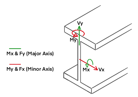
Coordinate System:
Within Calcs.com, the z-z axis is taken axis as the longitudinal axis of a member and the x–x and y–y axes to denote the respective major and minor axes. In the Eurocode suite the longitudinal axis, in contrast, is the x–x axis and the y–y and z–z axes are the respective major and minor axes. The Calcs.com terms are used below.
 #### Tutorial
In this worked design example, we will go through the design process of a single-span simply supported steel column with axial and lateral point loads. The span is 7.2m long and the column is laterally restrained at the location of concentrated loads.
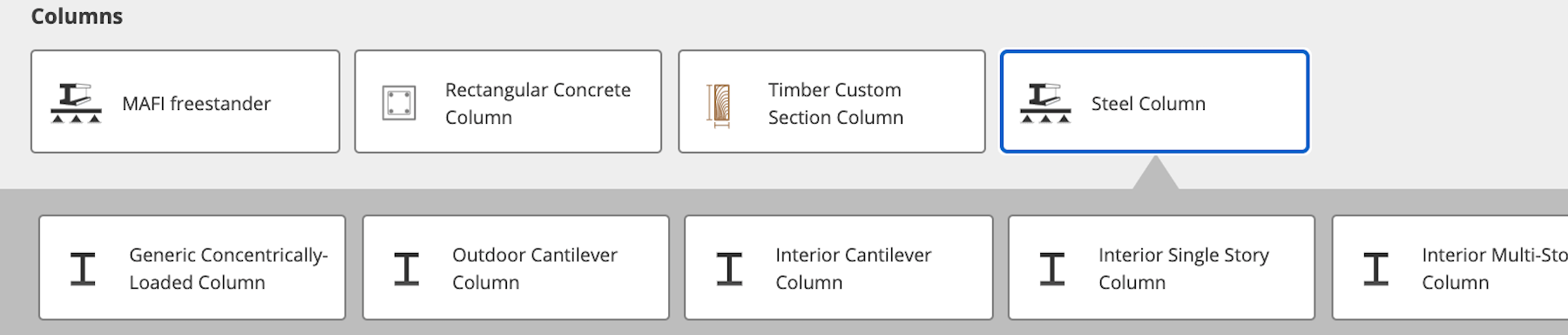
The calculation (including for biaxial moment) may be accomplished in any Steel Column Calculator shown below. When choosing concentric-loading only, options for bending moment/shear checks will only be shown once lateral forces/eccentricities are applied. We will choose an *"Interior Single Story Column"* as the most similar to our final column arrangement.
#### Tutorial
In this worked design example, we will go through the design process of a single-span simply supported steel column with axial and lateral point loads. The span is 7.2m long and the column is laterally restrained at the location of concentrated loads.
The calculation (including for biaxial moment) may be accomplished in any Steel Column Calculator shown below. When choosing concentric-loading only, options for bending moment/shear checks will only be shown once lateral forces/eccentricities are applied. We will choose an *"Interior Single Story Column"* as the most similar to our final column arrangement.
 ## Method & scope
| Property | Detail |
| ---------------- | ------------------------------------------------------------------------------------------------------------------------------------------------------------------------------------------------------------------------------------------------------------------------------------------------------------------------------------------------------------------------------ |
| Design standards | EN 1993-1-1:2005 (Eurocode 3), EN 1993-1-5:2006, SCI Publication P360 (2011), JRC (2007) Commentary and Worked Examples to EN 1993-1-5 |
| Regions | Europe |
| Presets | Generic Concentrically-Loaded Column, Outdoor Cantilever Column, Interior Cantilever Column, Interior Single Story Column, Interior Multi-Story Column, Perimeter Multi-Story Column, Corner Multi-Story Column |
| What it checks | Structural model and load combinations, Cross-section classification (EN 1993-1-1:2005 Cl 5.5.2), Cross-section resistance, Flexural buckling resistance (EN 1993-1-1:2005 Cl 6.3.1), Lateral torsional buckling (EN 1993-1-1:2005 Cl 6.3.2.1), Combined bending and axial compression, member buckling (EN 1993-1-1:2005 Cl 6.3.3), Deflection checks (EN 1990:2002 Cl 6.5.3) |
#### Informational and National Annexes
Eurocode allows location-specific factors and/or calculation methods to be utilized. These are usually stipulated within National Annexes to EN1993-1-1:2005. The following customizations are provided within Calcs.com:
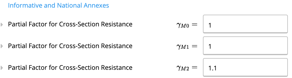
* *Partial Factors for cross-section resistance -* The recommended values within EN1993-1-1:2005 Cl 6.1(1) are provided by default, however, modified values should be used specifically to the relevant National Annex. As we are designing this example in accordance with the UK annex, we will amend the Gamma\_M2 value to 1.1 from the default 1.25.
* *
## Method & scope
| Property | Detail |
| ---------------- | ------------------------------------------------------------------------------------------------------------------------------------------------------------------------------------------------------------------------------------------------------------------------------------------------------------------------------------------------------------------------------ |
| Design standards | EN 1993-1-1:2005 (Eurocode 3), EN 1993-1-5:2006, SCI Publication P360 (2011), JRC (2007) Commentary and Worked Examples to EN 1993-1-5 |
| Regions | Europe |
| Presets | Generic Concentrically-Loaded Column, Outdoor Cantilever Column, Interior Cantilever Column, Interior Single Story Column, Interior Multi-Story Column, Perimeter Multi-Story Column, Corner Multi-Story Column |
| What it checks | Structural model and load combinations, Cross-section classification (EN 1993-1-1:2005 Cl 5.5.2), Cross-section resistance, Flexural buckling resistance (EN 1993-1-1:2005 Cl 6.3.1), Lateral torsional buckling (EN 1993-1-1:2005 Cl 6.3.2.1), Combined bending and axial compression, member buckling (EN 1993-1-1:2005 Cl 6.3.3), Deflection checks (EN 1990:2002 Cl 6.5.3) |
#### Informational and National Annexes
Eurocode allows location-specific factors and/or calculation methods to be utilized. These are usually stipulated within National Annexes to EN1993-1-1:2005. The following customizations are provided within Calcs.com:
* *Partial Factors for cross-section resistance -* The recommended values within EN1993-1-1:2005 Cl 6.1(1) are provided by default, however, modified values should be used specifically to the relevant National Annex. As we are designing this example in accordance with the UK annex, we will amend the Gamma\_M2 value to 1.1 from the default 1.25.
* * *
* *Interaction Factors for compression and bending buckling resistance* - 2 methods are provided within the informational annexes. The engineer should consider both the national annex requirements as well as the validity of each method for the type of sections they are designing. Annex A has been chosen, which is allowed for doubly-symmetric sections in NA2.21 of NA+A1:2014 to BS EN 1993-1-1:2005.
*
*
* *Interaction Factors for compression and bending buckling resistance* - 2 methods are provided within the informational annexes. The engineer should consider both the national annex requirements as well as the validity of each method for the type of sections they are designing. Annex A has been chosen, which is allowed for doubly-symmetric sections in NA2.21 of NA+A1:2014 to BS EN 1993-1-1:2005.
*  *Deflection Limits -* These vary based on the type of the structure, whether it is a column or beam, as well as national annex preferences. Extension limits are not provided, however where differential deflections of multiple columns may induce secondary impacts, a separate check should be conducted. In this example, we may use NA+A1:2014 to BS EN1993-1-1:2005 Table NA.3 (In each story of a building with more than one story -> L/300). These may be adjusted within Project Defaults which apply to all designs within the project, however in this case we will amend them specifically for this column.
 #### Assumptions and Limitations
Calcs.com fully exposes all code calculations to see every step of the process employed to design the column. Therefore, the engineer should have confidence that they can look at every calculation and conditional statement that is used to derive the final result. A summary of assumptions is provided below:
* Columns are computed by a chosen limit state and load combination. It is up to the user to choose limit states to determine the worst loading case combination. These may be viewed and/or modified in Project Defaults.
* Hollow sections are analyzed as cold-formed (more conservative than hot-finished) for the purposes of buckling checks)
* Flexural torsional buckling (Cl 6.3.1.4 EN1993.1.1:2005) is not checked as the database hot-rolled sections and hollow sections will always have more critical flexural buckling limits.
* Supports are equally applied about both axes (i.e. fixed in bending about major and minor axes)
#### References
The worked example above is based on *"* *Example 6.9, Gardner, Nethercot, 2011, Designers Guide to EN-1993-1-1-Eurocode-3"*
#### See the exact clause
Every check in this calculator links back to its governing clause in EN 1993. Open the **Formula Reference** panel on any result and select the clause reference to read it. See [Viewing Clauses from Inside a Calculator](/docs/running-calculations/standards-and-codes/viewing-clauses-from-inside-calculator).
#### Calculation method
##### Structural model and load combinations
The calculator models the steel column as a member under combined axial force and biaxial bending. Loads are entered by type, permanent (G), variable (Q), wind (W), and EN 1990:2002 governing ULS combinations are generated automatically. Bending moments can be entered directly or linked from beam calculations above. Three serviceability combinations generate deflection checks.
##### Cross-section classification (EN 1993-1-1:2005 Cl 5.5.2)
Cross-section class (Class 1 through 4) is determined independently for major-axis bending, minor-axis bending, and axial compression based on element slenderness and epsilon = sqrt(235/fy). The governing class controls which section moduli (plastic, elastic, or effective) are used in the resistance calculations.
##### Cross-section resistance
**Axial compression (Cl 6.2.4):** N\_c,Rd = A × fy / gamma\_M0 for Class 1-3, or A\_eff × fy / gamma\_M0 for Class 4.
**Bending (Cl 6.2.5):** M\_c,Rd uses W\_pl for Class 1-2, W\_el for Class 3, and W\_eff for Class 4, independently for both axes.
**Shear (Cl 6.2.6):** V\_Rd is computed from the shear area A\_v and yield strength fy for each axis.
**Biaxial bending criterion:** For combined major and minor axis bending without axial force, the biaxial criterion limits the sum of moment utilization ratios.
**Simplified biaxial bending and axial criterion (Cl 6.2.9.2):** For combined axial and biaxial bending, the simplified linear interaction is checked alongside the more precise longitudinal stress criterion at the extreme fibers.
##### Flexural buckling resistance (EN 1993-1-1:2005 Cl 6.3.1)
Flexural buckling resistance N\_b,Rd is computed for each axis using the reduction factor chi, derived from the relative slenderness lambda = sqrt(A×fy/N\_cr). N\_cr is the Euler critical load based on the effective buckling length. The imperfection factor alpha depends on the section type and axis (buckling curves a0, a, b, c, d per Table 6.2).
**buckling utilization** = N\_Ed / N\_b,Rd ≤ 1.0
##### Lateral torsional buckling (EN 1993-1-1:2005 Cl 6.3.2.1)
When the compression flange is not fully laterally restrained, LTB resistance M\_b,Rd is computed using chi\_LT from the relative slenderness lambda\_LT derived from M\_cr. The critical moment M\_cr accounts for unbraced length, end conditions, and section warping and torsional properties.
##### Combined bending and axial compression, member buckling (EN 1993-1-1:2005 Cl 6.3.3)
The combined buckling interaction is checked through two equations using interaction factors k\_yy, k\_yz, k\_zy, k\_zz:
* N\_Ed/(chi\_y × N\_Rk/gamma\_M1) + k\_yy × M\_y,Ed/M\_b,Rd + k\_yz × M\_z,Ed/M\_Rk × gamma\_M1 ≤ 1.0
* N\_Ed/(chi\_z × N\_Rk/gamma\_M1) + k\_zy × M\_y,Ed/M\_b,Rd + k\_zz × M\_z,Ed/M\_Rk × gamma\_M1 ≤ 1.0
The governing equation and utilization ratio are reported. Interaction factors are derived from the moment distribution (C\_m factors) and relative slendernesses.
##### Deflection checks (EN 1990:2002 Cl 6.5.3)
Characteristic, frequent, and quasi-permanent deflections are checked against user-defined span-ratio limits and optional absolute limits in mm.
##### Load linking
The column's base reaction is exported as a linked output to connected footing calculations. Axial load at the column top can be linked from beam reactions above, completing the full load path from beam to column to footing automatically.
## How to use it
First, we enter the key properties of our column:
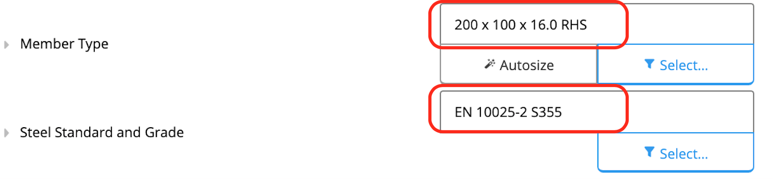
* *Member Type & Steel Grade* - Clicking "Select" will open a list of all properties and allow you to select an initial size and grade. Refer to related article [Quickly finding the best section with the member selector](/docs/running-calculations/member-selector/index)
#### Assumptions and Limitations
Calcs.com fully exposes all code calculations to see every step of the process employed to design the column. Therefore, the engineer should have confidence that they can look at every calculation and conditional statement that is used to derive the final result. A summary of assumptions is provided below:
* Columns are computed by a chosen limit state and load combination. It is up to the user to choose limit states to determine the worst loading case combination. These may be viewed and/or modified in Project Defaults.
* Hollow sections are analyzed as cold-formed (more conservative than hot-finished) for the purposes of buckling checks)
* Flexural torsional buckling (Cl 6.3.1.4 EN1993.1.1:2005) is not checked as the database hot-rolled sections and hollow sections will always have more critical flexural buckling limits.
* Supports are equally applied about both axes (i.e. fixed in bending about major and minor axes)
#### References
The worked example above is based on *"* *Example 6.9, Gardner, Nethercot, 2011, Designers Guide to EN-1993-1-1-Eurocode-3"*
#### See the exact clause
Every check in this calculator links back to its governing clause in EN 1993. Open the **Formula Reference** panel on any result and select the clause reference to read it. See [Viewing Clauses from Inside a Calculator](/docs/running-calculations/standards-and-codes/viewing-clauses-from-inside-calculator).
#### Calculation method
##### Structural model and load combinations
The calculator models the steel column as a member under combined axial force and biaxial bending. Loads are entered by type, permanent (G), variable (Q), wind (W), and EN 1990:2002 governing ULS combinations are generated automatically. Bending moments can be entered directly or linked from beam calculations above. Three serviceability combinations generate deflection checks.
##### Cross-section classification (EN 1993-1-1:2005 Cl 5.5.2)
Cross-section class (Class 1 through 4) is determined independently for major-axis bending, minor-axis bending, and axial compression based on element slenderness and epsilon = sqrt(235/fy). The governing class controls which section moduli (plastic, elastic, or effective) are used in the resistance calculations.
##### Cross-section resistance
**Axial compression (Cl 6.2.4):** N\_c,Rd = A × fy / gamma\_M0 for Class 1-3, or A\_eff × fy / gamma\_M0 for Class 4.
**Bending (Cl 6.2.5):** M\_c,Rd uses W\_pl for Class 1-2, W\_el for Class 3, and W\_eff for Class 4, independently for both axes.
**Shear (Cl 6.2.6):** V\_Rd is computed from the shear area A\_v and yield strength fy for each axis.
**Biaxial bending criterion:** For combined major and minor axis bending without axial force, the biaxial criterion limits the sum of moment utilization ratios.
**Simplified biaxial bending and axial criterion (Cl 6.2.9.2):** For combined axial and biaxial bending, the simplified linear interaction is checked alongside the more precise longitudinal stress criterion at the extreme fibers.
##### Flexural buckling resistance (EN 1993-1-1:2005 Cl 6.3.1)
Flexural buckling resistance N\_b,Rd is computed for each axis using the reduction factor chi, derived from the relative slenderness lambda = sqrt(A×fy/N\_cr). N\_cr is the Euler critical load based on the effective buckling length. The imperfection factor alpha depends on the section type and axis (buckling curves a0, a, b, c, d per Table 6.2).
**buckling utilization** = N\_Ed / N\_b,Rd ≤ 1.0
##### Lateral torsional buckling (EN 1993-1-1:2005 Cl 6.3.2.1)
When the compression flange is not fully laterally restrained, LTB resistance M\_b,Rd is computed using chi\_LT from the relative slenderness lambda\_LT derived from M\_cr. The critical moment M\_cr accounts for unbraced length, end conditions, and section warping and torsional properties.
##### Combined bending and axial compression, member buckling (EN 1993-1-1:2005 Cl 6.3.3)
The combined buckling interaction is checked through two equations using interaction factors k\_yy, k\_yz, k\_zy, k\_zz:
* N\_Ed/(chi\_y × N\_Rk/gamma\_M1) + k\_yy × M\_y,Ed/M\_b,Rd + k\_yz × M\_z,Ed/M\_Rk × gamma\_M1 ≤ 1.0
* N\_Ed/(chi\_z × N\_Rk/gamma\_M1) + k\_zy × M\_y,Ed/M\_b,Rd + k\_zz × M\_z,Ed/M\_Rk × gamma\_M1 ≤ 1.0
The governing equation and utilization ratio are reported. Interaction factors are derived from the moment distribution (C\_m factors) and relative slendernesses.
##### Deflection checks (EN 1990:2002 Cl 6.5.3)
Characteristic, frequent, and quasi-permanent deflections are checked against user-defined span-ratio limits and optional absolute limits in mm.
##### Load linking
The column's base reaction is exported as a linked output to connected footing calculations. Axial load at the column top can be linked from beam reactions above, completing the full load path from beam to column to footing automatically.
## How to use it
First, we enter the key properties of our column:
* *Member Type & Steel Grade* - Clicking "Select" will open a list of all properties and allow you to select an initial size and grade. Refer to related article [Quickly finding the best section with the member selector](/docs/running-calculations/member-selector/index)
 * *Total Column Length* - The length between the start and end of the column, irrespective of the support conditions.
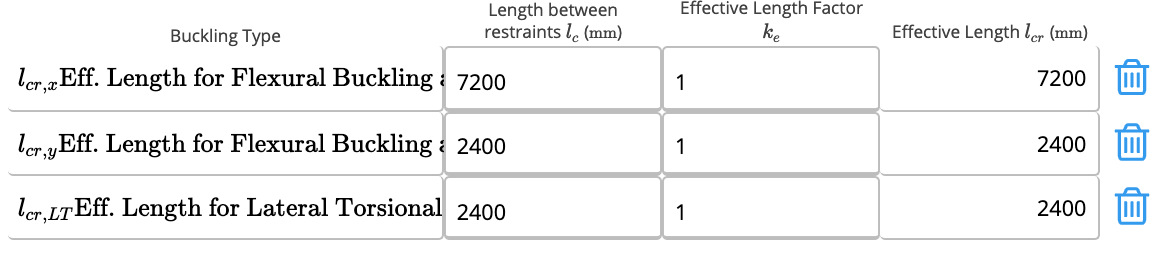
* *Length between lateral restraints* - Let’s assume that the column is braced at concentrated load locations, so the length between lateral restraints is equal to a third of the total column span of 7.2m. Note that effective length is defined about both axes, as well as separately for lateral torsional buckling. Where effective lengths are the same in both axes for flexural buckling, the section will always buckle in the minor axis.
*
* *Total Column Length* - The length between the start and end of the column, irrespective of the support conditions.
* *Length between lateral restraints* - Let’s assume that the column is braced at concentrated load locations, so the length between lateral restraints is equal to a third of the total column span of 7.2m. Note that effective length is defined about both axes, as well as separately for lateral torsional buckling. Where effective lengths are the same in both axes for flexural buckling, the section will always buckle in the minor axis.
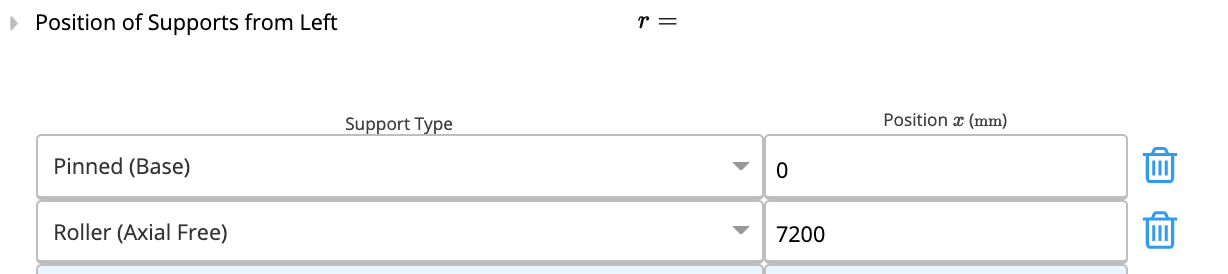
*  * *Position of Supports from Left* - The support conditions may be at any position along the column. A cantilever can be created on either end by moving the support condition away from "0" or the "Total Column Length"
*
* *Position of Supports from Left* - The support conditions may be at any position along the column. A cantilever can be created on either end by moving the support condition away from "0" or the "Total Column Length"
*  NOTE: The column calculator can accommodate any combination of axial and bending moment about either or both axes. E.g. Calculations for bending moment/shear will only be available where lateral loads/eccentricities are applied. Any calculator template
* *Axial force* - This may be applied as a point load at any location along the column. The self-weight of the member may additionally be added via the toggle. Axial Loads applied in either axes are combined together. This enables linking vertical loads from beams coming in from both axes.
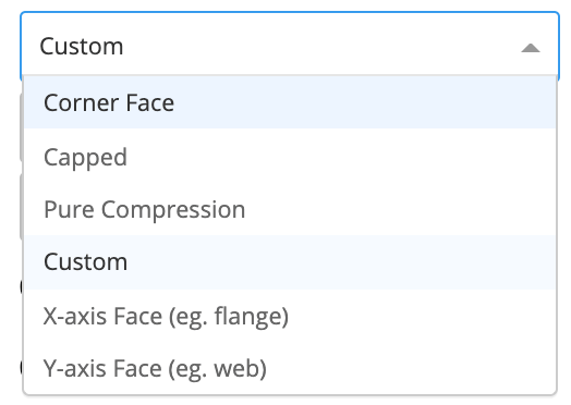
* *Axial Eccentricity* - Axial Eccentricity may be applied in either x- or y- directions. This can be set as a custom option or one of the default eccentricities may be set as listed below. It is important to familiarise yourself with the logic used for each option, which may be obtained by expanding the explanatory notes for the *"Default Eccentricity for Bending about ..."* as shown in the figure below.
*
NOTE: The column calculator can accommodate any combination of axial and bending moment about either or both axes. E.g. Calculations for bending moment/shear will only be available where lateral loads/eccentricities are applied. Any calculator template
* *Axial force* - This may be applied as a point load at any location along the column. The self-weight of the member may additionally be added via the toggle. Axial Loads applied in either axes are combined together. This enables linking vertical loads from beams coming in from both axes.
* *Axial Eccentricity* - Axial Eccentricity may be applied in either x- or y- directions. This can be set as a custom option or one of the default eccentricities may be set as listed below. It is important to familiarise yourself with the logic used for each option, which may be obtained by expanding the explanatory notes for the *"Default Eccentricity for Bending about ..."* as shown in the figure below.
* 
 *Load Direction -* Where all the loads are applied in one direction (as below) the sign of lateral loads is not important as all checks are conducted with the absolute moments for symmetric sections about the major
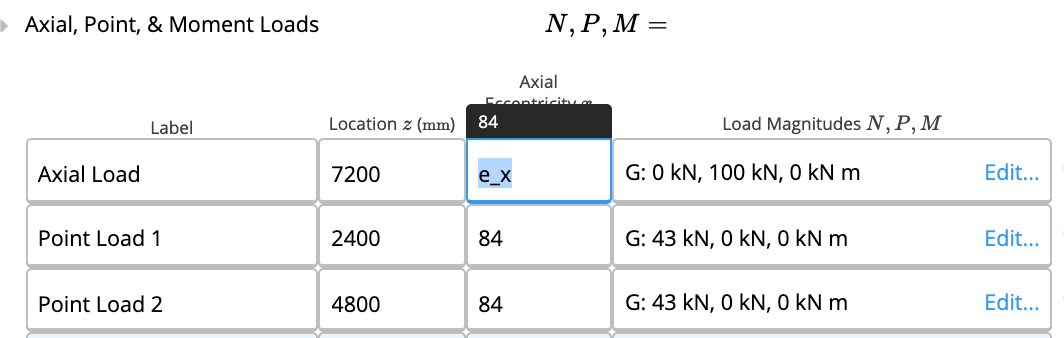
* *Lateral Point Loads -* We apply the loads at the 1/3 and 2/3 of the column length (2400mm and 4800mm). Note how the *"Capped"* axial eccentricity value is automatically inserted for every load created. This may be overridden on a load by load basis where required.
*
*Load Direction -* Where all the loads are applied in one direction (as below) the sign of lateral loads is not important as all checks are conducted with the absolute moments for symmetric sections about the major
* *Lateral Point Loads -* We apply the loads at the 1/3 and 2/3 of the column length (2400mm and 4800mm). Note how the *"Capped"* axial eccentricity value is automatically inserted for every load created. This may be overridden on a load by load basis where required.
* 
 We can now verify that our loads are all properly placed:
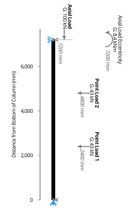 \
Note that the loads shown here are, by default, unfactored. For the factored combinations, you can visualize the applied loads on the right summary column, and choose the combination. The load combination can easily be changed with the dropdown above the graphics.
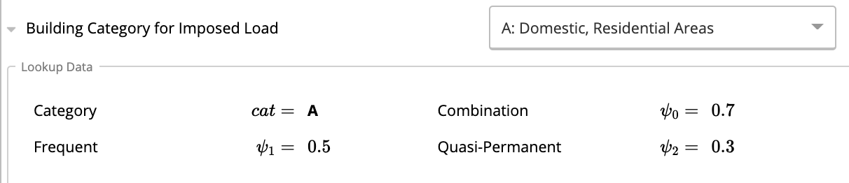
* *Imposed Load factors -* based on EN 1990:2002, Table A1.1 are chosen based on the category selection shown below. These populate the "Imposed Load Factors" to be used in the remainder of the calculation.
\
Note that the loads shown here are, by default, unfactored. For the factored combinations, you can visualize the applied loads on the right summary column, and choose the combination. The load combination can easily be changed with the dropdown above the graphics.
* *Imposed Load factors -* based on EN 1990:2002, Table A1.1 are chosen based on the category selection shown below. These populate the "Imposed Load Factors" to be used in the remainder of the calculation.
 * *Snow Location Category -* may be accessed in the *"Project Defaults"* tab on the sidebar.
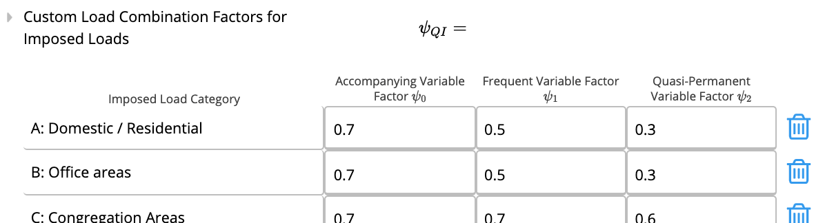
* *Custom load factors -* these may be amended in *"Project Defaults"* tab on the sidebar. Note this will affect load factors for all calculations in your current project. Go to *"Load Combinations"* section and change the *"Load Combination Factors"* to custom. This opens a range of options for *"Imposed"* load factors as well as *"Environmental"* factors:
* *Snow Location Category -* may be accessed in the *"Project Defaults"* tab on the sidebar.
* *Custom load factors -* these may be amended in *"Project Defaults"* tab on the sidebar. Note this will affect load factors for all calculations in your current project. Go to *"Load Combinations"* section and change the *"Load Combination Factors"* to custom. This opens a range of options for *"Imposed"* load factors as well as *"Environmental"* factors:

 At this point, we are ready to revise our member size. We go back to our "Member Type" tab and search for a utilization close to but not exceeding 100%. The currently selected member is governed by the L/300 deflection limit. This limit may be further discussed with the client/authorities if it is applicable for the building structure being designed. However, in this case, we will amend the section size to obtain a compliant deflection, utilizing also the handy filter bar.

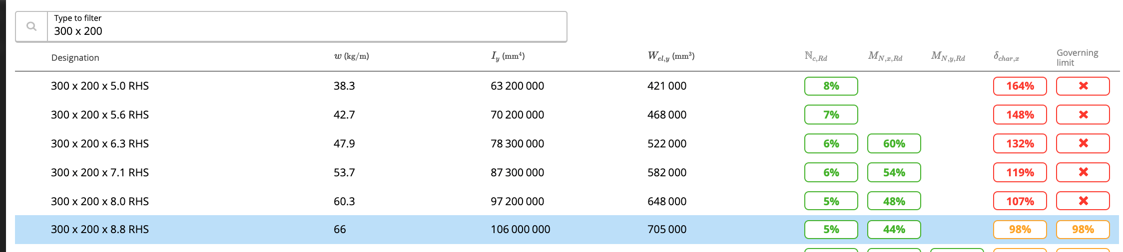 The four right-most columns indicate the utilization for five different checks – Axial Compression, Moment about major and minor axis, characteristic deflection, and Governing Limit. The governing column considers all checks and validation requirements within the entire calculation. A cross will signify that a particular requirement is not satisfied and no utilization may be calculated. Ideally, we want the minimal weight section that will satisfy all three modes. It is then a matter of scrolling to find the best cross-section. Looking through, we find a candidate – 300 x 200 x 8.8 RHS.
That’s it! We’ve now designed our column!
Once we’ve got our column design, we can quickly glance at relevant values to make sure everything corresponds to what we’d expect. On the right panel is the summary section, where we find things such as the critical moment demand and capacity, shear, moment and deflections. Where a calculation for lateral torsional buckling or web shear buckling was required based on Eurocode criteria, totals will also be shown.
The four right-most columns indicate the utilization for five different checks – Axial Compression, Moment about major and minor axis, characteristic deflection, and Governing Limit. The governing column considers all checks and validation requirements within the entire calculation. A cross will signify that a particular requirement is not satisfied and no utilization may be calculated. Ideally, we want the minimal weight section that will satisfy all three modes. It is then a matter of scrolling to find the best cross-section. Looking through, we find a candidate – 300 x 200 x 8.8 RHS.
That’s it! We’ve now designed our column!
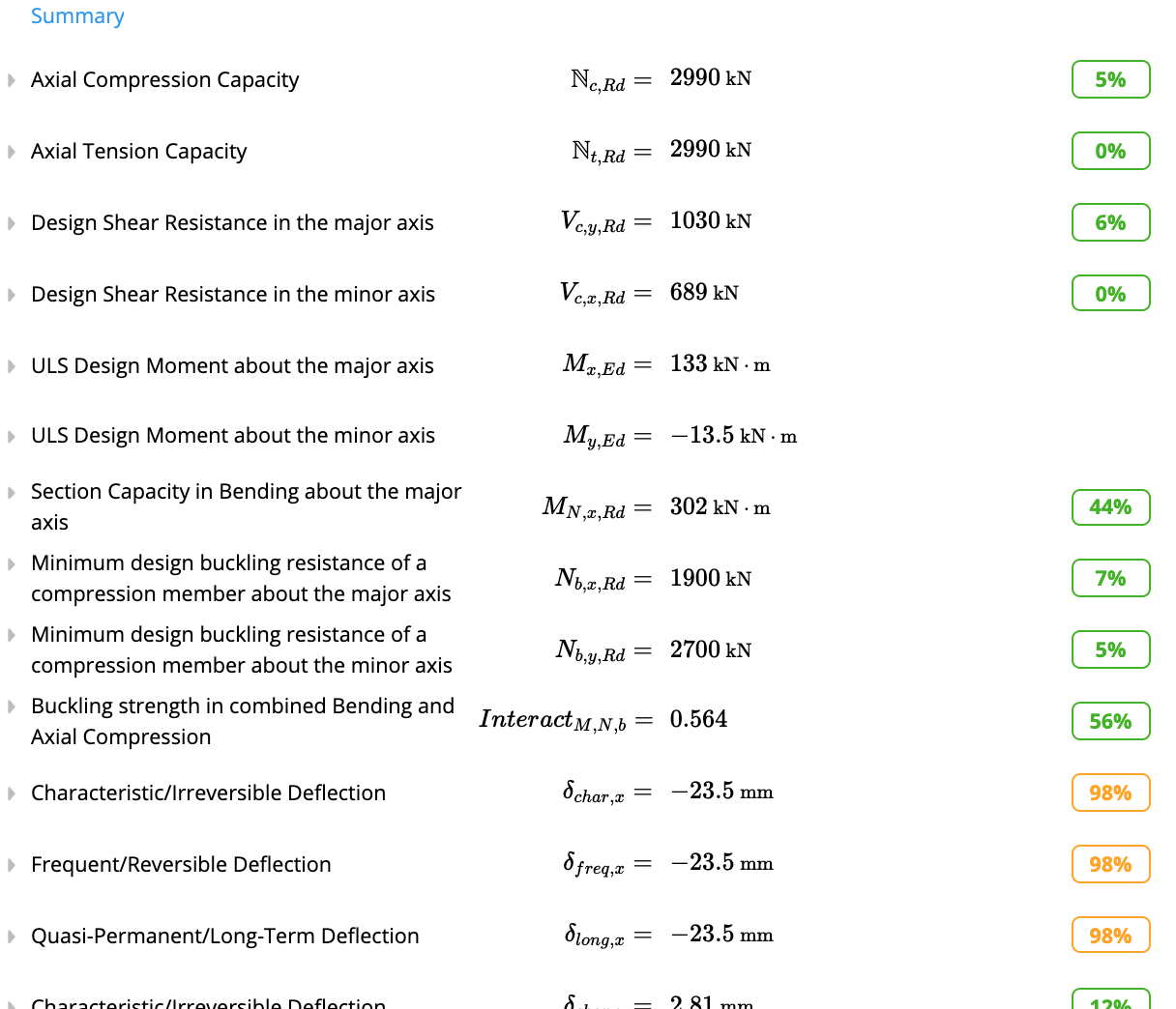
Once we’ve got our column design, we can quickly glance at relevant values to make sure everything corresponds to what we’d expect. On the right panel is the summary section, where we find things such as the critical moment demand and capacity, shear, moment and deflections. Where a calculation for lateral torsional buckling or web shear buckling was required based on Eurocode criteria, totals will also be shown.
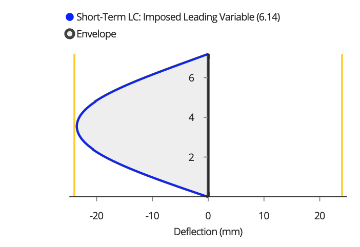
 We can also look at the shear, bending and deflection diagrams to make sure they correspond to what we anticipate.
For deflections, we need to switch the load case to reflect a serviceability load case – for here, it is simply “Service CHAR: Imposed Leading Variable”. We can scroll down the graph to see exact deflection values at different points. We clearly see that our deflection is limited by the 5mm hard limit we set. We may need to consider whether that hard limit is in fact required for this specific structure.
We can also look at the shear, bending and deflection diagrams to make sure they correspond to what we anticipate.
For deflections, we need to switch the load case to reflect a serviceability load case – for here, it is simply “Service CHAR: Imposed Leading Variable”. We can scroll down the graph to see exact deflection values at different points. We clearly see that our deflection is limited by the 5mm hard limit we set. We may need to consider whether that hard limit is in fact required for this specific structure.
 While the previous steps are all that is required to design our column, it may be desirable to improve the performance of the selected column by considering the following.
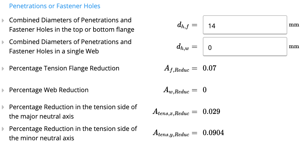
* *Penetrations or fastener holes* - For bending capacity checks, any reduction due to penetrations in a tension flange or tension part of the neutral axis may be ignored subject to certain limits being satisfied. A check is conducted below of a 14mm diameter hole for 12 diameter bolt holes.
*
While the previous steps are all that is required to design our column, it may be desirable to improve the performance of the selected column by considering the following.
* *Penetrations or fastener holes* - For bending capacity checks, any reduction due to penetrations in a tension flange or tension part of the neutral axis may be ignored subject to certain limits being satisfied. A check is conducted below of a 14mm diameter hole for 12 diameter bolt holes.
* 
 *Moment Distribution* - Several options are provided to amend the buckling capacity based on "actual" bending moment profiles. Calcs.com defaults all options to the worst-case bending moment profile (single curvature constant bending moment). C\_1 may be amended for lateral torsional buckling checks and the ratio of end moments for bending/axial interaction may be amended using the psi factors.
*
*Moment Distribution* - Several options are provided to amend the buckling capacity based on "actual" bending moment profiles. Calcs.com defaults all options to the worst-case bending moment profile (single curvature constant bending moment). C\_1 may be amended for lateral torsional buckling checks and the ratio of end moments for bending/axial interaction may be amended using the psi factors.
*  *
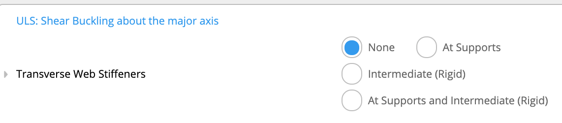
*  *Shear Buckling web stiffeners -* For large shear loads in thin-webbed sections. Transverse web stiffeners may increase the load at which the web will buckle.
*
*Shear Buckling web stiffeners -* For large shear loads in thin-webbed sections. Transverse web stiffeners may increase the load at which the web will buckle.
*  * *Buckling Interaction Factors* - Annex A and Annex B methods are implemented in Calcs.com, however higher capacities are usually obtained using Annex A, which may not be allowed for every section (non doubly symmetric
This concludes this tutorial on designing a steel column per EN1993-1-1:2015 with Calcs.com.
## Available presets
Each preset opens the calculator with a typical setup already entered.
| Preset | Open in Calcs.com |
| --------------------------------------------------------------- | ----------------------------------------------------------------------------------------------- |
| Generic Concentrically-Loaded Column | [Run with preset](https://app.calcs.com/new/sheet/EUsteelColumn?presetCode=genericColumn) |
| Outdoor Cantilever Column | [Run with preset](https://app.calcs.com/new/sheet/EUsteelColumn?presetCode=outdoorCantilever) |
| Interior Cantilever Column | [Run with preset](https://app.calcs.com/new/sheet/EUsteelColumn?presetCode=interiorCantilever) |
| Interior Single Story Column | [Run with preset](https://app.calcs.com/new/sheet/EUsteelColumn?presetCode=interiorStud) |
| Interior Multi-Story Column | [Run with preset](https://app.calcs.com/new/sheet/EUsteelColumn?presetCode=interiorMultiStory) |
| Perimeter Multi-Story Column | [Run with preset](https://app.calcs.com/new/sheet/EUsteelColumn?presetCode=perimeterMultiStory) |
| Corner Multi-Story Column | [Run with preset](https://app.calcs.com/new/sheet/EUsteelColumn?presetCode=cornerMultiStory) |
## Common questions
The calculator designs steel columns to EN 1993-1-1:2005 (Eurocode 3), with shear buckling per EN 1993-1-5:2006 where applicable. Load combinations follow EN 1990:2002. Partial factors can be adjusted per the relevant National Annex. Cross-section classes are determined for both axes, and buckling curves are selected based on section type and axis of buckling.
Key inputs include the steel section (from the built-in European section database), steel grade, column height, effective length factors for both major and minor axes, loads by type (permanent G, variable Q, wind W), bending moments about both axes, and deflection limit ratios. End fixity conditions (pinned, fixed, cantilever) can be set independently for each axis.
The calculator checks cross-section axial compression, axial tension, section bending capacity about both axes (EN 1993-1-1:2005 Cl 6.2.5), shear resistance about both axes (Cl 6.2.6), biaxial bending and the simplified biaxial bending-plus-axial criterion, longitudinal stress (Cl 6.2.9.2), buckling resistance about both axes, lateral torsional buckling (Cl 6.3.2.1), combined bending-and-axial-compression buckling (Cl 6.3.3), shear buckling, and three EN 1990:2002 deflection limits.
The combined buckling check follows EN 1993-1-1:2005 Cl 6.3.3 using interaction factors k\_yy, k\_zy, k\_yz, k\_zz from Annex A or B (method 1 or 2). These factors account for the ratio of end moments, moment gradient correction C\_m, and the relative slendernesses about each axis. The calculator applies both interaction equations and reports the governing utilization ratio.
Cross-section class is determined independently for major-axis bending, minor-axis bending, and axial compression. The most onerous classification governs for each check. For Class 1 and 2 sections, plastic resistances are used; Class 3 uses elastic section moduli; Class 4 uses effective cross-section properties accounting for local buckling of slender elements.
Yes, axial load at the column top can be linked from beam reactions above, and the column's base reaction links to connected footing calculations. The full load path, beam to column to footing, updates automatically whenever any upstream input changes.
## Next steps
Design steel beams to EN 1993-1-1:2005 (Eurocode 3) with unlimited spans and loads. Checks bending, LTB, shear, web buckling and deflection.
Design timber columns and studs to EN 1995-1-1:2004 (Eurocode 5), with load linking and a database of European and UK timber sections.
Design simple and continuous timber beams to EN 1995-1-1:2004+A1:2008 (Eurocode 5) with unlimited supports and loads.
A comprehensive guide to designing a steel building using Eurocodes, including joists, columns and trusses with step-by-step examples
* *Buckling Interaction Factors* - Annex A and Annex B methods are implemented in Calcs.com, however higher capacities are usually obtained using Annex A, which may not be allowed for every section (non doubly symmetric
This concludes this tutorial on designing a steel column per EN1993-1-1:2015 with Calcs.com.
## Available presets
Each preset opens the calculator with a typical setup already entered.
| Preset | Open in Calcs.com |
| --------------------------------------------------------------- | ----------------------------------------------------------------------------------------------- |
| Generic Concentrically-Loaded Column | [Run with preset](https://app.calcs.com/new/sheet/EUsteelColumn?presetCode=genericColumn) |
| Outdoor Cantilever Column | [Run with preset](https://app.calcs.com/new/sheet/EUsteelColumn?presetCode=outdoorCantilever) |
| Interior Cantilever Column | [Run with preset](https://app.calcs.com/new/sheet/EUsteelColumn?presetCode=interiorCantilever) |
| Interior Single Story Column | [Run with preset](https://app.calcs.com/new/sheet/EUsteelColumn?presetCode=interiorStud) |
| Interior Multi-Story Column | [Run with preset](https://app.calcs.com/new/sheet/EUsteelColumn?presetCode=interiorMultiStory) |
| Perimeter Multi-Story Column | [Run with preset](https://app.calcs.com/new/sheet/EUsteelColumn?presetCode=perimeterMultiStory) |
| Corner Multi-Story Column | [Run with preset](https://app.calcs.com/new/sheet/EUsteelColumn?presetCode=cornerMultiStory) |
## Common questions
The calculator designs steel columns to EN 1993-1-1:2005 (Eurocode 3), with shear buckling per EN 1993-1-5:2006 where applicable. Load combinations follow EN 1990:2002. Partial factors can be adjusted per the relevant National Annex. Cross-section classes are determined for both axes, and buckling curves are selected based on section type and axis of buckling.
Key inputs include the steel section (from the built-in European section database), steel grade, column height, effective length factors for both major and minor axes, loads by type (permanent G, variable Q, wind W), bending moments about both axes, and deflection limit ratios. End fixity conditions (pinned, fixed, cantilever) can be set independently for each axis.
The calculator checks cross-section axial compression, axial tension, section bending capacity about both axes (EN 1993-1-1:2005 Cl 6.2.5), shear resistance about both axes (Cl 6.2.6), biaxial bending and the simplified biaxial bending-plus-axial criterion, longitudinal stress (Cl 6.2.9.2), buckling resistance about both axes, lateral torsional buckling (Cl 6.3.2.1), combined bending-and-axial-compression buckling (Cl 6.3.3), shear buckling, and three EN 1990:2002 deflection limits.
The combined buckling check follows EN 1993-1-1:2005 Cl 6.3.3 using interaction factors k\_yy, k\_zy, k\_yz, k\_zz from Annex A or B (method 1 or 2). These factors account for the ratio of end moments, moment gradient correction C\_m, and the relative slendernesses about each axis. The calculator applies both interaction equations and reports the governing utilization ratio.
Cross-section class is determined independently for major-axis bending, minor-axis bending, and axial compression. The most onerous classification governs for each check. For Class 1 and 2 sections, plastic resistances are used; Class 3 uses elastic section moduli; Class 4 uses effective cross-section properties accounting for local buckling of slender elements.
Yes, axial load at the column top can be linked from beam reactions above, and the column's base reaction links to connected footing calculations. The full load path, beam to column to footing, updates automatically whenever any upstream input changes.
## Next steps
Design steel beams to EN 1993-1-1:2005 (Eurocode 3) with unlimited spans and loads. Checks bending, LTB, shear, web buckling and deflection.
Design timber columns and studs to EN 1995-1-1:2004 (Eurocode 5), with load linking and a database of European and UK timber sections.
Design simple and continuous timber beams to EN 1995-1-1:2004+A1:2008 (Eurocode 5) with unlimited supports and loads.
A comprehensive guide to designing a steel building using Eurocodes, including joists, columns and trusses with step-by-step examples
