United StatesNDS 2024 (ASD)
 **Section Type**
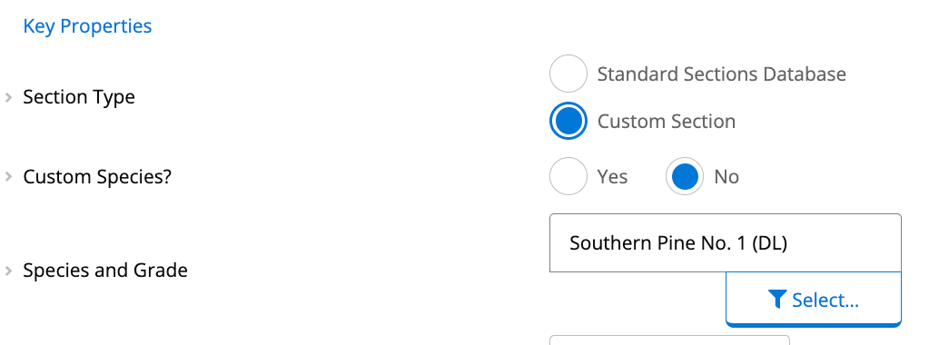
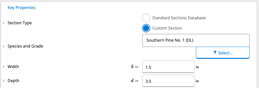
In Calcs.com, you can select a member from our Standard Sections Database or create your own Custom Section. See screenshot below for how selecting a Custom Section will modify your screen interface. Our Standard Sections Database is constantly updated based on requests from users like yourself, and can be filtered down by Type, Manufacturer, Species, Nominal Size, and Grade. More on this in the Size and Grade section after this.
More often than not, you’ll likely be using our standard sections database when you’re designing your beam. If you’re working with rough sawn lumber or older, existing homes with true-to-size lumber (i.e., a 2x4 is actually 2in x 4in), then choosing the “Custom Section” will be most useful for you.
**Section Type**
In Calcs.com, you can select a member from our Standard Sections Database or create your own Custom Section. See screenshot below for how selecting a Custom Section will modify your screen interface. Our Standard Sections Database is constantly updated based on requests from users like yourself, and can be filtered down by Type, Manufacturer, Species, Nominal Size, and Grade. More on this in the Size and Grade section after this.
More often than not, you’ll likely be using our standard sections database when you’re designing your beam. If you’re working with rough sawn lumber or older, existing homes with true-to-size lumber (i.e., a 2x4 is actually 2in x 4in), then choosing the “Custom Section” will be most useful for you.
 **Size and Grade**
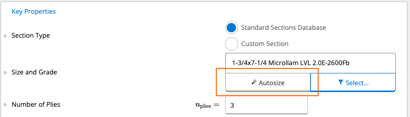
When sizing a beam in Calcs.com, the two ways to find your most optimal member are by using [Preferred Sections and Autosize](/docs/projects/preferred-sections/use-preferred-sections-autosize), or by using the [Member Selector](/docs/running-calculations/member-selector/index) within the calculator.
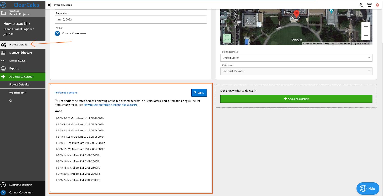
Prior to using Preferred Sections and Autosize, you’ll need to set up your Preferred Sections in Project Details. This feature will select the most optimal/efficient member out of your preferred sections. Calcs.com will also alert you here if none of your preferred sections will pass. See screenshot below.
**Size and Grade**
When sizing a beam in Calcs.com, the two ways to find your most optimal member are by using [Preferred Sections and Autosize](/docs/projects/preferred-sections/use-preferred-sections-autosize), or by using the [Member Selector](/docs/running-calculations/member-selector/index) within the calculator.
Prior to using Preferred Sections and Autosize, you’ll need to set up your Preferred Sections in Project Details. This feature will select the most optimal/efficient member out of your preferred sections. Calcs.com will also alert you here if none of your preferred sections will pass. See screenshot below.
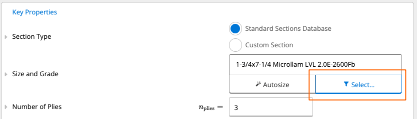
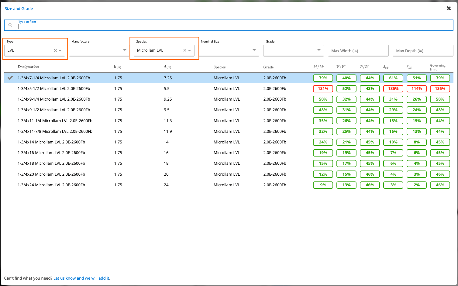
 Using the Member Selector within the calculator does not require you to have set up preferred sections. In this case, you can use as many or as few of the filters provided to see the member types you’re interested in. Notice you also see the real-time [utilization percentages in green, yellow, and red](/docs/running-calculations/checking-results/measuring-utilization-or-adequacy-design) showing you which beams pass or fail. This way, you can quickly use your engineering judgment if you’d like to bump up or down a size.
Notice in the second screenshot below that the Member Selector has been filtered to only show Microllam LVL’s. This way, you can quickly choose the member you am most comfortable with.
Using the Member Selector within the calculator does not require you to have set up preferred sections. In this case, you can use as many or as few of the filters provided to see the member types you’re interested in. Notice you also see the real-time [utilization percentages in green, yellow, and red](/docs/running-calculations/checking-results/measuring-utilization-or-adequacy-design) showing you which beams pass or fail. This way, you can quickly use your engineering judgment if you’d like to bump up or down a size.
Notice in the second screenshot below that the Member Selector has been filtered to only show Microllam LVL’s. This way, you can quickly choose the member you am most comfortable with.
 **Number of Plies**
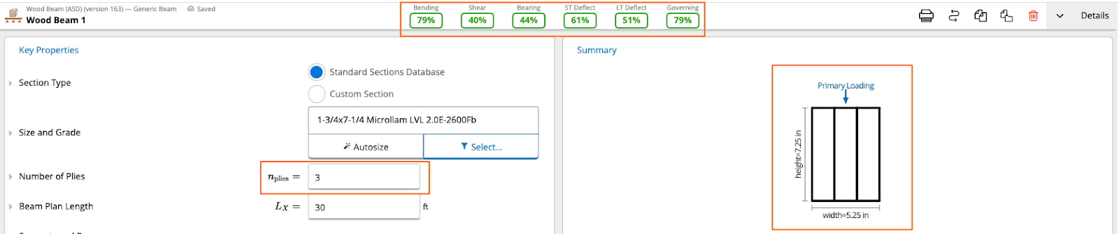
This is the total number of boards fastened flat side to flat side. Note that the bending axis specified remains specified relative to individual boards. E.g. if 5 plies of 2x6’s are used, the X-axis for bending remains the same as if there was only one board.
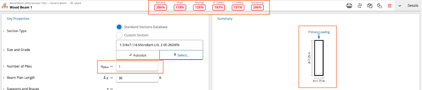
You can use this field to optimize your design after you input all required information. Alternatively, if your project involves an existing beam where you know how many plies there are, you can input that information right off the bat. See two screenshots below showing a beam with (1) ply, and then (3) plies, respectively.
**Number of Plies**
This is the total number of boards fastened flat side to flat side. Note that the bending axis specified remains specified relative to individual boards. E.g. if 5 plies of 2x6’s are used, the X-axis for bending remains the same as if there was only one board.
You can use this field to optimize your design after you input all required information. Alternatively, if your project involves an existing beam where you know how many plies there are, you can input that information right off the bat. See two screenshots below showing a beam with (1) ply, and then (3) plies, respectively.
 **Beam Plan Length**
The horizontal plan length of the beam (that is, not accounting for any slope if present).
**Supports and Braces**
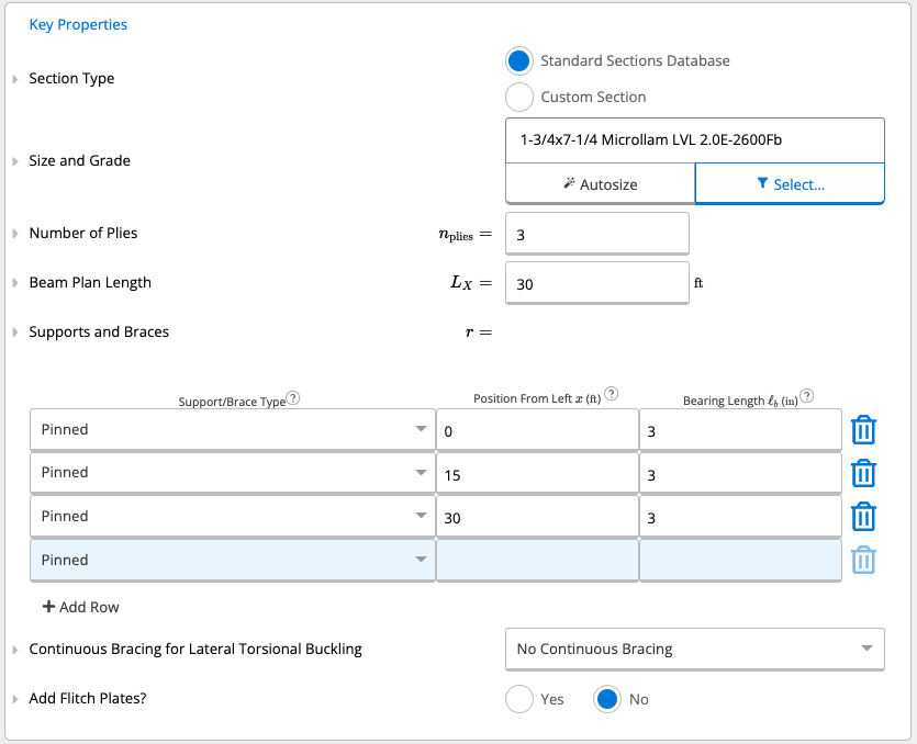
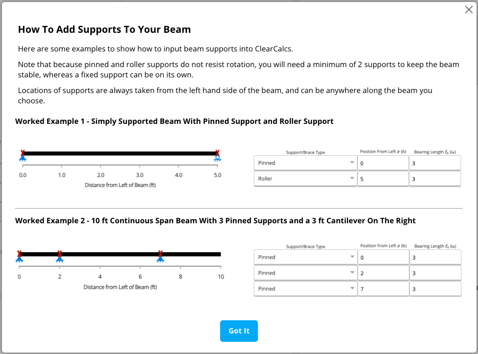
Position from leftmost of the beam of each support along the beam. Note that the first support does not have to be equal to 0 and the last support does not have to be the length of the beam (ie, a double cantilever scenario). To ignore bearing calculations, enter 0 as bearing length.
You can check out [this article here](/docs/running-calculations/setting-up-a-calculation/geometry-and-supports/enter-beam-supports#imperial-units) that walks you through how to input Supports and Braces into a beam calculator in Calcs.com.
A few important points to note:
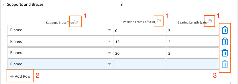
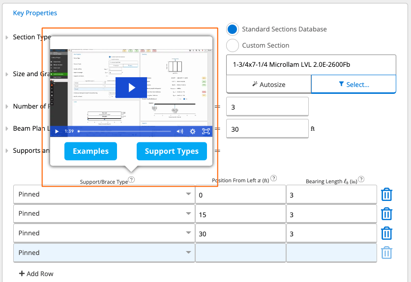
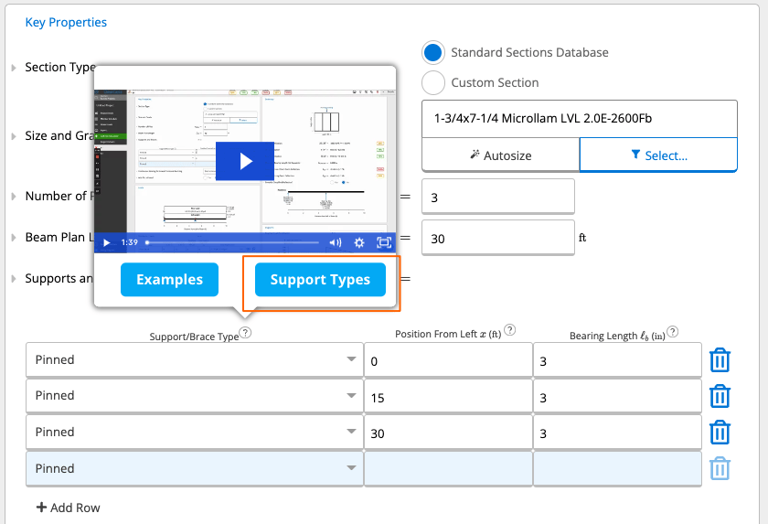
1. Hover over the question marks next to the “Support/Brace Type”, “Position from Left (ft)”, and “Bearing Length (ft)” to see some additional in-app help content. Shown below in screenshots for reference.
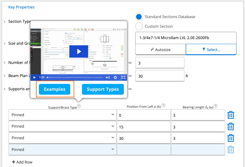
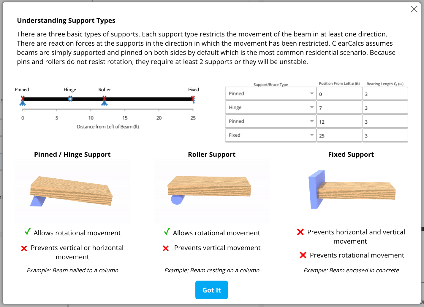
1. Curious what the difference between Pinned, Fixed, Roller, etc. support types are? We’ve got you covered! Take a look at the last screenshot in this “Supports and Braces” section.
2. The most conservative and generally most appropriate option is to use a Pinned or Roller support in Wood Beams, which is why we default to Pinned in our beam calculators.
2. Click the “+ Add Row” button to add a new row (i.e., add another support) to create a multi-span beam within Calcs.com.
1. You can add as many supports as you’d like in a Calcs.com beam calculator.
3. If you ever add a support that you didn’t mean to add - or if you want to get rid of one to see how your beam performs - simply hit that trash can icon on the right hand side of the row to delete the row.
**Beam Plan Length**
The horizontal plan length of the beam (that is, not accounting for any slope if present).
**Supports and Braces**
Position from leftmost of the beam of each support along the beam. Note that the first support does not have to be equal to 0 and the last support does not have to be the length of the beam (ie, a double cantilever scenario). To ignore bearing calculations, enter 0 as bearing length.
You can check out [this article here](/docs/running-calculations/setting-up-a-calculation/geometry-and-supports/enter-beam-supports#imperial-units) that walks you through how to input Supports and Braces into a beam calculator in Calcs.com.
A few important points to note:
1. Hover over the question marks next to the “Support/Brace Type”, “Position from Left (ft)”, and “Bearing Length (ft)” to see some additional in-app help content. Shown below in screenshots for reference.
1. Curious what the difference between Pinned, Fixed, Roller, etc. support types are? We’ve got you covered! Take a look at the last screenshot in this “Supports and Braces” section.
2. The most conservative and generally most appropriate option is to use a Pinned or Roller support in Wood Beams, which is why we default to Pinned in our beam calculators.
2. Click the “+ Add Row” button to add a new row (i.e., add another support) to create a multi-span beam within Calcs.com.
1. You can add as many supports as you’d like in a Calcs.com beam calculator.
3. If you ever add a support that you didn’t mean to add - or if you want to get rid of one to see how your beam performs - simply hit that trash can icon on the right hand side of the row to delete the row.
 **Continuous Bracing for Lateral Torsional Buckling**
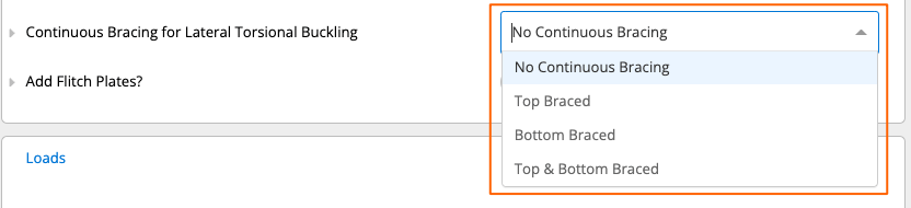
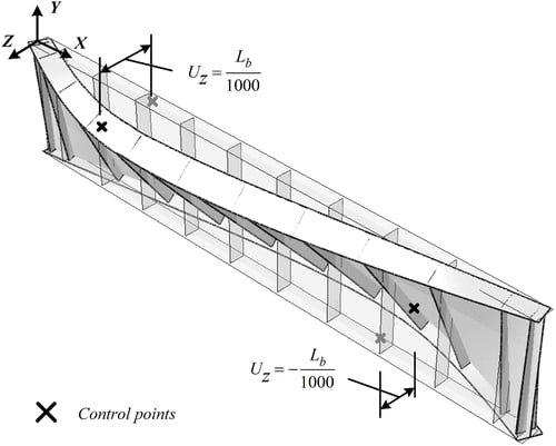
The top flange being continuously braced will prevent lateral torsional buckling in positive bending, and bottom flange bracing will prevent LTB in negative bending. If the beam is fully braced, then lateral torsional buckling calculations will not be performed. For dimensional lumber, the NDS 2018 (section 4.4.1) provides a requirement for a beam to be considered fully braced.
For reference, selecting “No Continuous Bracing” is the most conservative option. A common scenario for selecting “Top Braced” would be a floor joist or roof rafter where the floorboards or roof itself will prevent the beam from buckling laterally.
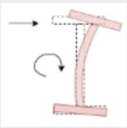
Check out the second screenshot below for a visual representation of what lateral torsional buckling means. ([Reference Here](https://ascelibrary.org/doi/abs/10.1061/%28ASCE%29ST.1943-541X.0003294))
**Continuous Bracing for Lateral Torsional Buckling**
The top flange being continuously braced will prevent lateral torsional buckling in positive bending, and bottom flange bracing will prevent LTB in negative bending. If the beam is fully braced, then lateral torsional buckling calculations will not be performed. For dimensional lumber, the NDS 2018 (section 4.4.1) provides a requirement for a beam to be considered fully braced.
For reference, selecting “No Continuous Bracing” is the most conservative option. A common scenario for selecting “Top Braced” would be a floor joist or roof rafter where the floorboards or roof itself will prevent the beam from buckling laterally.
Check out the second screenshot below for a visual representation of what lateral torsional buckling means. ([Reference Here](https://ascelibrary.org/doi/abs/10.1061/%28ASCE%29ST.1943-541X.0003294))
 **Add Flitch Plates?**
Set this to “Yes” if you would like to add flitch plates to the member. If you’re unfamiliar with what flitch plates are and how to design a flitch beam, check out [this article here](/docs/calculators/us/beams/flitch-beam-design).
**Add Flitch Plates?**
Set this to “Yes” if you would like to add flitch plates to the member. If you’re unfamiliar with what flitch plates are and how to design a flitch beam, check out [this article here](/docs/calculators/us/beams/flitch-beam-design).
 **Load Diagram**
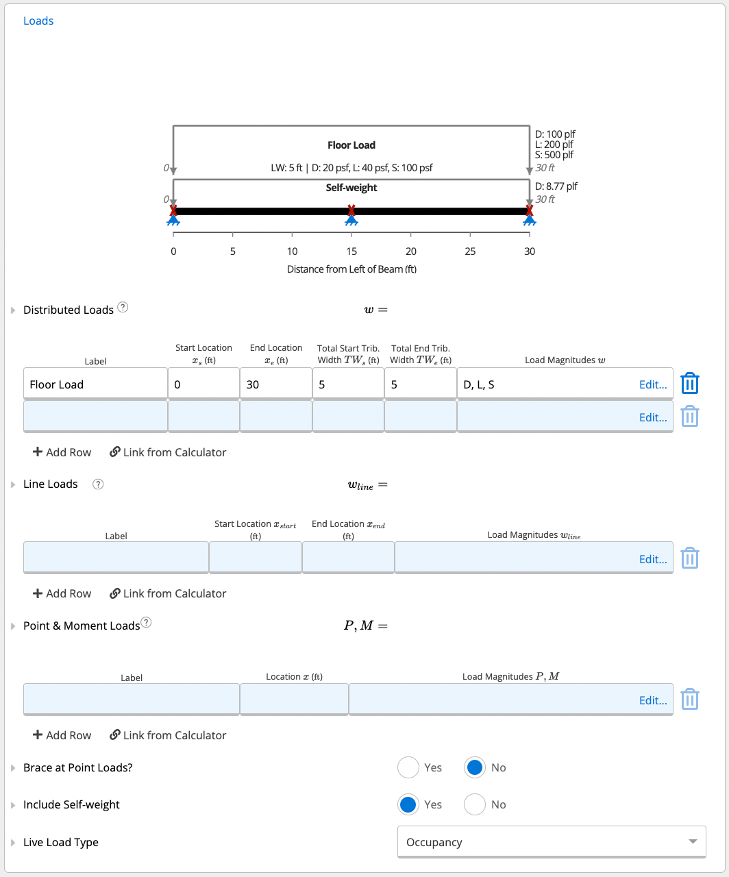
The load diagram provides a live illustration of the beam and the assigned loading.
**Distributed Loads**
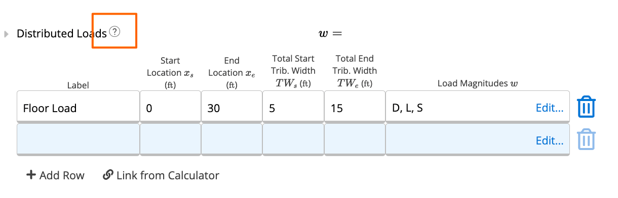
A distributed load is measured in pounds-per-square-foot (psf). This load may start and end at any location. A partially distributed load (PDL), for example, would start and/or end at a location within the beam. See screenshot below.
**Load Diagram**
The load diagram provides a live illustration of the beam and the assigned loading.
**Distributed Loads**
A distributed load is measured in pounds-per-square-foot (psf). This load may start and end at any location. A partially distributed load (PDL), for example, would start and/or end at a location within the beam. See screenshot below.
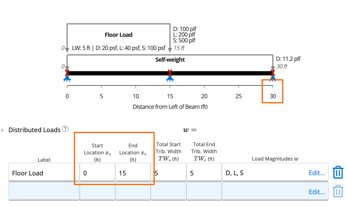 Note also that the start and end magnitudes may differ. A variable distributed load (VDL) is a triangular load, in which the start magnitude does not equal the end magnitude. You can set this by changing the tributary width at the start and at the end of the load, as shown below. An example of this would be for a hip rafter. Note that all distributed loads entered in this table are applied perpendicular to the beam. Each row of this table represents a single pair of start and end locations, but as many rows as desired may be created.
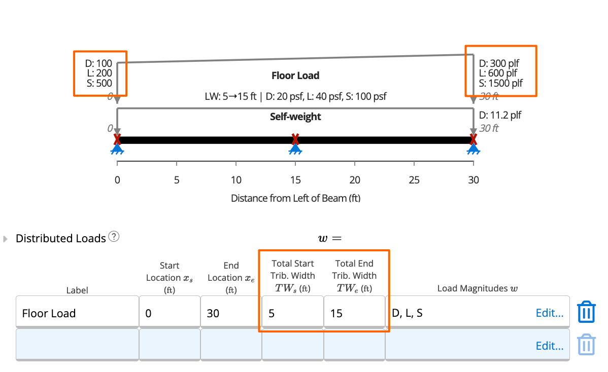 You can check out [this article here](/docs/running-calculations/setting-up-a-calculation/loads/enter-distributed-loads#imperial-units) that walks you through how to input Distributed Loads into a Calcs.com calculator, plus [this article here](/docs/running-calculations/setting-up-a-calculation/loads/enter-loads-patch-point-moment-axial-triangular-line) that expands upon the different load types.
A few important points to note:
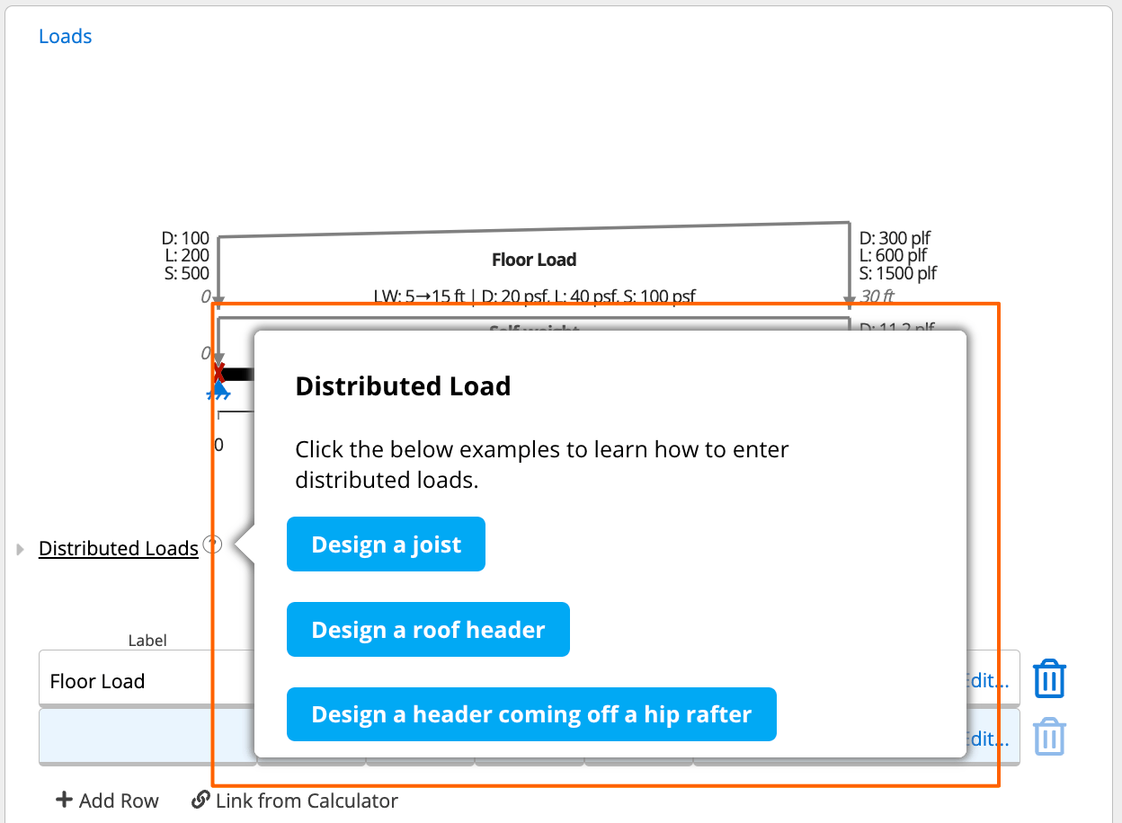
1. Hover over the question mark next to “Distributed Loads” to see some additional in-app help content. Shown below in screenshots for your reference.
2. Click the “+ Add Row” button to add a new row (i.e., add another load) to create an unlimited number of load combinations in ClearCallcs.
3. You can add as many loads as you’d like in a Calcs.com beam calculator.
4. If you ever add a load that you didn’t mean to add - or if you want to get rid of one to see how your beam performs - simply hit the trash can icon on the right hand side of the row to delete the row.
You can check out [this article here](/docs/running-calculations/setting-up-a-calculation/loads/enter-distributed-loads#imperial-units) that walks you through how to input Distributed Loads into a Calcs.com calculator, plus [this article here](/docs/running-calculations/setting-up-a-calculation/loads/enter-loads-patch-point-moment-axial-triangular-line) that expands upon the different load types.
A few important points to note:
1. Hover over the question mark next to “Distributed Loads” to see some additional in-app help content. Shown below in screenshots for your reference.
2. Click the “+ Add Row” button to add a new row (i.e., add another load) to create an unlimited number of load combinations in ClearCallcs.
3. You can add as many loads as you’d like in a Calcs.com beam calculator.
4. If you ever add a load that you didn’t mean to add - or if you want to get rid of one to see how your beam performs - simply hit the trash can icon on the right hand side of the row to delete the row.
 **Line Loads**
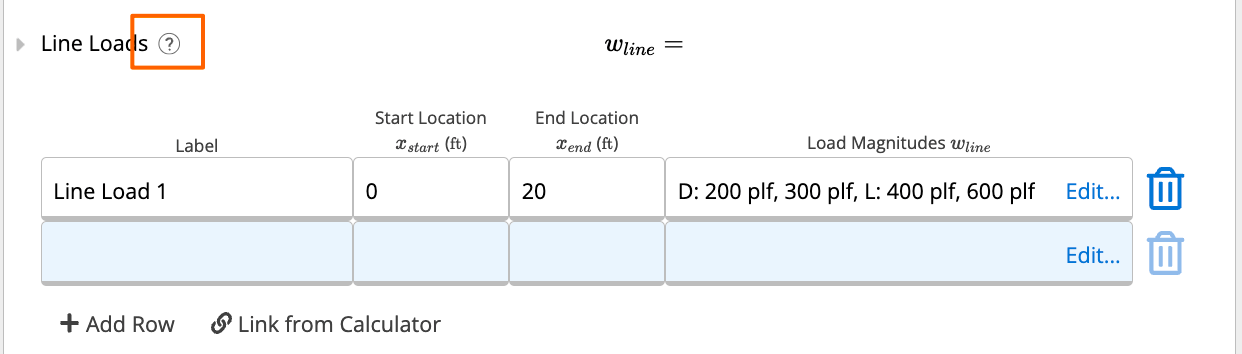
A line load is measured in pounds-per-lineal-foot (plf). This load may start and end at any location. A partially distributed load (PDL), for example, would start and/or end at a location within the beam. See screenshot below.
**Line Loads**
A line load is measured in pounds-per-lineal-foot (plf). This load may start and end at any location. A partially distributed load (PDL), for example, would start and/or end at a location within the beam. See screenshot below.
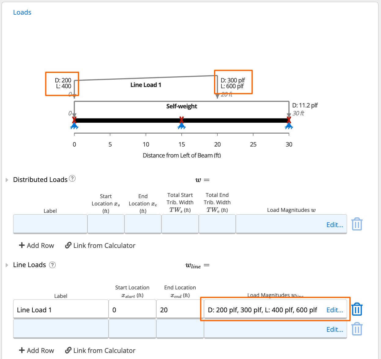
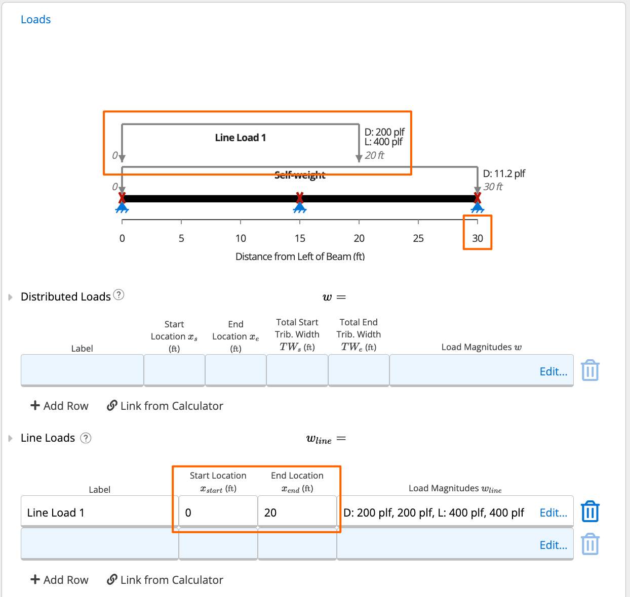 Note also that the start and end magnitudes may differ. A triangular load is a load in which the start magnitude does not equal the end magnitude. Note that all line loads entered in this table are applied perpendicular to the beam. Each row of this table represents a single pair of start and end locations, but as many rows as desired may be created.
 A few important points to note:
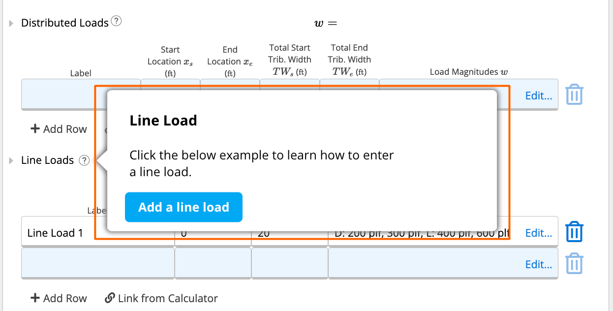
1. Hover over the question mark next to “Line Loads” to see some additional in-app help content. Shown below in screenshots for your reference.
2. Click that “+ Add Row” button to add a new row (i.e., add another load) to create an unlimited number of load combinations in ClearCallcs.
3. You can add as many, or as little, load combinations as you’d like in a Calcs.com beam calculator.
4. If you ever add a load that you didn’t mean to add - or if you want to get rid of one to see how your beam performs - simply hit that trash can icon on the right hand side of the row to delete the row.
A few important points to note:
1. Hover over the question mark next to “Line Loads” to see some additional in-app help content. Shown below in screenshots for your reference.
2. Click that “+ Add Row” button to add a new row (i.e., add another load) to create an unlimited number of load combinations in ClearCallcs.
3. You can add as many, or as little, load combinations as you’d like in a Calcs.com beam calculator.
4. If you ever add a load that you didn’t mean to add - or if you want to get rid of one to see how your beam performs - simply hit that trash can icon on the right hand side of the row to delete the row.
 **Point & Moment Loads**
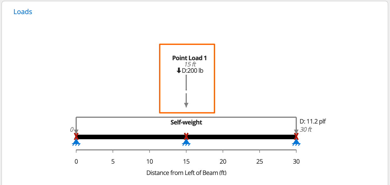
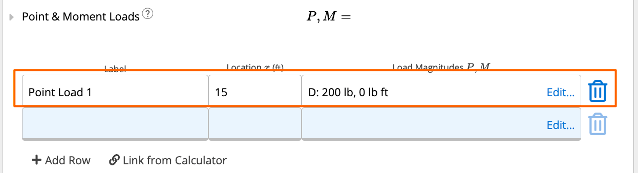
A point load acts over a relatively small area. For example, a weight that has been hung from a ceiling or a column that is supported by a beam. This load may be of any magnitude, and may be located at any point along the beam. Note that all point loads entered in this table are applied perpendicular to the beam.
A moment load causes the rotation of a member about an axis. There are few examples of pure moment loads applied in a typical structure, though the most common occurs if there is a fixed connection between a beam and column. Moment loads are also often used to idealize the effect of horizontal loads on cantilevered attachments on a beam (e.g., a satellite antenna attached to a roof rafter subjected to wind loads).
Another individual beam or column bearing on or connected to this one may be linked into this table by clicking on the chain link icon on the right side of the table. Note that if you wish to connect a repeating joist or rafter, it may be easier to link these as a Line Load using the table above instead.
Each row of this table represents a single location, but as many rows as desired may be created. Usually, an ‘Alternative Minimum Live Load’ will appear here by default. This Alternative Minimum Live Load, with load type ‘L2’, is NOT applied at the same time as the normal live load. For some types of surfaces, the building codes require that beams be able to support at least a minimum concentrated live load, regardless of the normal live load, and that is this value. If it is blank (zero), then the default surface type you have selected in your Project Defaults does not require an alternative minimum live load.
**Point & Moment Loads**
A point load acts over a relatively small area. For example, a weight that has been hung from a ceiling or a column that is supported by a beam. This load may be of any magnitude, and may be located at any point along the beam. Note that all point loads entered in this table are applied perpendicular to the beam.
A moment load causes the rotation of a member about an axis. There are few examples of pure moment loads applied in a typical structure, though the most common occurs if there is a fixed connection between a beam and column. Moment loads are also often used to idealize the effect of horizontal loads on cantilevered attachments on a beam (e.g., a satellite antenna attached to a roof rafter subjected to wind loads).
Another individual beam or column bearing on or connected to this one may be linked into this table by clicking on the chain link icon on the right side of the table. Note that if you wish to connect a repeating joist or rafter, it may be easier to link these as a Line Load using the table above instead.
Each row of this table represents a single location, but as many rows as desired may be created. Usually, an ‘Alternative Minimum Live Load’ will appear here by default. This Alternative Minimum Live Load, with load type ‘L2’, is NOT applied at the same time as the normal live load. For some types of surfaces, the building codes require that beams be able to support at least a minimum concentrated live load, regardless of the normal live load, and that is this value. If it is blank (zero), then the default surface type you have selected in your Project Defaults does not require an alternative minimum live load.
 **Brace at Point Loads?**
Choose whether or not to add braces against lateral torsional buckling at point loads. An applied load on a beam can cause lateral displacement and rotation about the plan of the section. Lateral restraints/braces aim to prevent this by restraining the compression flange. Secondary beams are commonly used as discrete lateral restraints where those secondary beams provide lateral support to the primary beam at their connection points.
**Brace at Point Loads?**
Choose whether or not to add braces against lateral torsional buckling at point loads. An applied load on a beam can cause lateral displacement and rotation about the plan of the section. Lateral restraints/braces aim to prevent this by restraining the compression flange. Secondary beams are commonly used as discrete lateral restraints where those secondary beams provide lateral support to the primary beam at their connection points.
 **Include Self-weight**
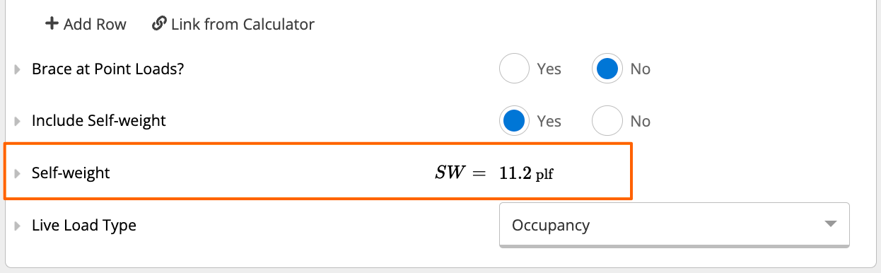
Choose whether or not to include the weight of the member being analyzed in the calculations. By default, self-weight is considered in all calculations. However, many span tables and design guides instead include self-weight into the design dead load, in which case leaving self-weight on in Calcs.com may lead to a small discrepancy.
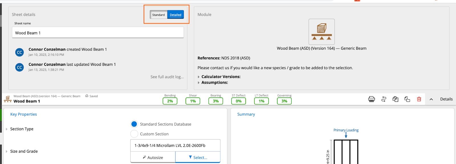
As a tip - you can turn on “detailed mode” in your wood beam calculator and see the self weight of your beam in the loads section of your calculator.
**Include Self-weight**
Choose whether or not to include the weight of the member being analyzed in the calculations. By default, self-weight is considered in all calculations. However, many span tables and design guides instead include self-weight into the design dead load, in which case leaving self-weight on in Calcs.com may lead to a small discrepancy.
As a tip - you can turn on “detailed mode” in your wood beam calculator and see the self weight of your beam in the loads section of your calculator.
 **Live Load Type**
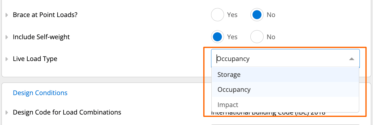
Select the type of live load most applicable to your design. In most cases, this will be a standard occupancy live load. For instance, you would expect the storage live load type when considering an attic, and the impact live load type when designing vehicle barriers. The type of live load affects the time influence factors in wood members (CD in ASD, λ in LRFD).
**Live Load Type**
Select the type of live load most applicable to your design. In most cases, this will be a standard occupancy live load. For instance, you would expect the storage live load type when considering an attic, and the impact live load type when designing vehicle barriers. The type of live load affects the time influence factors in wood members (CD in ASD, λ in LRFD).
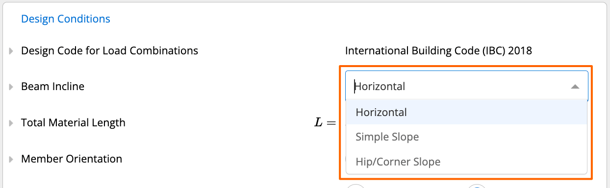
 **Beam Incline**
If your beam is on an incline or a hip/corner slope, this is where you’ll tell Calcs.com. This field will default based on the wood beam preset you’ve selected.
**Beam Incline**
If your beam is on an incline or a hip/corner slope, this is where you’ll tell Calcs.com. This field will default based on the wood beam preset you’ve selected.
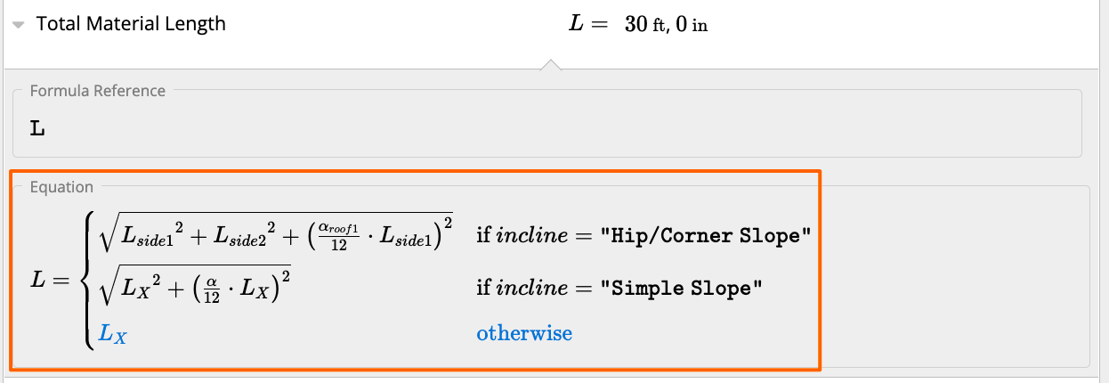
 **Total Material Length**
Depending on your beam incline you’ve chosen from above, the Total Material Length will be calculated using Pythagorean’s Theorem (see screenshot below). In this case, we have a horizontal beam so Pythagorean’s Theorem isn’t needed, as shown by the blue “L\_x”.
**Total Material Length**
Depending on your beam incline you’ve chosen from above, the Total Material Length will be calculated using Pythagorean’s Theorem (see screenshot below). In this case, we have a horizontal beam so Pythagorean’s Theorem isn’t needed, as shown by the blue “L\_x”.
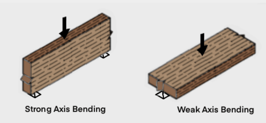
 **Member Orientation**
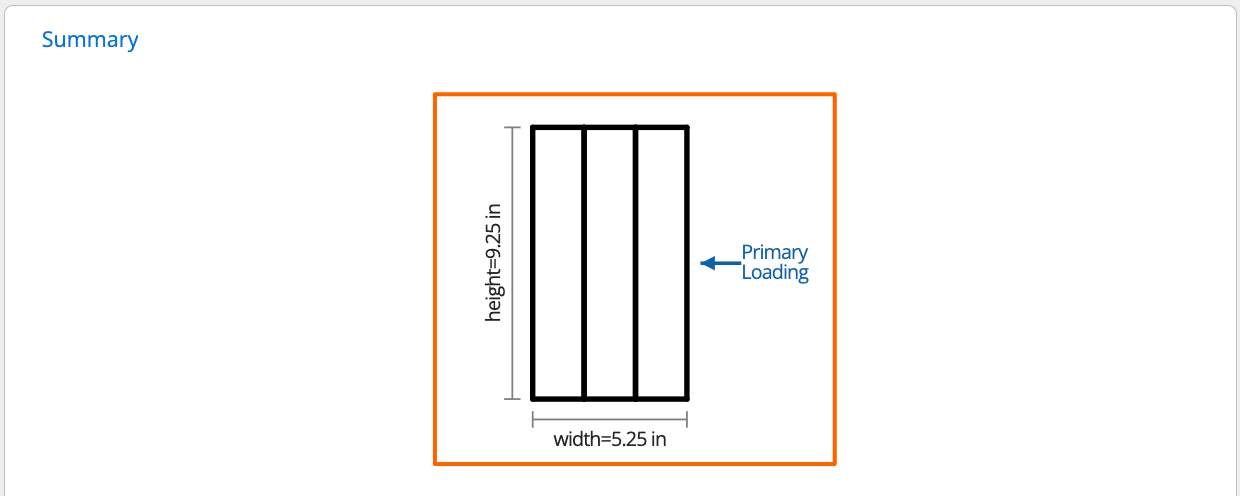
Choose whether the member is loaded such that it bends about the x or y axis; X-X refers to the axis which has the higher moment of inertia (“joist orientation”) whereas Y-Y refers to the weaker moment of inertia (“plank or flat orientation”). Notice in the second and third screenshots how this field impacts your beam loading in “Summary”.
**Member Orientation**
Choose whether the member is loaded such that it bends about the x or y axis; X-X refers to the axis which has the higher moment of inertia (“joist orientation”) whereas Y-Y refers to the weaker moment of inertia (“plank or flat orientation”). Notice in the second and third screenshots how this field impacts your beam loading in “Summary”.

 **Repeating Member?**
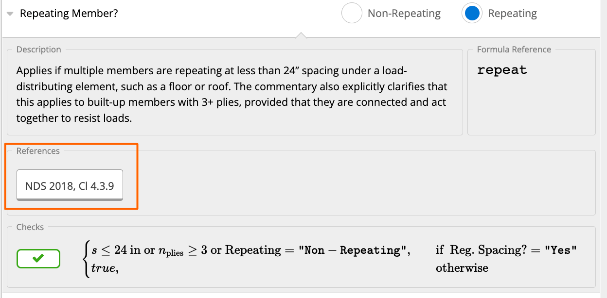
Applies if multiple members are repeating at less than 24” spacing under a load-distributing element, such as a floor or roof. The commentary also explicitly clarifies that this applies to built-up members with 3+ plies, provided that they are connected and act together to resist loads. Note that Calcs.com will tell you which section of the NDS this field applies to in the screenshot below.
By default, if there’s more than 3 plies in your design, the repeating member factor will be applied.
**Repeating Member?**
Applies if multiple members are repeating at less than 24” spacing under a load-distributing element, such as a floor or roof. The commentary also explicitly clarifies that this applies to built-up members with 3+ plies, provided that they are connected and act together to resist loads. Note that Calcs.com will tell you which section of the NDS this field applies to in the screenshot below.
By default, if there’s more than 3 plies in your design, the repeating member factor will be applied.
 **Service Condition**
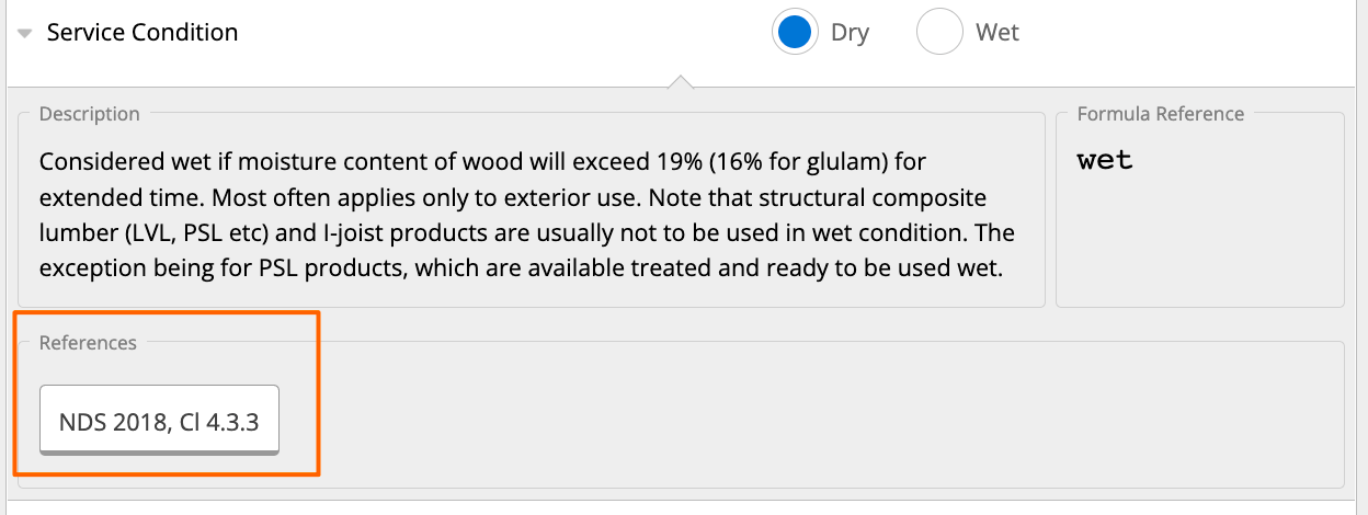
Considered wet if moisture content of wood will exceed 19% (16% for glulam) for extended time. Most often applies only to exterior use. Note that structural composite lumber (LVL, PSL etc) and I-joist products are usually not to be used in wet condition. The exception being for PSL products, which are available treated and ready to be used wet. Note that Calcs.com will tell you which section of the NDS this field applies to in the screenshot below.
**Service Condition**
Considered wet if moisture content of wood will exceed 19% (16% for glulam) for extended time. Most often applies only to exterior use. Note that structural composite lumber (LVL, PSL etc) and I-joist products are usually not to be used in wet condition. The exception being for PSL products, which are available treated and ready to be used wet. Note that Calcs.com will tell you which section of the NDS this field applies to in the screenshot below.
 **Temperature Range**
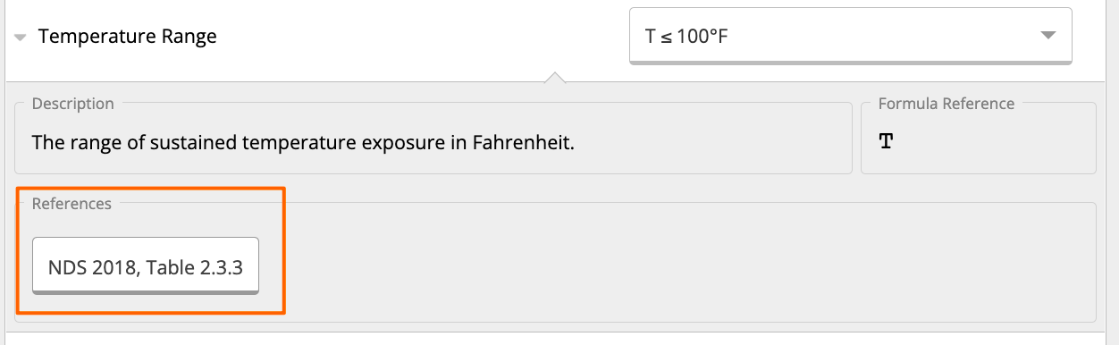
The range of sustained temperature exposure in Fahrenheit. Note that Calcs.com will tell you which section of the NDS this field applies to in the screenshot below.
**Temperature Range**
The range of sustained temperature exposure in Fahrenheit. Note that Calcs.com will tell you which section of the NDS this field applies to in the screenshot below.
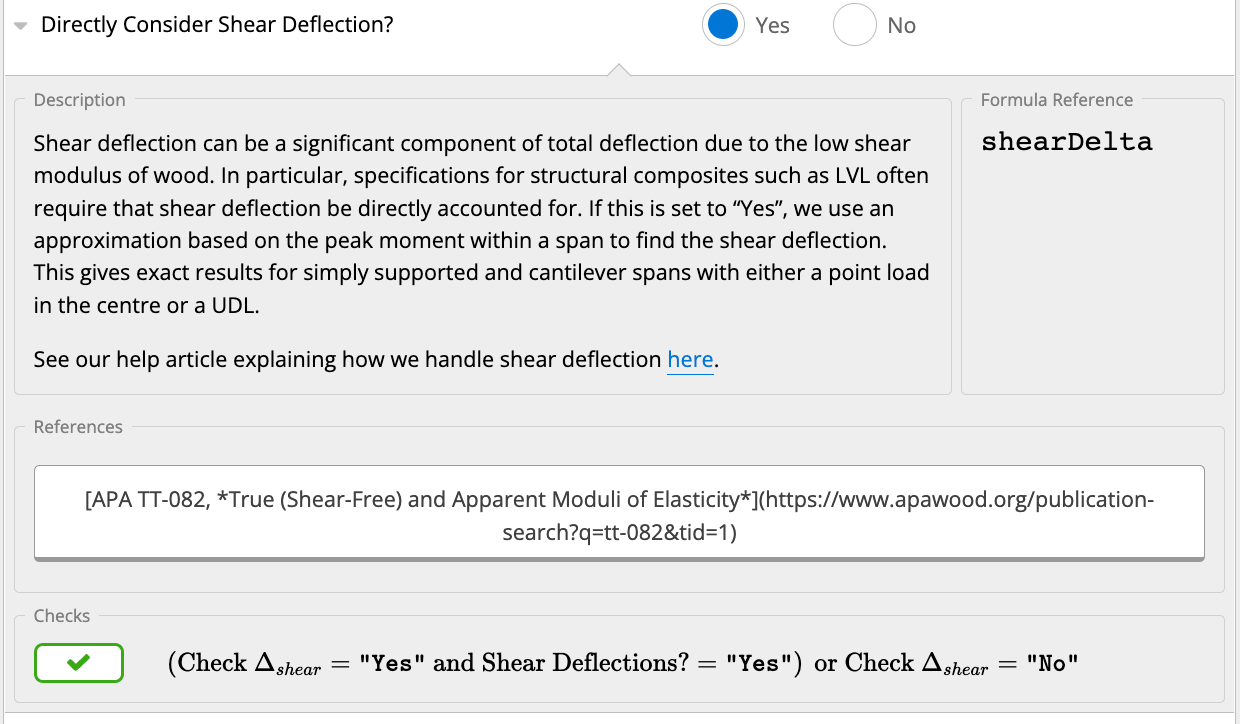
 **Directly Consider Shear Deflection?**
Shear deflection can be a significant component of total deflection due to the low shear modulus of wood. In particular, specifications for structural composites such as LVL often require that shear deflection be directly accounted for. If this is set to “Yes”, we use an approximation based on the peak moment within a span to find the shear deflection. This gives exact results for simply supported and cantilever spans with either a point load in the center or a UDL.
**Directly Consider Shear Deflection?**
Shear deflection can be a significant component of total deflection due to the low shear modulus of wood. In particular, specifications for structural composites such as LVL often require that shear deflection be directly accounted for. If this is set to “Yes”, we use an approximation based on the peak moment within a span to find the shear deflection. This gives exact results for simply supported and cantilever spans with either a point load in the center or a UDL.
 **Deflection Limit Absolute Limit**
The hard maximum deflection allowed for the beam, regardless of span length. Normally, your local building code will dictate this.
Some common examples when you’ll use this absolute limit is when you’re designing a floor joist in an expensive home, or when you’re designing a header above french doors. In both cases, you may want to ensure the beams won’t deflect more than 0.25” no matter what your “L/” checks show you.
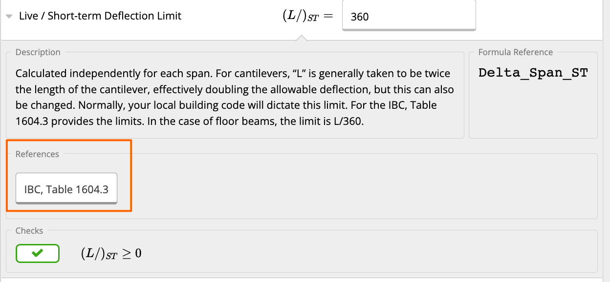
**Live / Short-term Deflection Limit**
Calculated independently for each span. For cantilevers, “L” is generally taken to be twice the length of the cantilever, effectively doubling the allowable deflection, but this can also be changed. Normally, your local building code will dictate this limit. For the IBC, Table 1604.3 provides the limits. In the case of floor beams, the limit is L/360.
Loads that will be included in your Live / Short-term Deflection calculations are:
* Live and roof live load
* Snow load
* 0.42 times the ultimate wind load (the 0.42 factor converts to service-level loads)
**Deflection Limit Absolute Limit**
The hard maximum deflection allowed for the beam, regardless of span length. Normally, your local building code will dictate this.
Some common examples when you’ll use this absolute limit is when you’re designing a floor joist in an expensive home, or when you’re designing a header above french doors. In both cases, you may want to ensure the beams won’t deflect more than 0.25” no matter what your “L/” checks show you.
**Live / Short-term Deflection Limit**
Calculated independently for each span. For cantilevers, “L” is generally taken to be twice the length of the cantilever, effectively doubling the allowable deflection, but this can also be changed. Normally, your local building code will dictate this limit. For the IBC, Table 1604.3 provides the limits. In the case of floor beams, the limit is L/360.
Loads that will be included in your Live / Short-term Deflection calculations are:
* Live and roof live load
* Snow load
* 0.42 times the ultimate wind load (the 0.42 factor converts to service-level loads)
 **Long Term Deflection Limit**
Calculated independently for each span. For cantilevers, “L” is generally taken to be twice the length of the cantilever, effectively doubling the allowable deflection, but this can also be changed. Normally, your local building code will dictate this limit. For the IBC, Table 1604.3 provides the limits. In the case of floor beams, the limit is L/360.
Loads that will be included in your Long-term Deflection calculations are:
* Creep component of the dead load (50% of the instant deflection in most cases) and the full live load
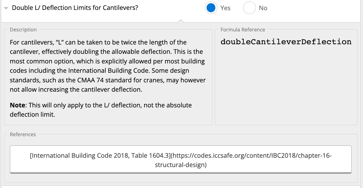
**Double L/ Deflection Limits for Cantilevers**
For cantilevers, “L” can be taken to be twice the length of the cantilever, effectively doubling the allowable deflection. This is the most common option, which is explicitly allowed per most building codes including the International Building Code. Some design standards, such as the CMAA 74 standard for cranes, may however not allow increasing the cantilever deflection.
Note: This will only apply to the L/ deflection, not the absolute deflection limit.
**Long Term Deflection Limit**
Calculated independently for each span. For cantilevers, “L” is generally taken to be twice the length of the cantilever, effectively doubling the allowable deflection, but this can also be changed. Normally, your local building code will dictate this limit. For the IBC, Table 1604.3 provides the limits. In the case of floor beams, the limit is L/360.
Loads that will be included in your Long-term Deflection calculations are:
* Creep component of the dead load (50% of the instant deflection in most cases) and the full live load
**Double L/ Deflection Limits for Cantilevers**
For cantilevers, “L” can be taken to be twice the length of the cantilever, effectively doubling the allowable deflection. This is the most common option, which is explicitly allowed per most building codes including the International Building Code. Some design standards, such as the CMAA 74 standard for cranes, may however not allow increasing the cantilever deflection.
Note: This will only apply to the L/ deflection, not the absolute deflection limit.
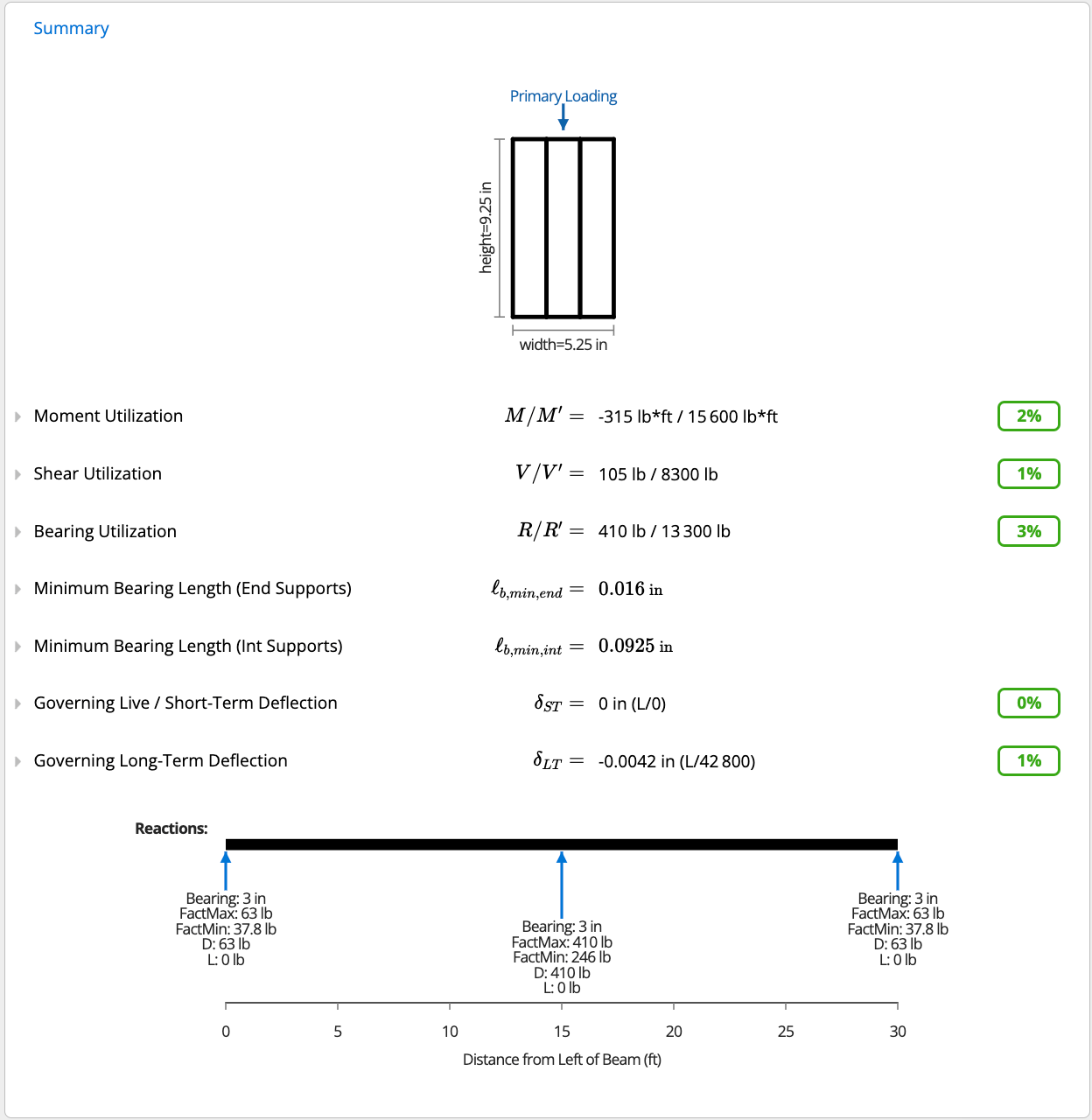 In this Summary section, Calcs.com is looking at your utilization percentages (i.e., demand divided by capacity of your beam) for Moment, Shear, Bearing, Short-Term Deflection, and Long-Term Deflection. Note as well that Calcs.com is performing the calculations to provide you what the minimum bearing length needs to be so your beam does not fail due to bearing.
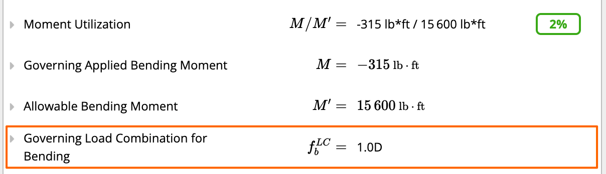
When you swap to “Detailed” mode, Calcs.com will also show you the governing load combination. Note that the green, yellow, and/or red utilization percentages will always be based on the worst-case (governing) load combination that your beam will need to withstand.
In this Summary section, Calcs.com is looking at your utilization percentages (i.e., demand divided by capacity of your beam) for Moment, Shear, Bearing, Short-Term Deflection, and Long-Term Deflection. Note as well that Calcs.com is performing the calculations to provide you what the minimum bearing length needs to be so your beam does not fail due to bearing.
When you swap to “Detailed” mode, Calcs.com will also show you the governing load combination. Note that the green, yellow, and/or red utilization percentages will always be based on the worst-case (governing) load combination that your beam will need to withstand.
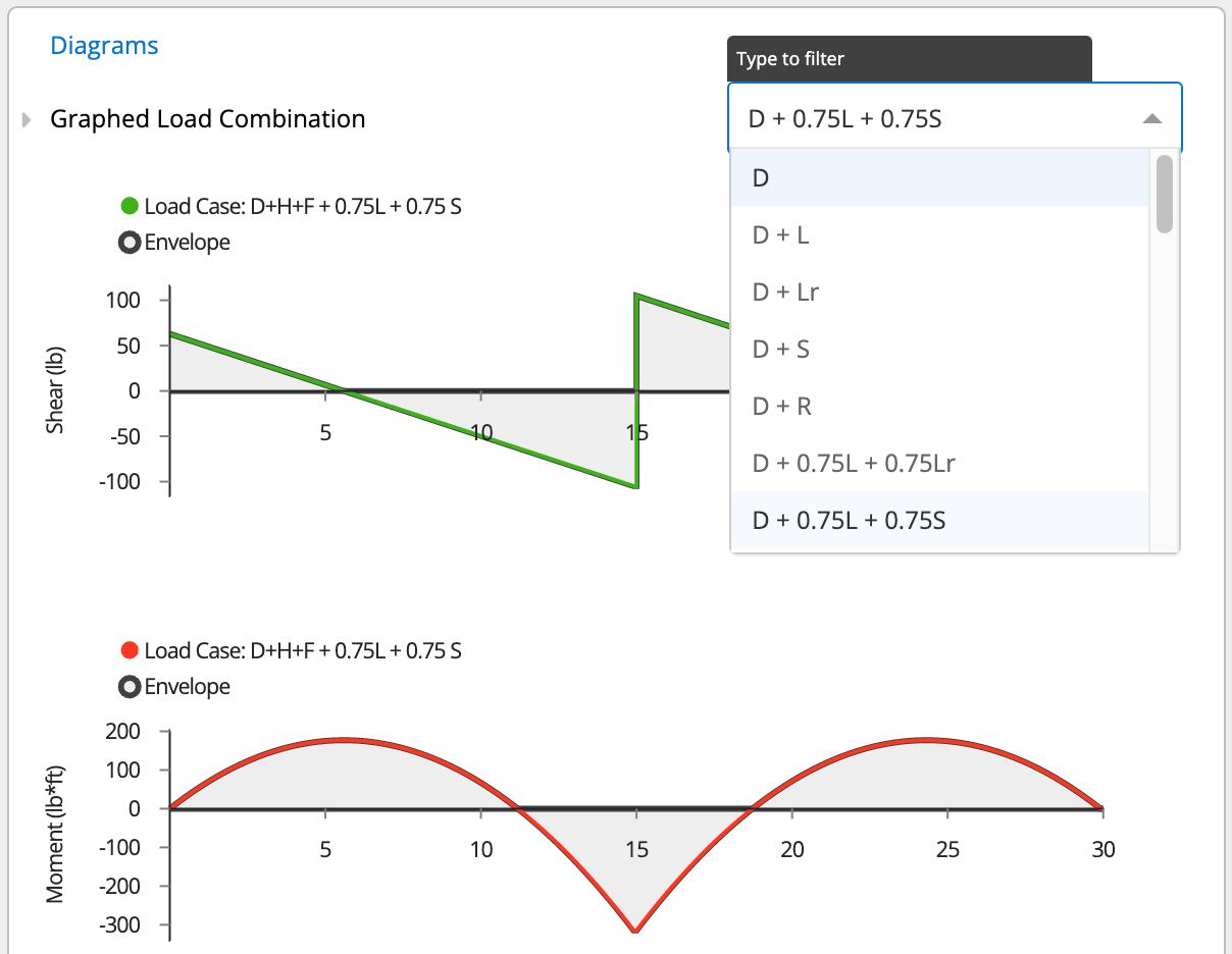
 Finally, the right side of the Calcs.com screen will also show you your shear, moment, and deflection diagrams. The black line on the graphs (the “envelope”) show the worst-case (governing) load combination, while the green, red, and blue lines in the graphs show the graphed load combination. This can be modified in the dropdown shown in the first screenshot below.
 Interested in learning more about the US Wood Beam calculator? Check out the links below:
* [How to Design a Wood Beam, including Joists, Rafters, and Ridge Beams to NDS 2018](/docs/calculators/us/beams/timberBeamASDNDS-2024)
Interested in learning more about the US Wood Beam calculator? Check out the links below:
* [How to Design a Wood Beam, including Joists, Rafters, and Ridge Beams to NDS 2018](/docs/calculators/us/beams/timberBeamASDNDS-2024)