> ## Documentation Index
> Fetch the complete documentation index at: https://calcs.com/docs/llms.txt
> Use this file to discover all available pages before exploring further.
# Design a Steel Base Plate (LRFD) to AISC 360-22
> Design steel column base plates and anchor rods to ACI 318-19 and AISC 360-22 per AISC Design Guide 1 (3rd Edition), with LRFD checks.
Base plate design receives column axial load directly, change the column load and the plate thickness and anchor check update automatically. Designs steel column base plates and anchor rods to ACI 318-19 and AISC 360-22 per AISC Design Guide 1, 3rd Edition, with full LRFD bearing, plate bending, and anchor limit state checks.
**Instantly create a new Steel Base Plate calculation by clicking here:**
[**Create Steel Base Plate Calculator**](https://calcs.com/new/sheet/steelBasePlateLRFDACI318-19)
*(This link automatically opens a new project and sheet in Calcs.com.)*
## Method & scope
| Property | Detail |
| ---------------- | --------------------------------------------------------------------------------------------------------------------------------------------------------------------------------------------------------------------------------------------------------------------------------------------------------------------------------------------------------------------------------------------------------- |
| Design standards | ACI 318-19, AISC 360-22, AISC Design Guide 1 (2024): Base Connection Design for Steel Structures - 3rd Edition |
| Regions | United States |
| What it checks | Load combinations, Concrete bearing capacity (AISC DG1 3rd ed., Cl. 3.1), Plate bending at bearing interface (AISC DG1 3rd ed., Cl. 3.3, 3.4), Plate bending at tension interface (AISC DG1 3rd ed., Cl. 3.3, 3.4), Anchor tensile limit states (ACI 318-19 Cl. 17.6), Anchor shear limit states (ACI 318-19 Cl. 17.7), Frictional shear capacity (ACI 318-19 Cl. 22.9), Minimum required plate thickness |
#### Assumptions and Limitations
**Biaxial Loading:** Biaxial loading is **not** considered simultaneously. Moment demands are assumed to act in their respective axes individually.
* The base plate is assumed to be rigid and resting in the center of the concrete pier.
* Group effects for tensile and shear are limited to the grouped anchors on one side of a plate.
* Cases where net tension is applied to the base plate are not currently supported.
For a complete list of all assumptions and technical limitations, please open the **Sheet Details** tab within the calculator.
#### Calculation method
The Steel Base Plate (LRFD) calculator uses AISC Design Guide 1, 3rd Edition (2024) for plate geometry and bending design, ACI 318-19 Chapter 17 for all anchor limit states, and ASCE 7-22 for LRFD load combinations. This is the current-code version of the base plate calculator.
##### Load combinations
Unfactored gravity, wind, and seismic load components are combined using ASCE 7-22 Chapter 2 LRFD combinations. The calculator evaluates each combination and reports the governing demand for every limit state, compressive axial typically governs bearing while the combination with minimum compression and maximum moment governs anchor tension.
##### Concrete bearing capacity (AISC DG1 3rd ed., Cl. 3.1)
The factored bearing strength:
phi × P\_p = phi\_c × 0.85 × f'c × A\_1 × sqrt(A\_2/A\_1)
where A\_2/A\_1 is the geometric confinement factor, capped at 4.0 when the concrete frustum is fully confined.
**Utilization** = P\_u / phi × P\_p ≤ 1.0
##### Plate bending at bearing interface (AISC DG1 3rd ed., Cl. 3.3, 3.4)
When the plate is in the small-moment regime (full bearing), the critical bending demand at the plate cantilever projections m and n is:
M\_u,pl = q × max(m, n)^2 / 2
where q is the factored bearing pressure per unit length. The required plate thickness is back-calculated from:
t\_min = sqrt(4 × M\_u,pl / (phi\_p × F\_y))
**Utilization** = M\_u,pl / phi × M\_n ≤ 1.0
##### Plate bending at tension interface (AISC DG1 3rd ed., Cl. 3.3, 3.4)
For large-moment conditions, anchor tension T\_u pulls upward on the plate and creates plate bending at the tension interface. The moment demand and required plate thickness at the tension face are checked independently in both axes.
##### Anchor tensile limit states (ACI 318-19 Cl. 17.6)
Five tensile failure modes are evaluated for the anchor group:
* **Steel tensile strength** (Cl. 17.6.1): phi × N\_sa = phi\_t × A\_se,N × f\_uta
* **Concrete breakout in tension** (Cl. 17.6.2): CCD projected area method with modification factors psi\_ec,N (eccentricity), psi\_ed,N (edge distance), psi\_c,N (cracking), and psi\_cp,N (post-installed)
* **Pullout** (Cl. 17.6.3): phi × N\_pn = phi × 8 × A\_brg × f'c per headed anchor
* **Side-face blowout** (Cl. 17.6.4): when h\_ef / c\_a1 ≥ 2.5
* **Interaction of shear and tension**: combined action ratio per Cl. 17.8
**Utilization** = N\_u / phi × N\_n,g ≤ 1.0
##### Anchor shear limit states (ACI 318-19 Cl. 17.7)
Shear failure modes evaluated in both principal axes:
* **Steel shear capacity** (Cl. 17.7.1): phi × V\_sa = phi\_v × 0.6 × A\_se,V × f\_uta
* **Concrete pryout** (Cl. 17.7.3): phi × V\_cp = phi × k\_cp × N\_cbg
* **Concrete shear breakout** (Cl. 17.7.2): projected area A\_Vc with edge distance and eccentricity modification factors
**Utilization** = V\_u / phi × V\_n,g ≤ 1.0
##### Frictional shear capacity (ACI 318-19 Cl. 22.9)
Friction beneath the base plate contributes to shear resistance: V\_friction = mu × P\_u. The friction coefficient is 0.55 for steel on grout or 0.70 for steel directly on concrete.
##### Minimum required plate thickness
The governing t\_min is the maximum value across the bearing interface checks and tension interface checks in both axes, this single value is reported as the design output for plate sizing.
## How to use it
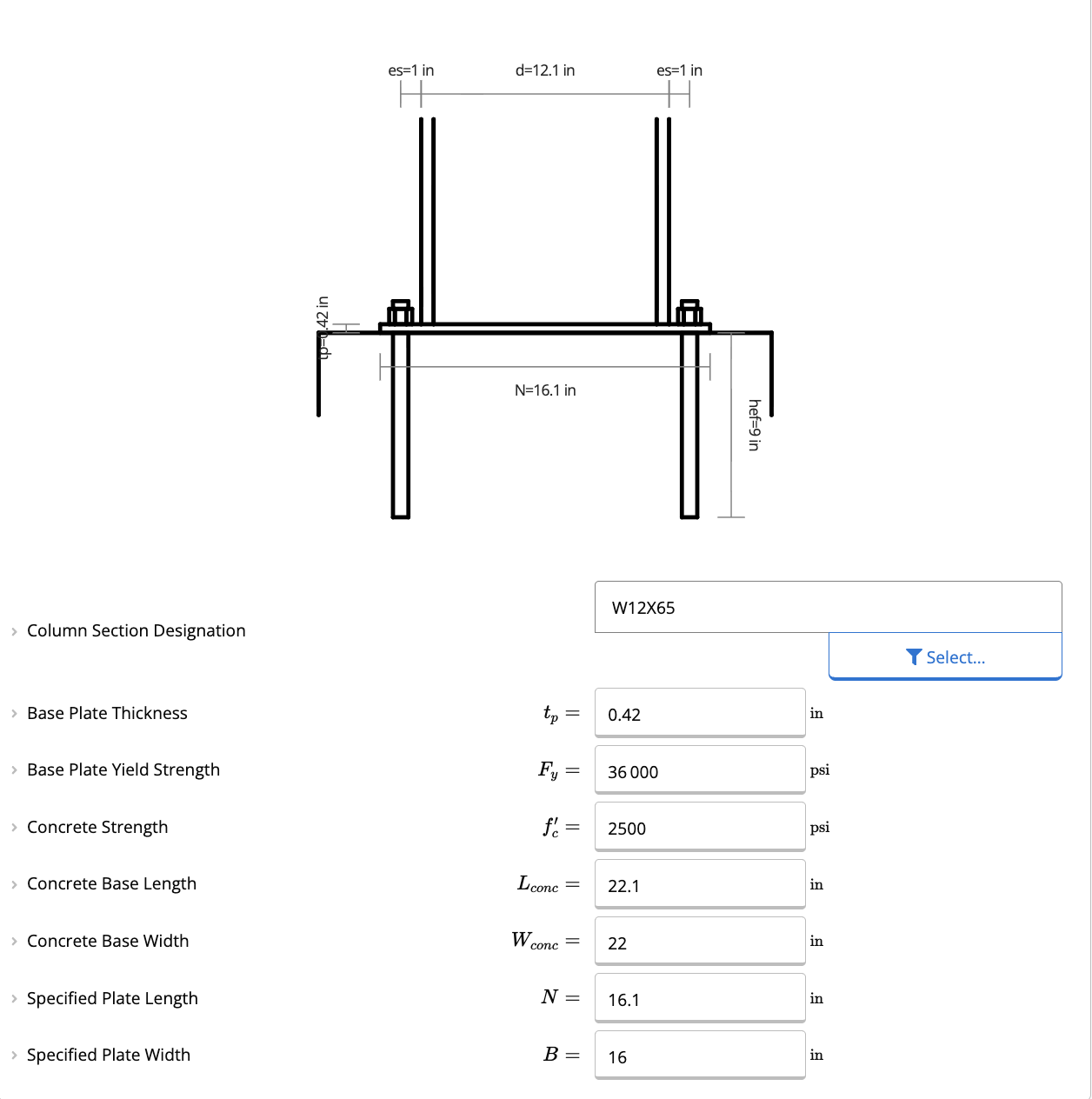
Begin by defining the geometry and material properties of your column and base plate.
* **Column Section Designation:** Select your column size from the database (W, S, M, HP, HSS, HSS-R, or PIPE sections).
* **Base Plate Dimensions:**
* **Thickness ($t_p$):** Enter your desired thickness. The calculator will check this against the required minimum thickness ($t_{min}$).
* **Yield Strength ($F_y$):** Typically 36 ksi (A36 steel), but can be adjusted.
* **Plate Length ($N$) & Width ($B$):** Define the physical dimensions of the plate.
The calculator provides **Estimated Minimum Plate Length ($N_{calc}$)** and **Width ($B_{calc}$)** based on the column dimensions and required bearing area to help you size the plate quickly.
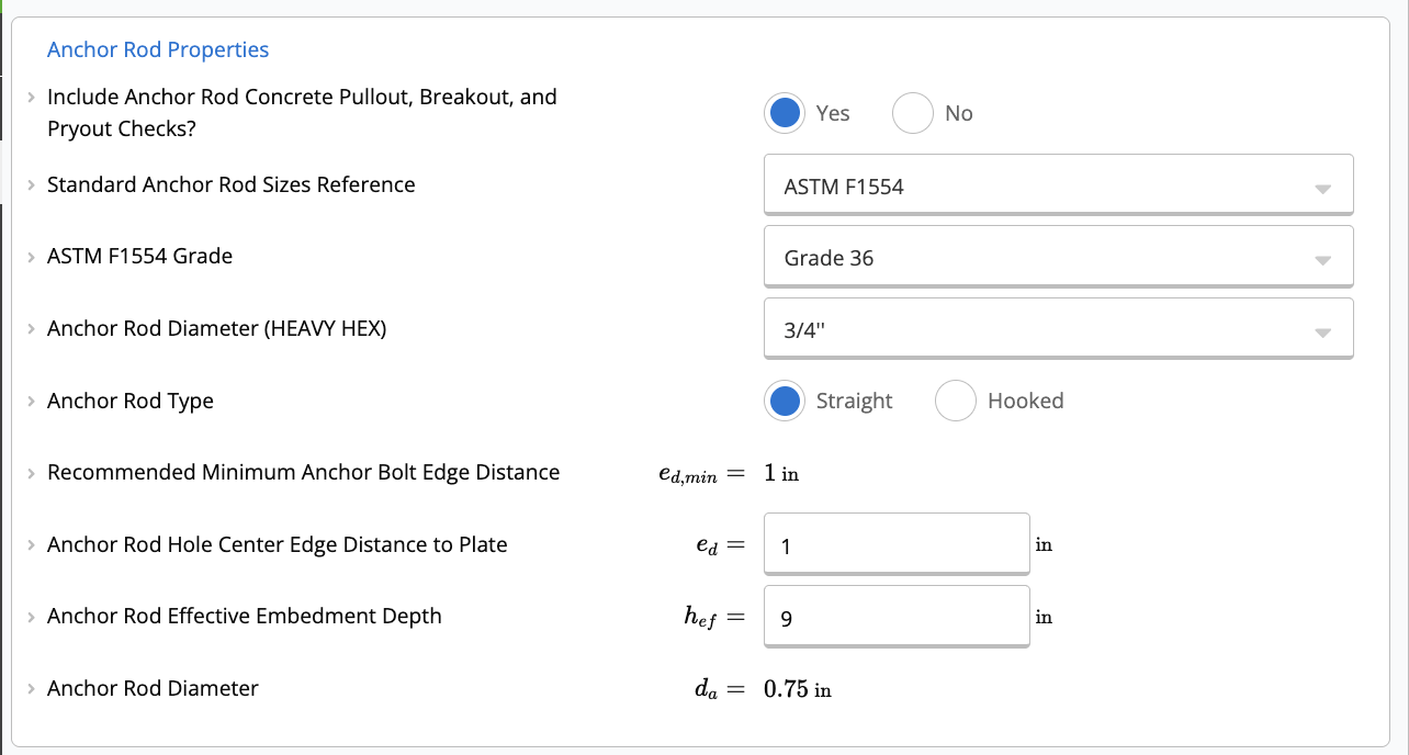
Configure the anchorage for the connection.
* **Standard Reference:** Choose between **ASTM F1554** grades (Grade 36, 55, 105) or **Custom** anchor rods.
* **Rod Diameter ($d_a$):** Select a standard diameter (e.g., 3/4") or enter a custom value.
* **Anchor Type:** Choose between **Straight** or **Hooked** rods.
* **Embedment ($h_{ef}$):** Define the effective embedment depth.
* **Edge Distance ($e_d$):** Specify the distance from the center of the anchor to the edge of the plate.
The calculator currently defaults to a 4-bolt configuration.
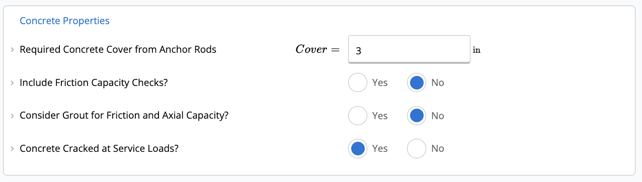
Define the supporting concrete pedestal or foundation.
* **Concrete Strength ($f'_c$):** Compressive strength of the concrete (e.g., 3000 psi).
* **Base Dimensions:** Enter the length ($L_{conc}$) and width ($W_{conc}$) of the concrete support.
* **Grout:** You can toggle whether to include a grout pad and specify its strength ($f'_{cg}$).
* **Cracked Concrete:** Specify if the concrete is assumed to be cracked at service loads (affects anchor breakout capacity).
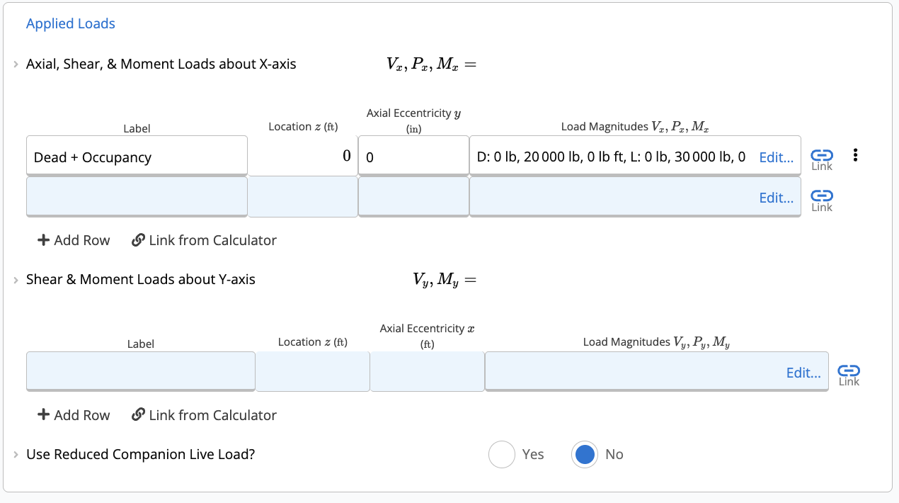
Input your unfactored loads. The calculator will automatically apply load combinations based on ASCE 7-16 (or your project defaults).
* **Axial, Shear, & Moment (X-Axis):** Enter loads acting about the X-axis (Strong axis).
* **Shear & Moment (Y-Axis):** Enter loads acting about the Y-axis (Weak axis).
Axial loads entered in the X-axis table are added to any axial loads in the Y-axis table. Do not duplicate axial loads.
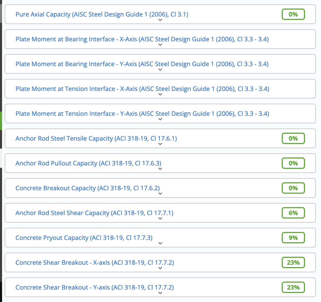
The calculator provides real-time checks for various failure modes.
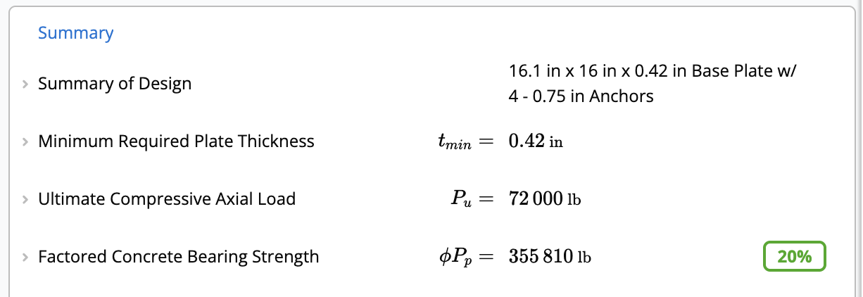
**Summary**
* **Minimum Required Plate Thickness ($t_{min}$):** The governing thickness required to satisfy bending demands from axial and moment loads.
* **Concrete Bearing Strength ($\phi P_p$):** Checks if the concrete/grout can support the compressive loads.
**Anchor Capacity**
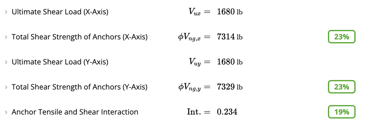
If **Include Anchor Rod Concrete Pullout, Breakout, and Pryout Checks?** is set to **Yes**, the following are checked using factored (LRFD) loads:
* **Total Tensile Capacity of Anchors:** Checks steel strength, concrete breakout, and side-face blowout.
* **Total Shear Strength of Anchors:** Checks steel shear strength, concrete breakout, and pryout strength in both X and Y directions.
* **Anchor Tensile and Shear Interaction:** Checks combined tension and shear interaction (must be $\le 1.2$).
**Detailed Checks**
Want to dig deeper? Scroll down to the detailed sections to see exactly how each capacity is calculated.
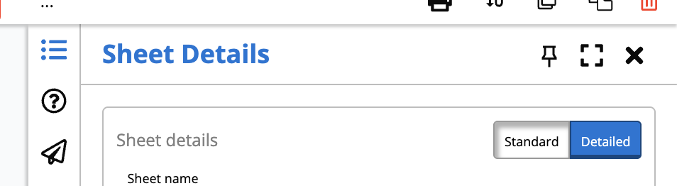
**Pro Tip:** Ensure your view is set to **"Detailed"** using the toggle at the top of the calculator. This reveals all intermediate steps and formulas used in the calculations.
* **Plate Bending ($M_{u,pl}$):** Verifies the plate's capacity against the ultimate moment demand at the bearing interface.
* **Concrete Breakout ($A_{Nc}, A_{Vc}$):** Reviews the projected failure areas and specific modification factors ($\Psi$) used for edge distance, eccentricity, and cracking.
* **Frictional Shear ($\phi V_f$):** If enabled, calculates the shear capacity provided by friction between the base plate and concrete.
Watch this video for an overview of the Steel Base Plate calculator and learn how to efficiently design steel base plates and anchor rods:
The Calcs.com Steel Base Plate calculator enables a fast and efficient design of steel base plates and anchor rods using LRFD (Load and Resistance Factor Design) methodology. The calculator provides the required base plate thickness and anchor capacities based on compressive axial capacity, flexural design, and anchor design. This calculator follows ACI 318-19, which exclusively uses Strength Design for concrete anchorage.
This calculator performs calculations per **ACI 318-19**, **AISC 360-16**, and the **AISC Design Guide 1, 2nd Edition**.
**Want to learn more?** Check out our [Steel Base Plate Design webinar](https://calcs.com/webinars/steel-base-plate-design) for an in-depth walkthrough of base plate design, including design considerations, failure modes, and worked examples using this calculator.
## Common questions
The calculator follows AISC Design Guide 1, 3rd Edition (2024) for base plate sizing and plate bending, and ACI 318-19 Chapter 17 for anchor rod capacities. It uses AISC 360-22 for steel member properties and ASCE 7-22 Chapter 2 for load combination generation.
Inputs include the column section, base plate dimensions and material grade, anchor rod diameter, grade, and embedment depth, concrete edge distances and spacings, concrete compressive strength f'c, and unfactored column loads (axial, biaxial moments, and biaxial shear). The seismic design category can be selected to invoke ACI 318-19 seismic anchor provisions.
The calculator checks: concrete bearing strength per AISC DG1 3rd ed., plate bending at bearing and tension interfaces in both axes, anchor rod steel tensile and shear capacity (ACI 318-19 Cl 17.6.1 and 17.7.1), concrete breakout in tension and shear, pullout, side-face blowout, concrete pryout, and frictional shear capacity under the plate.
Yes. The calculator resolves biaxial moments with the factored axial load to determine the bearing pressure distribution and anchor tension demand. It applies the AISC Design Guide 1 (3rd ed.) procedure for both the small-moment (full contact) and large-moment (partial contact with uplift) regimes across both plate axes.
Any concrete compressive strength f'c can be entered. Anchor rods are specified by ASTM designation (F1554 Gr. 36, 55, 105 or equivalent), diameter, and embedment depth. The seismic toggle applies the ACI 318-19 Chapter 17 seismic requirements for anchors in higher seismic design categories.
Yes, the base plate calculation receives axial and shear loads from the column calculation above. When the column size or loading changes, the base plate demand updates automatically. This load-linking removes the need to manually transfer forces between calculations.
## Next steps
Analyze steel bolt groups under eccentric in-plane shear and moment to the AISC Steel Construction Manual, 15th and 16th edition (ASD), using the elastic...
 **Anchor Capacity**
If **Include Anchor Rod Concrete Pullout, Breakout, and Pryout Checks?** is set to **Yes**, the following are checked using factored (LRFD) loads:
* **Total Tensile Capacity of Anchors:** Checks steel strength, concrete breakout, and side-face blowout.
* **Total Shear Strength of Anchors:** Checks steel shear strength, concrete breakout, and pryout strength in both X and Y directions.
* **Anchor Tensile and Shear Interaction:** Checks combined tension and shear interaction (must be $\le 1.2$).
**Anchor Capacity**
If **Include Anchor Rod Concrete Pullout, Breakout, and Pryout Checks?** is set to **Yes**, the following are checked using factored (LRFD) loads:
* **Total Tensile Capacity of Anchors:** Checks steel strength, concrete breakout, and side-face blowout.
* **Total Shear Strength of Anchors:** Checks steel shear strength, concrete breakout, and pryout strength in both X and Y directions.
* **Anchor Tensile and Shear Interaction:** Checks combined tension and shear interaction (must be $\le 1.2$).
 **Detailed Checks**
Want to dig deeper? Scroll down to the detailed sections to see exactly how each capacity is calculated.
**Detailed Checks**
Want to dig deeper? Scroll down to the detailed sections to see exactly how each capacity is calculated.
 * **Plate Bending ($M_{u,pl}$):** Verifies the plate's capacity against the ultimate moment demand at the bearing interface.
* **Concrete Breakout ($A_{Nc}, A_{Vc}$):** Reviews the projected failure areas and specific modification factors ($\Psi$) used for edge distance, eccentricity, and cracking.
* **Frictional Shear ($\phi V_f$):** If enabled, calculates the shear capacity provided by friction between the base plate and concrete.
* **Plate Bending ($M_{u,pl}$):** Verifies the plate's capacity against the ultimate moment demand at the bearing interface.
* **Concrete Breakout ($A_{Nc}, A_{Vc}$):** Reviews the projected failure areas and specific modification factors ($\Psi$) used for edge distance, eccentricity, and cracking.
* **Frictional Shear ($\phi V_f$):** If enabled, calculates the shear capacity provided by friction between the base plate and concrete.