

CanadaCSA O86:19NBCC 2015CWC Wood Design Manual 2017

The easy to use online Calcs.com Wood Beam Calculator to CSA O86:19 enables you to do quick and powerful design and analysis for simple and continuous timber beams, with unlimited supports and loads. Choose from our library of thousands of common wood sections, or create your own and get instant results with our easy to understand traffic light checks for moment, deflection, and shear.
The Calcs.com Wood Beam - Generic Beam, Joist, and Girder Calculators allow you to quickly design wood horizontal members. In this article, each section of the calculator will be explained followed by a worked example.
The Wood Beam Calculator has 4 main sections
- Key Properties
- Loads
- Design Conditions
- Summary and Graphs
Worked example
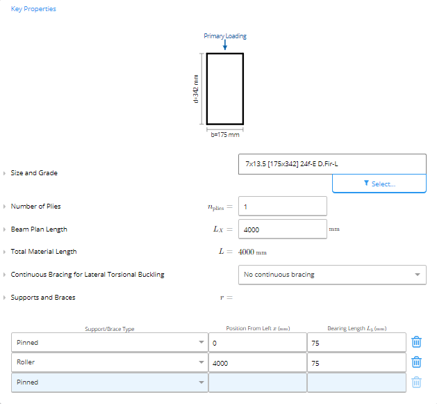
Design a wood beam with the following characteristics:* Length: 4 meters
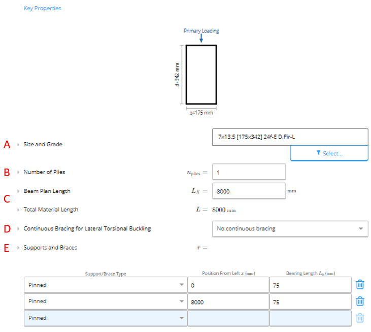
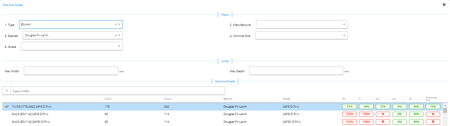
- Member type: Glulam, Douglas Fir
- Supports: Pinned and roller support on the left and right respectively, 75 mm bearing length
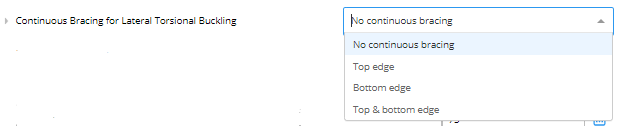
- Bracing: No continuous bracing
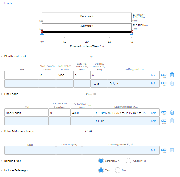
- Loads: 10 kN/m dead load and 15 kN/m live loads along the strong axis
- Self-weight included
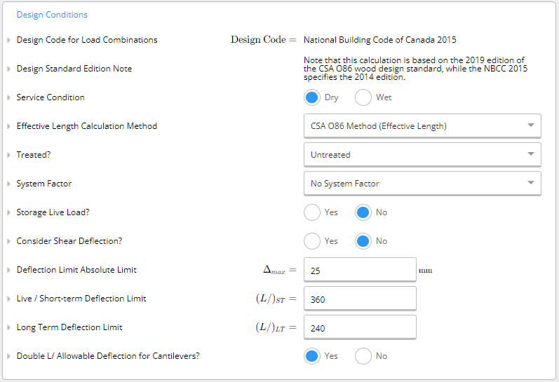
- Dry service conditions, untreated with no load sharing
Key Properties Input
Load Input
Design Conditions Input
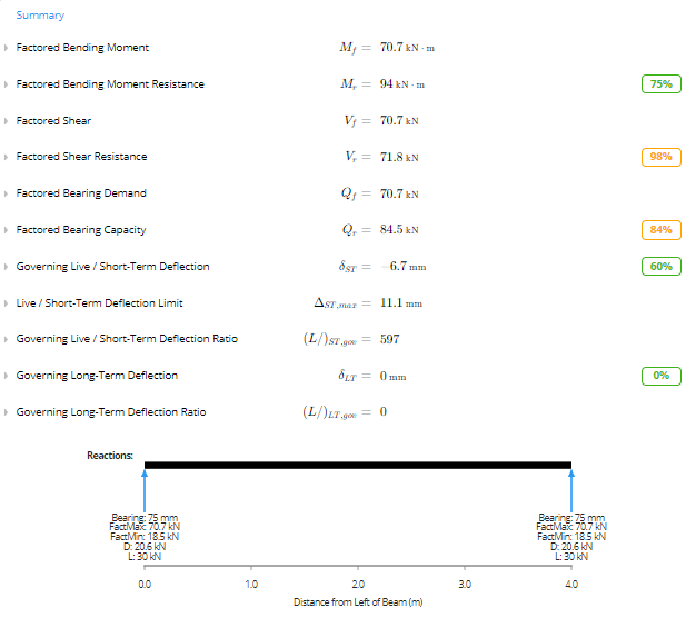
Summary and Graphs
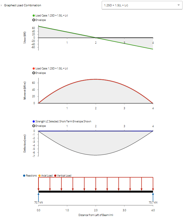
Access the full PDF file here: [CA] Wood Beam Example
Method & scope
See the exact clause
Calculation method
Structural model and load combinations
The calculator models the beam as a one-dimensional element and computes bending moment, shear, and deflection diagrams under each NBCC 2015 load combination. Loads are entered by type, dead (D), live (L), snow (S), wind (W), and the calculator automatically generates all governing strength (ULS) and serviceability (SLS) combinations, for example:- 1.25D + 1.5L
- 1.25D + 1.5S + 1.0L
- 0.9D + 1.5W (uplift check)
Bending moment resistance (CSA O86:19 Cl.7)
Factored bending resistance M_r is computed from the reference bending strength F_b adjusted by a chain of CSA O86:19 factors:- K_H, system factor for repetitive-member assemblies
- K_Scs, service-condition factor for bending
- K_T, treatment factor
- K_zbg, size factor for sawn lumber, or volume factor for glulam members
Shear resistance (CSA O86:19 Cl.6.5.4.3)
Factored shear resistance V_r applies the service-condition, treatment, and size adjustment factors to the reference shear strength F_v. For glulam members the calculator uses the CSA O86 simplified shear strength method, which is valid for members with volume under 2 m³. Shear demand is taken at the location of peak shear, which may conservatively be directly over the support rather than at distance d. shear utilization = V_f / V_r ≤ 1.0Bearing capacity
For each support, factored bearing demand Q_f is checked against factored bearing resistance Q_r, adjusted for service condition and treatment. A bearing contact area is specified per support; the check is skipped for supports with zero contact area.Deflection checks (CSA O86:19 Cl.5.4.2 / NBCC Commentary D)
Three independent deflection limits are verified per span:- Live/short-term deflection, governed by short-term serviceability load combinations; checked against a user-defined span/n ratio
- Long-term deflection, accounts for creep under sustained loads using the adjusted long-term modulus; checked against a separate span/n ratio
- Simplified DL+LL deflection, total dead-plus-live deflection checked against a third span/n limit
Load linking
Support reactions are exported as linked outputs. When this beam is part of a larger project, connected column and footing calculations downstream automatically receive updated reactions whenever the beam inputs change, no manual re-entry of loads required.How to use it
1
Key Properties
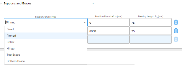
2
Loads
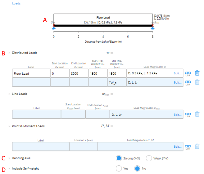
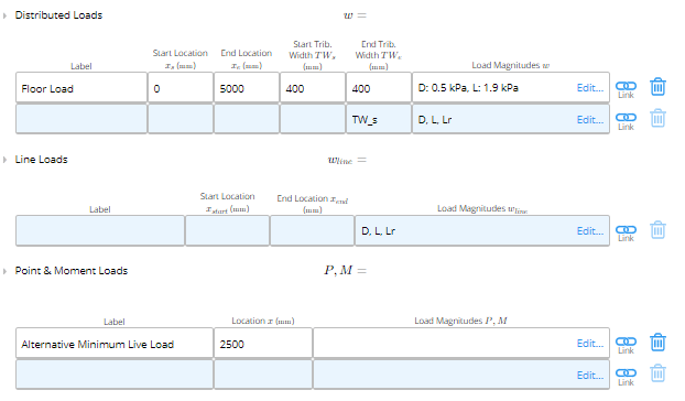
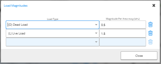
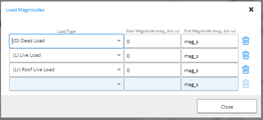
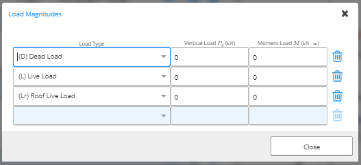
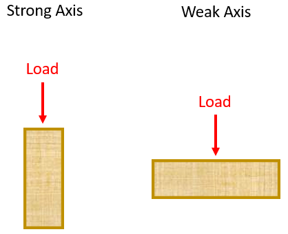
3
Design Conditions
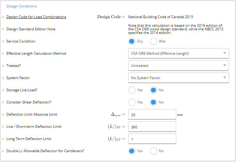
- Service Condition: You need to indicate if the service condition is ‘dry’ or ‘wet.’ It is considered wet if the moisture content of wood will exceed 19% for an extended time. Typically, wet conditions apply to most exterior uses.
- Effective Length Calculation Method: By default, Calcs.com uses the effective length calculation outlined by CSA O86:19, however, we conservatively take the effective length as 1.92L regardless of the loading condition. For a more accurate calculation, Calcs.com also provides you with the option to use the quarter-moment method outlined by the American Wood Council Technical Report 14.
- Treatment: Calcs.com requires you to indicate if the wood beam is untreated, or if it is preservative-treated and whether it is incised (partially cut) or unincised.
- System Factor: A system factor is considered if the member is part of a system where loads can be shared. There are three options for sawn lumber:
-
- No System Factor: There are less than 3 beams spaced 610 mm apart and/or are not mutually sharing loads
- Case 1 (for systems that don’t meet Case 2 requirements): There are more than 3 beams spaced less than 610 mm apart, mutually sharing loads
- Case 2 (typical for joists and rafters): All of the following conditions are met
- There are more than 3 beams spaced less than 610 mm apart, mutually sharing the load
- Members are sheathed with a minimum of 9.5 mm OSB, waferboard, plywood or with min. 17mm lumber with panel coverings.
- The sheathing is attached with sufficient stiffness and adequate spacing equal to 2 common nails at 150 mm on center at edges and 300 mm on center elsewhere.
- For glulams and LVL’s the option is simply whether to consider a system factor or not - generally it can be considered if more than three parallel members are sharing load.
- Storage Live Load: A storage live load is a live load (loads due to occupancy use) that occurs for a long duration. An example of this is storage in an attic. If this is set to yes, the duration factor associated with live load will be taken the same as dead load, and the load factor on live load will be increased in some combinations.
- Consider Shear Deflection: Shear deflection can be a significant component of total deflection due to the low shear modulus. In particular, specifications for structural composites such as LVL often require that shear deflection be directly accounted for. If this is set to “Yes”, we use an approximation based on the peak moment within a span to find the shear deflection. This gives exact results for simply supported and cantilever spans with either a point load in the center or a UDL.
- Absolute Deflection Limit: The maximum allowable deflection for the beam in millimeters (mm) or inches (in).
- Live/Short-term Deflection Ratio: The maximum allowable deflection ratio for live and short loading. The default is L/360 but you may change this to a preferred ratio.
- Long Term Deflection Ratio: The maximum allowable deflection ratio for long-term loading. The default is L/240 but you may change this to a preferred ratio.
- Double Length/Allowable Deflection for Cantilevers: For cantilever spans, it’s typical to take “L” as double the span length. To adjust for this, the allowable deflection can be doubled.
4
Summary and Graphs
In the summary section, the key parameters of your calculation will be outlined. In the graphs section, you can select the load combination you would like the see in the graphs.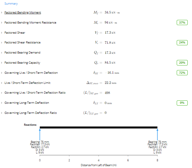
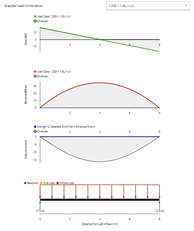
- Load Combination Analysis
- Unfactored Load Combination Analysis
- Modulus of Elasticity (CSA O86:19 Section 6.3)
- Bending Moment Resistance (CSA O86:19 Section 6.5.3)
- Positive Bending (CSA O86:19 Section 6.5.3)
- Negative Bending (CSA O86:19 Section 6.5.3)
- Shear Resistance (CSA O86:19 Section 6.5.4)
- Bearing (Compressive Resistance Perpendicular to Grain) (CSA O86:19 Section 6.5.6)
- Deflections
Available presets
Each preset opens the calculator with a typical setup already entered.Common questions
What design standard does this calculator use?
What design standard does this calculator use?
The calculator designs wood beams to CSA O86:19 (Limit States Design) with load combinations per NBCC 2015. Species and grade properties are drawn from the CWC Wood Design Manual 2017. Supported product types include sawn lumber, glulam, and SCL (LVL, PSL, LSL).
What are the key inputs?
What are the key inputs?
Key inputs include the wood section (species, grade, and product type from the built-in database), beam plan length, number of plies, service condition (dry or wet), treatment, support layout, loads by type (dead, live, snow, wind), lateral top-flange bracing spacing, and three independent deflection limit ratios.
What checks and outputs does it produce?
What checks and outputs does it produce?
The calculator checks factored bending moment resistance (M_f/M_r ≤ 1.0), shear resistance (V_f/V_r ≤ 1.0), bearing capacity at each support, governing live/short-term deflection, long-term deflection, and simplified DL+LL deflection, each against user-defined span ratios and an optional absolute limit. Lateral stability (slenderness ratio ≤ 50) is verified per CSA O86:19 Cl.7.5.6.4.
Can it handle multi-ply beams and glulam?
Can it handle multi-ply beams and glulam?
Yes. Multi-ply (built-up) beams are supported in strong-axis bending with any number of plies. Glulam checks use the CSA O86 simplified shear resistance method, valid for members with volume under 2 m³, the calculator enforces this limit automatically. LVL and other SCL products from major Canadian manufacturers are included in the section database. Weak-axis bending is supported for single-ply members only.
How do I select a wood section?
How do I select a wood section?
Use the section picker to filter by product type (sawn lumber, glulam, SCL), species group, and grade. The calculator loads CSA O86:19 tabulated reference design values automatically. You can also define a custom section by entering cross-section dimensions and manually entering design values if your species or grade is not in the built-in database.
Does this calculator support load linking with column and footing calculations?
Does this calculator support load linking with column and footing calculations?
Yes, beam reactions link directly to connected column and footing calculations in the same project. When you change a span, load, or section, all downstream calculations update automatically, no manual re-entry of reactions required.
Next steps
Design a Wood Column to CSA O86
Design wood columns and studs to CSA O86:19, with load linking between beams and columns.
🇨🇦 Calculators for Canada
Complete list of Calcs.com design calculators available for Canadian projects (CSA O86, CSA S16, NBCC, and related standards).
Generalized Lateral Stability Calculation for Wood Beams
How the lateral stability factor KL for wood beams in bending is calculated to CSA O86:19, including effective lengths for common loading conditions.
Design a Sloped or Angled Member
Design rafters, hip beams and other inclined members: set the slope, choose plan or inclined view, pick a load orientation, or convert lengths with formulas.