- Key Properties
- Design Conditions
- Loads
- Summary and Graphs
1. Key Properties
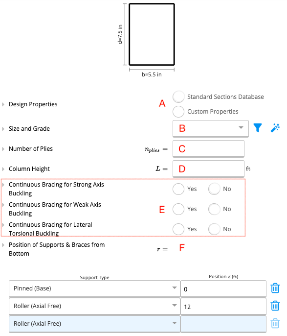
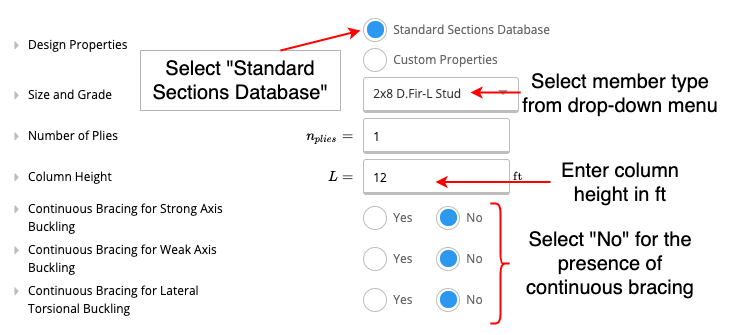
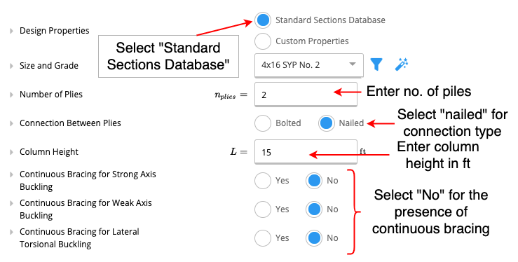
A. Design Properties
In this section, the user can select ‘Custom Properties’ if they wish to use a custom-sized member or they can choose ‘Standard Sections Database’ to access a drop-down menu with industry-standard sized members as shown in part B.B. Size & Grade
The user can select the size of the member they want to use from a list of industry-standard sized members.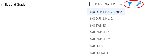
C. Number of Plies
The number of timber laminates in the column. This quantity needs to be either equal to or greater than 1.D. Column Height
The total height of the column needs to be given in feet (ft).E. Lateral Restraint Conditions
The user is prompted to specify whether or not the following exists for the column that is being designed.- Continuous bracing for strong (major) axis buckling
- Continuous bracing for weak (minor) axis buckling
- Continuous bracing for lateral-torsional buckling
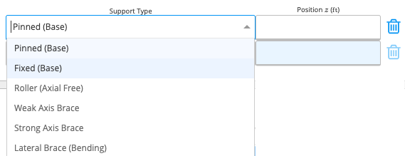
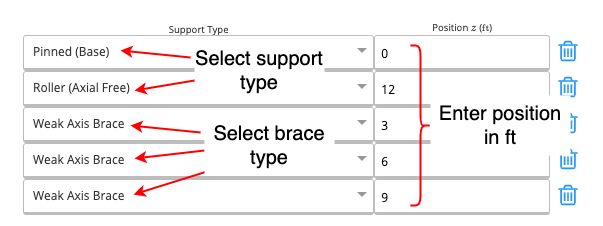
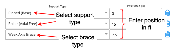
F. Position of Supports and Braces From Bottom
2. Design Conditions
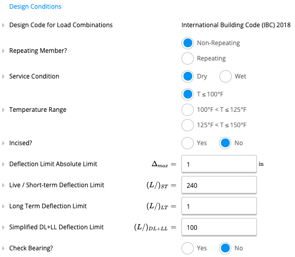
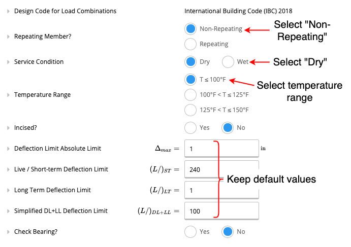
- Repeating Member: A member is considered repeating if multiple members are repeating at less than 24” spacing under a load-distributing element, such as a floor or roof.
- Service Condition: The user can select if the service condition is ‘dry’ or ‘wet.’ It is considered wet if the moisture content of wood will exceed 19% for an extended time. Most often applies only to exterior use.
- Temperature Range: The user can specify the range of sustained temperature exposure from the options given.
- Incised: A member is incised if lumber is incised to a maximum depth of 0.4” and a maximum length of 3/8”, with a density of incision up to 1100/ft².
- Deflection Limit Absolute Limit: This is the hard maximum deflection allowed for the beam, regardless of span length. Normally, the local building code will dictate this. This quantity must be specified in inches(in).
- Check Bearing: If this is set to yes, a bearing check will be performed assuming the column bears on a perpendicular member of the same material and grade.
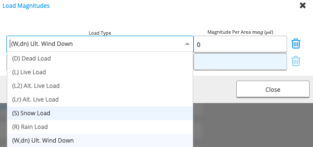
3. Loads
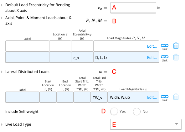
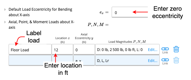
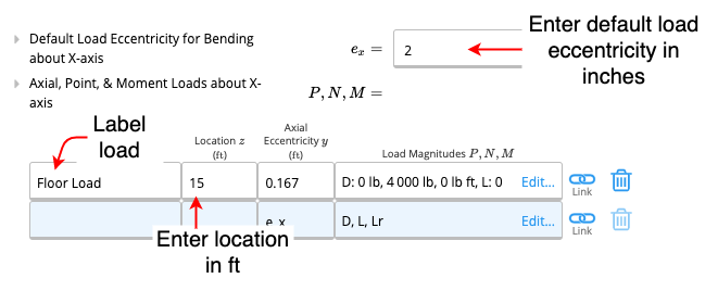
A. Default Load Eccentricity for Bending About X-axis
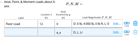
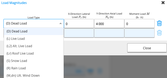
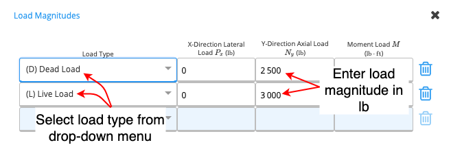
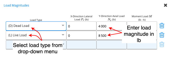
What is Load Eccentricity? Generally, axial loads (i.e. loads acting vertically downwards) act through the centre of a column. However, in some cases, the load can act off the centre of the column and cause bending in addition to compression of the column. Axial load eccentricity refers to the horizontal distance between the centre of the column and the line of action of the axial load. Specifying Load Eccentricity in ClearCalcs The default load eccentricity is set to zero (i.e. no bending, pure compression is assumed). If a user wishes to change this, they need to specify the new load eccentricity in inches (in).B. Axial, Point & Moment Loads About X-axis
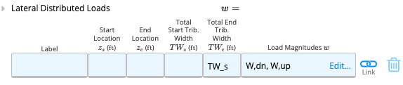
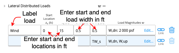
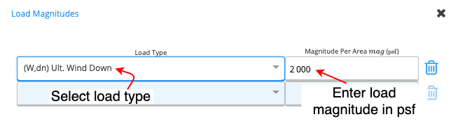
C. Lateral Distributed Loads
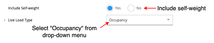
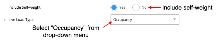
D. Include Self-Weight
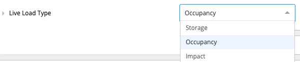
The user can choose whether or not they include the self-weight of the column in their calculations. The calculator is set to include the self-weight by default unless the user specifies otherwise.E. Live Load Type
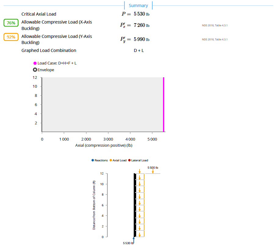
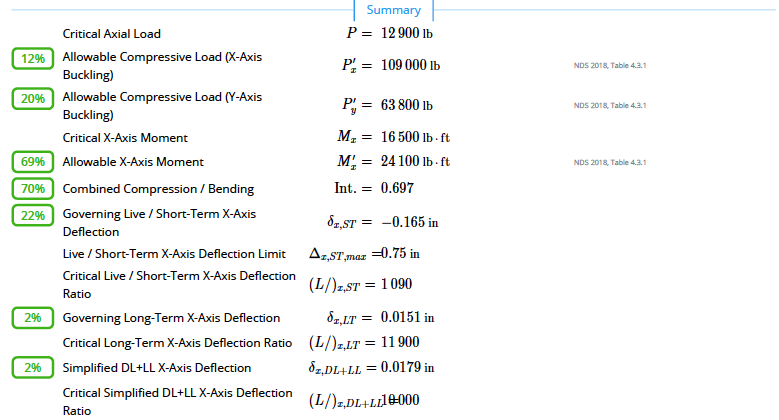
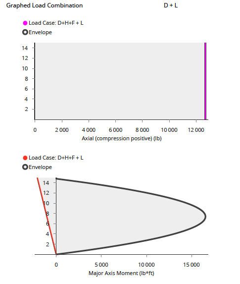
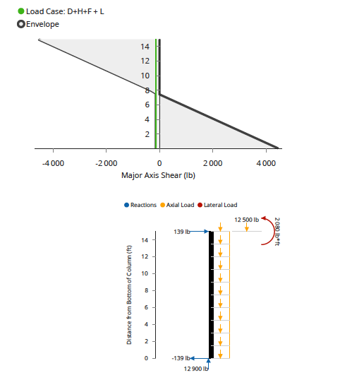
4. Summary & Graphs
The summary section the key parameters of your calculation will be outlined. In the graphs section, the user can select the load combination that they would like the see in their graph (e.g.: D+L). A sample of the summary and graphs produced during calculations can be seen in the examples given below.Examples
Task 1
Design a timber stud with the following characteristics- for residential application
- 12ft in height with noggings (along the weak axis) every 3ft
- member type: 2x8 Douglas Fir stud
- fixed base and a roller support at the top
- an axial load at the top: 1000lbs/ft dead load and 1200lbs/ft live load with 2.5ft stud spacing
- assume zero eccentricity
- include self-weight
- assume dry service conditions and temperature conditions to be <100 degrees F
Method

Task 2
Design a timber column with the following characteristics- for residential application
- 15ft in height with a weak axis brace halfway along the column
- fixed support at the bottom and roller support at the top
- 2 piles nailed together
- Assume default load eccentricity to be equal to 2 inches
- Axial load at the top: 4000lb dead load and 8500lb live load
- A laterally distributed wind load of 2000psf from top to bottom of the column (load width 0.5ft)
- include self-weight
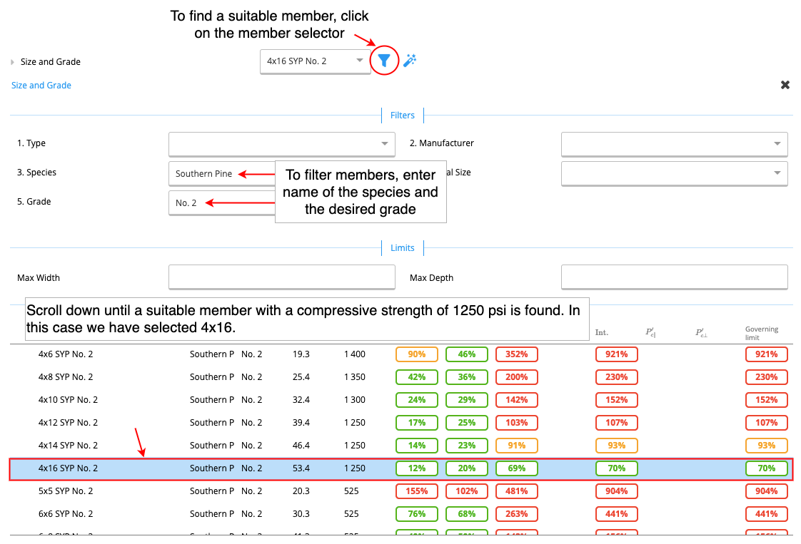
- select a No.2 grade Southern Pine Member with a compressive strength of 1250psi
- assume dry service conditions and temperature conditions to be <100 degrees F
Method
 |  |