

In the Calcs.com Beam Analysis and Wood Beam calculators, a downward load is entered as a positive number, and support reactions that push up are positive. Shear, moment and deflection are plotted along the beam: a positive moment plots above the axis, and a downward deflection is negative. In the Wood Beam calculator, the strong axis (X-X) is the axis with the higher moment of inertia. This article shows each convention with US-unit screenshots from three calculators.
Worked example
Symbols
The article uses these symbols, with the names the sheets use.Example 1: a fixed-roller beam under a uniform load
A 20 ft beam is fixed at the left end and on a roller at the right end. It carries one downward uniform load of 1 kip/ft over its full length. This one beam shows every sign in the Beam Analysis calculator: the load, the shear, a negative moment at the fixed support, a positive moment in the span, a downward deflection, and upward reactions with a moment reaction. The run is on Beam Analysis in a US customary project. The edits are:- Supports: Fixed at 0 ft and Roller at 20 ft
- Distributed Load: 1000 plf at the start and the end, from 0 ft to 20 ft (the default load is replaced)
1
Set the supports
In Position of Supports from Left, set the first support to Fixed at 0 ft and the second to Roller at 20 ft.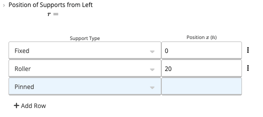
2
Enter the load
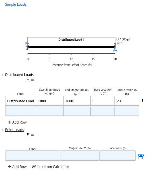
In Simple Loads, replace the default load with a Distributed Load of 1000 plf at the start and the end, from 0 ft to 20 ft. The load is entered as a positive number and the diagram draws it as an arrow pointing down.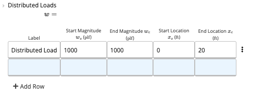
3
Read the summary and the reactions
The Summary shows a Moment Demand of −50 000 lb·ft, a Shear Demand of 12 500 lb, a Deflection of −0.0715 in, a Maximum Lateral Reaction of 12 500 lb and a Maximum Moment Reaction of 50 000 lb·ft. The reactions diagram shows 12 500 lb up at the fixed end, with a curved arrow for the moment reaction, and 7500 lb up at the roller.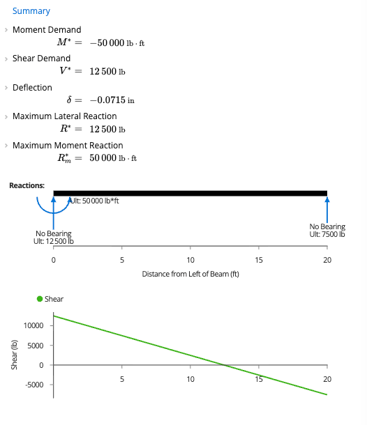
4
Read the graphs
The shear graph starts at +12 500 lb at the fixed end, crosses zero at about 12.5 ft and ends at −7500 lb. The moment graph starts at −50 000 lb·ft at the fixed end, crosses zero at 5 ft, peaks at about +28 000 lb·ft near 12.5 ft and returns to zero at the roller. The deflection graph is below the axis, lowest at about −0.07 in. In the last diagram the load arrows point down and the reaction arrows point up.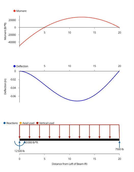
5
Check the reactions per support
Per-Support Analysis lists a reaction of 12 500 lb, a moment of −50 000 lb·ft and a shear of 12 500 lb at 0 ft, and a reaction of 7500 lb, a moment of 0 and a shear of −7500 lb at 20 ft. The moment and shear columns match the moment and shear graphs at each support.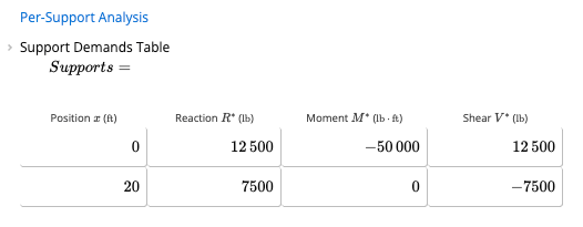
Inputs, Calcs.com output and a hand check
Inputs
CalculatorBeam Analysis
Span 20 ft
SupportsFixed at 0 ft, Roller at 20 ft
Uniform load 1000 plf, downward
Calcs.com output
Reaction at the fixed end12 500 lb up
Moment at the fixed end−50 000 lb·ft
Reaction at the roller7500 lb up
Peak span momentabout +28 000 lb·ft
Deflection−0.0715 in
Hand check
✓Total load: lb
✓Roller reaction: 7500 lb
✓Fixed-end reaction: 12 500 lb
✓Fixed-end moment: 50 000 lb·ft, negative because it is a hogging moment
✓Peak span moment: 28 125 lb·ft
The reactions, the end moment and the peak span moment match the closed-form solution for a beam fixed at one end and simply supported at the other. This is a sanity check only. The deflection depends on the section and is not hand-checked. Beam Analysis.
Loads
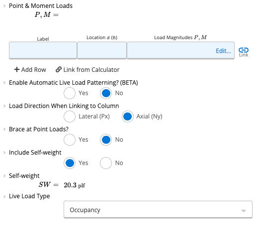
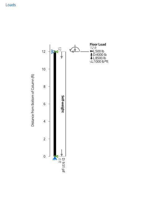
A vertical load is entered as a positive number when it acts downward, and the load diagrams draw it as an arrow pointing down. This is the same in Beam Analysis, in the Wood Beam calculator and for the axial load on a column. The Wood Beam Loads panel draws a floor load and the self-weight as arrows pointing down.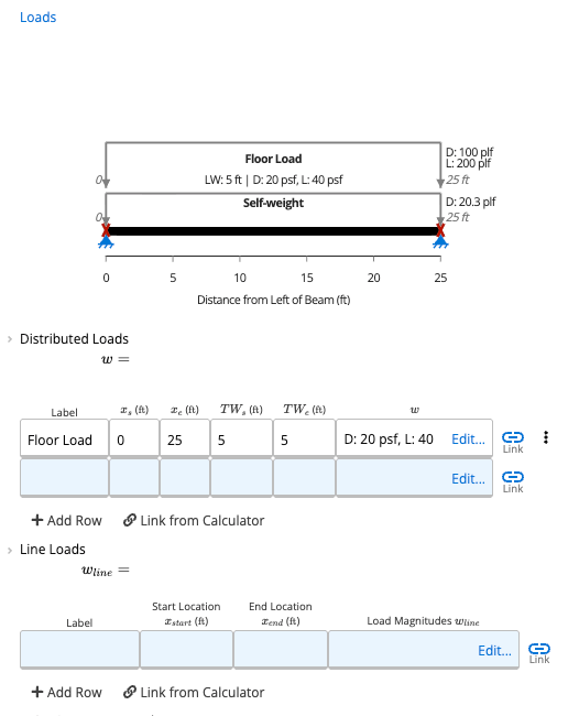
Shear, moment and deflection
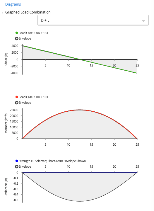
The shear, moment and deflection graphs follow the same rules in Beam Analysis (below the Summary) and in the Diagrams panel of the Wood Beam calculator.- Shear: under a downward load the shear is positive at the left support and negative at the right.
- Moment: a positive (sagging) moment plots above the axis, and a negative (hogging) moment plots below it. In Example 1, the fixed support gives a negative moment at that end.
- Deflection: a downward deflection is negative and plots below the axis.
Reactions
Support reactions that push up on the beam are positive. In Beam Analysis, the reactions diagram draws them as arrows pointing up, and for a fixed support it also draws the moment reaction as a curved arrow. In Example 1 the curved arrow reads counter-clockwise at the fixed end. When a reaction is linked to another calculator, the value is carried through as it appears in the reaction table, with no sign change. See Linking loads and reactions between calculators.Strong and weak axis
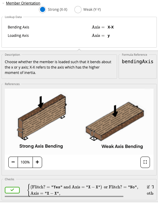
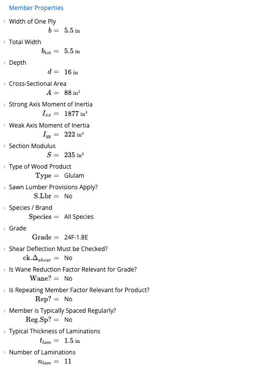
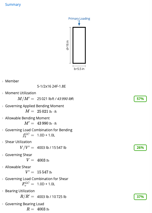
In the Wood Beam calculator, Member Orientation in Design Conditions chooses whether the member bends about the strong axis (X-X) or the weak axis (Y-Y). X-X is the axis with the higher moment of inertia. For the 5-1/2x16 24F-1.8E member in the Wood Beam screenshots, the strong axis moment of inertia is 1877 in⁴ and the weak axis is 222 in⁴.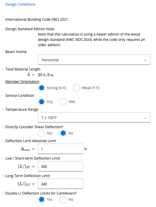
Column loads and bracing
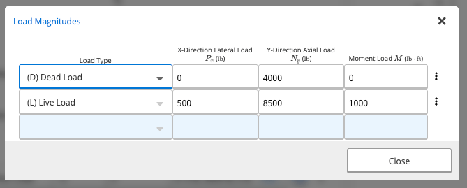
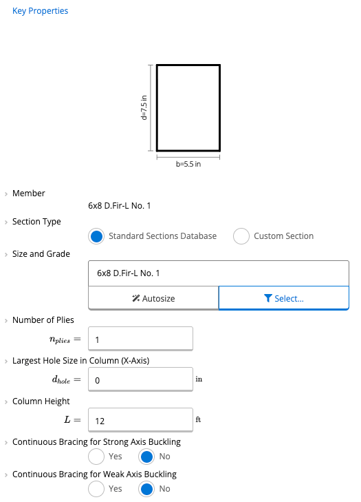
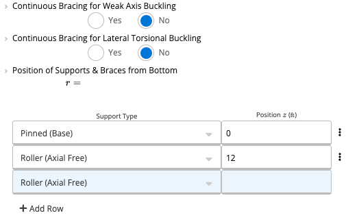
The Wood Column calculator measures positions up from the bottom of the column, and the diagram is labeled Distance from Bottom of Column (ft). Column loads are listed in the Axial, Lateral & Moment Loads table and entered in the Load Magnitudes window, opened with Edit… on a load row.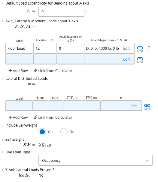
Common questions
Why is my deflection negative?
Why is my deflection negative?
A downward deflection is negative in the Summary and plots below the axis. In Example 1 the load acts downward and the deflection is −0.0715 in.
Why is the moment negative at a fixed support?
Why is the moment negative at a fixed support?
A fixed support under a downward load gives a hogging moment, which plots below the axis as a negative value. In Example 1 the moment at the fixed end is −50 000 lb·ft, and the moment in the span is positive.
Which axis is the strong axis?
Which axis is the strong axis?
In the Wood Beam calculator, the strong axis is X-X, the axis with the higher moment of inertia, and the weak axis is Y-Y. You choose between them with Member Orientation in Design Conditions.
Which way does a positive lateral load or moment point on a column?
Which way does a positive lateral load or moment point on a column?
On the Wood Column loads diagram, a positive lateral load is drawn as an arrow pointing left and a positive moment as a counter-clockwise curved arrow. Axial loads are drawn pointing down.
Next steps
Beam Analysis
Get bending moment, shear force and deflection along single or multi-span beams using linear-elastic FEA. Handles cantilevers, continuous spans and mixed loads.
Design a Wood Beam (ASD) to NDS 2024
Design wood beams to NDS 2024 (ASD): bending, shear, bearing and three deflection limits, with multi-ply and flitch plate options.
Design a Wood Column (ASD) to NDS 2024
Design wood columns and studs to NDS 2024 (ASD), with load linking from beams and a database of US wood sections.