AustraliaAS 3600:2018 (Amdt 2)

Concrete Beam

Run the calc
Beam reactions link to connected column and footing calculations automatically. Design concrete beams to AS 3600:2018 (Amdt 2) with unlimited spans. The section is rectangular by default, and a T-beam is available. Checks cover flexure, shear, deflection and lateral stability.
The calculator designs multi-span, multi-load concrete beams to AS 3600:2018. The section is rectangular by default. Type of Beam can be set to T-Beam.

Worked example

Example 1: simply supported beam

A simply supported reinforced concrete beam spans 3500 mm as an office building floor beam. The steps below follow the first example in the video underneath, with the same conditions. Example Beam 1, simply supported: a beam of 3500 mm span on two supports under a permanent load G of 0.9 kPa and an imposed load Q of 1.5 kPa, with a cross-section 300 mm deep and 130 mm wide reinforced with three N12 bars at the bottom, 50 mm from the bottom face. Conditions listed: office building floor beam, no transverse shear reinforcement, load width of 1000 mm and f′c = 32 MPa. The conditions are:
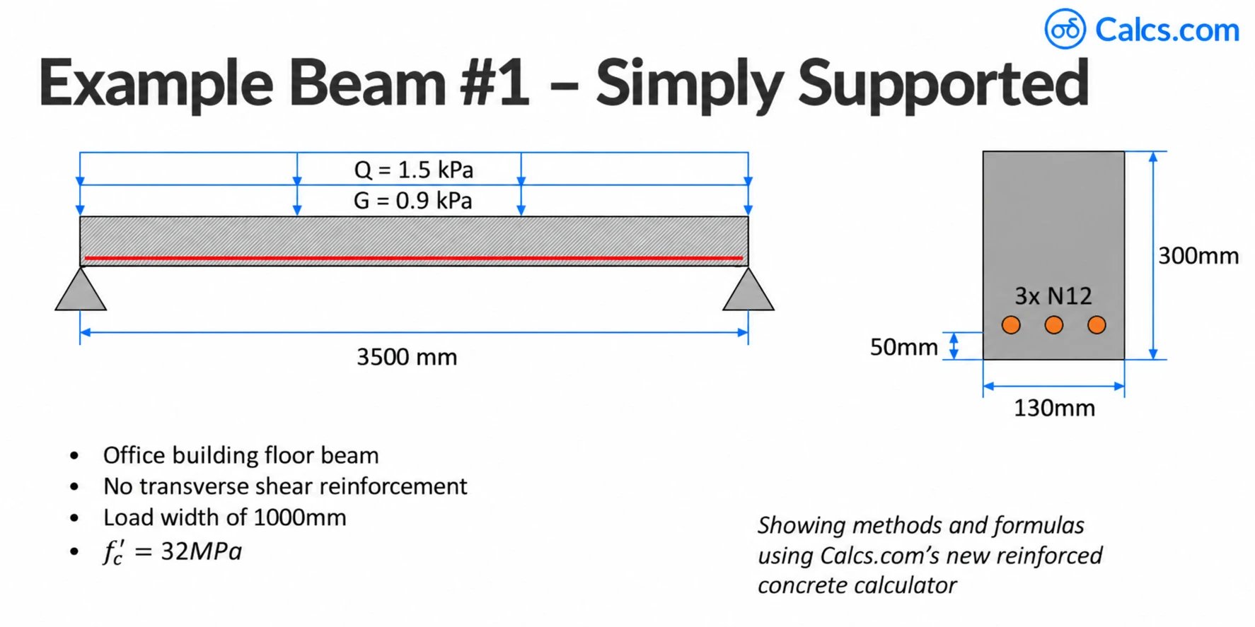
  • Span of 3500 mm, simply supported.
  • Permanent load G of 0.9 kPa and imposed load Q of 1.5 kPa, on a 1000 mm load width.
  • Office building floor beam.
  • Section 300 mm deep and 130 mm wide, with three N12 bars at the bottom and no top reinforcement.
  • No transverse shear reinforcement.
  • Concrete strength fc′f'_c = 32 MPa.
1

Open the Generic Indoor Beam preset

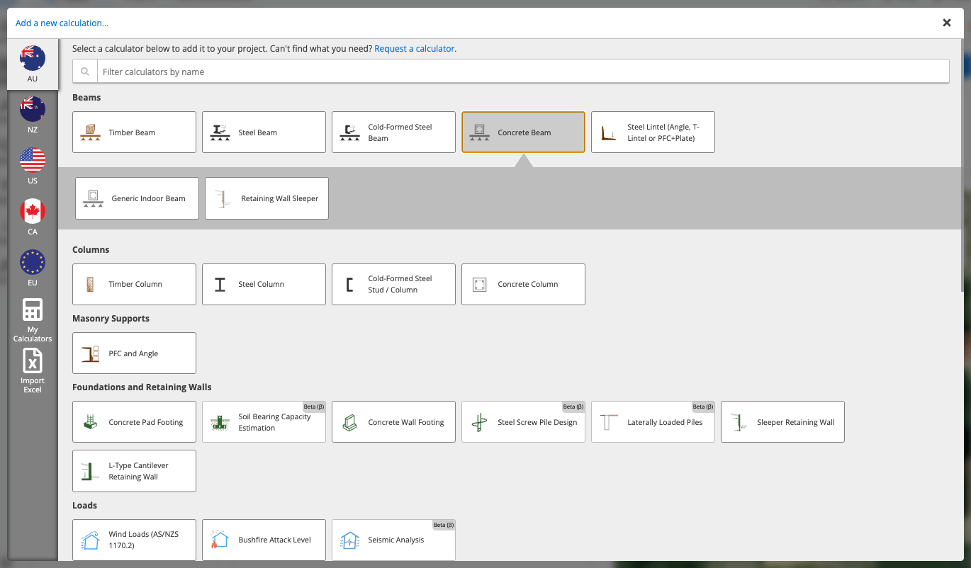
In your project, choose Add New Calculation, select Concrete Beam under Beams, then choose Generic Indoor Beam.Add a new calculation window with Concrete Beam selected under Beams and its two presets listed below, Generic Indoor Beam and Retaining Wall Sleeper.
2

Set the section size

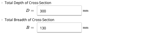
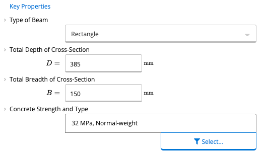
Enter 300 mm for the Total Depth of Cross-Section (D) and 130 mm for the Total Breadth of Cross-Section (B).Total Depth of Cross-Section field showing 300 millimeters and Total Breadth of Cross-Section field showing 130 millimeters.
3

Check the concrete

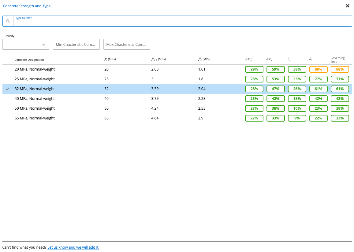
Concrete Strength and Type already shows 32 MPa, Normal-weight, so leave it as it is.Concrete Strength and Type box showing 32 MPa, Normal-weight, with its Select button.
4

Set the length and the supports

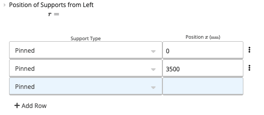
Enter 3500 mm for Total Length of Member. In the Position of Supports from Left table, the two supports are Pinned, at 0 mm and 3500 mm, so the beam is simply supported.Total Length of Member field showing 3500 millimeters.Position of Supports from Left table with two pinned supports at positions 0 mm and 3500 mm and an Add Row button.
5

Choose the bottom bars

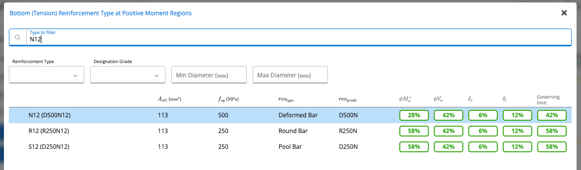
Under Bottom (Tension) Reinforcement Type at Positive Moment Regions, choose Select…, type N12 in the filter, and choose N12 (D500N12).Bottom reinforcement type window filtered to N12, listing N12 (D500N12), R12 (R250N12) and S12 (D250N12) with their bar area, yield strength, reinforcement type, grade and check badges, with N12 (D500N12) highlighted.Bottom (Tension) Reinforcement Type at Positive Moment Regions box showing N12 (D500N12), with its Select button.
6

Enter the number of bars and the cover
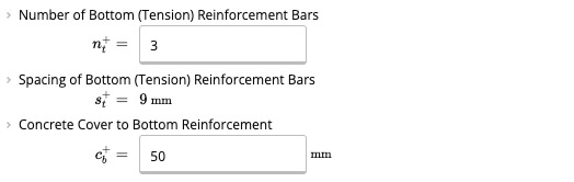
Enter 3 for the Number of Bottom (Tension) Reinforcement Bars and 50 mm for the Concrete Cover to Bottom Reinforcement. Cover is the distance from the bottom concrete surface to the bottom of the bars, so 50 mm is the dimension on the slide. With a 300 mm depth and N12 bars, the depth to the bar centre is 244 mm.The calculator shows the bar spacing, centre to centre. For three N12 bars in this 130 mm width it is 9 mm, which is less than the 12 mm bar diameter, so the bars overlap. The spacing check only requires the spacing to be at most 300 mm, so the check still passes. Whether the bars fit is a detailing check, and the sheet does not do that check.Number of Bottom Reinforcement Bars set to 3, Spacing of Bottom Reinforcement Bars shown by the calculator, and Concrete Cover to Bottom Reinforcement set to 50 millimeters.
7

Remove the top reinforcement

Set Top (Compression) Reinforcement Present to No.Top (Compression) Reinforcement Present choice set to No, with the Total Area of Top Steel shown as zero.
8

Check the shear reinforcement

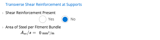
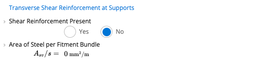
Shear Reinforcement Present is already No.Transverse Shear Reinforcement at Supports section with Shear Reinforcement Present set to No and the Area of Steel per Fitment Bundle shown as zero.
9

Check the floor load

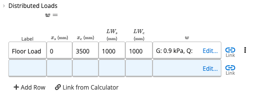
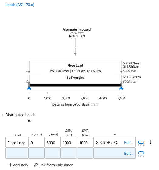
The Floor Load row in the Distributed Loads table already runs from 0 to 3500 mm on a 1000 mm load width, with G 0.9 kPa and Q 1.5 kPa.Distributed Loads table with a Floor Load row from 0 to 3500 millimeters with a load width of 1000 millimeters at both ends, and the Add Row and Link from Calculator buttons.
10

Remove the alternate imposed load

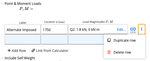
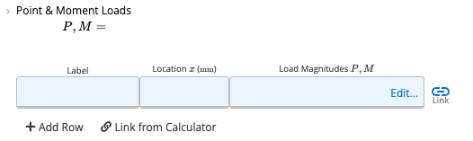
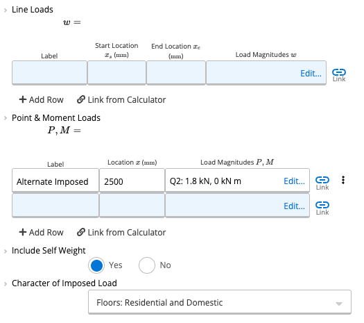
The preset adds one extra load, the Alternate Imposed point load at midspan. That is the row the video removes when it refers to wind and some other loads. The sheet has no wind load. Select the menu on the right of the row, then Delete row.Point & Moment Loads table with the Alternate Imposed row menu open, offering Duplicate row and Delete row.Point & Moment Loads table with no rows, showing the empty row with Edit and Link buttons.
11

Set the character of imposed load

Include Self Weight stays Yes. Choose Floors: Offices for the Character of Imposed Load.Character of Imposed Load dropdown set to Floors: Offices.
12

Read the results

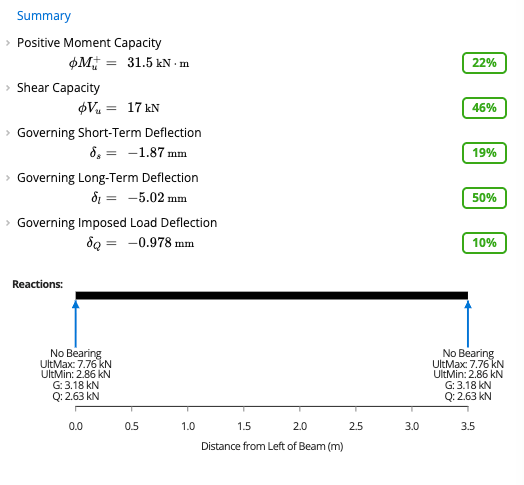
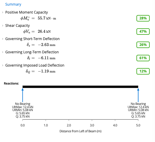
The Summary lists the positive moment capacity, the shear capacity and the three deflections, each with a utilization badge, and the Reactions diagram shows the reaction at each support. The badges at the top of the sheet show the positive moment, shear, short-term deflection and governing checks.Summary section listing the positive moment capacity, the shear capacity and the three governing deflections, each with a utilization badge, above a Reactions diagram of the beam on two supports.Badges at the top of the sheet for the positive moment, shear, short-term deflection and governing checks.
13

Look at the graphs

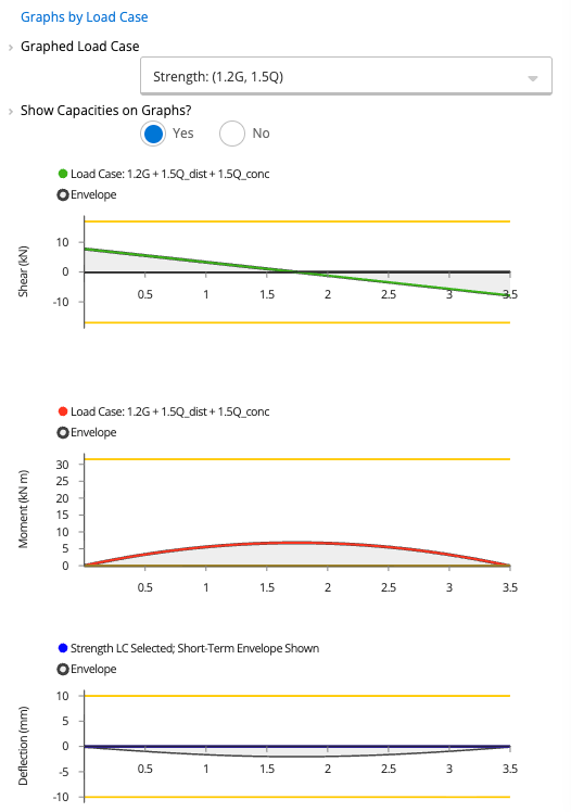
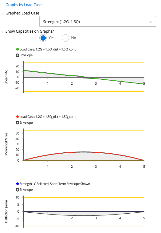
Graphs by Load Case shows the shear, moment and deflection graphs for the strength load case (1.2G, 1.5Q) by default. You can choose another load case in Graphed Load Case.Graphs by Load Case section with the strength load case 1.2G, 1.5Q selected and shear, moment and deflection graphs for the 3.5 m beam.
Inputs, Calcs.com output and a hand check

Inputs

Section D × B300 mm × 130 mm
Concrete32 MPa, Normal-weight
Span L3500 mm
Supports2 pinned (0 mm, 3500 mm)
Bottom reinforcement3 × N12 (D500N12)
Concrete cover to bottom reinforcement50 mm
Top reinforcementNone
Shear reinforcementNone
Permanent load G0.9 kPa
Imposed load Q1.5 kPa
Load width1000 mm
Character of imposed loadFloors: Offices
Self-weightIncluded
Alternate imposed loadRemoved

Calcs.com output

Positive moment capacity ϕMu+\phi M_u^+31.5 kN·m (22%)
Shear capacity ϕVu\phi V_u17 kN (46%)
Short-term deflection δs\delta_s−1.87 mm (19%)
Long-term deflection δl\delta_l−5.02 mm (50%)
Imposed load deflection δQ\delta_Q−0.978 mm (10%)
Governing badge50%
Reaction, ultimate maximum7.76 kN
Reaction, ultimate minimum2.86 kN
Reaction, G3.18 kN
Reaction, Q2.63 kN

Hand check

Ultimate reaction: R∗=1.2G+1.5Q=1.2(3.18)+1.5(2.63)=R^* = 1.2G + 1.5Q = 1.2(3.18) + 1.5(2.63) = 7.76 kN, using the G and Q reactions shown by the sheet
Factored line load: w∗=2R∗/L=2(7.76)/3.5=w^* = 2R^* / L = 2(7.76) / 3.5 = 4.43 kN/m
Mmax=w∗L2/8=(4.43)(3.52)/8=M_{max} = w^*L^2 / 8 = (4.43)(3.5^2) / 8 = 6.79 kN·m, so M∗/ϕMu=6.79/31.5=0.22M^* / \phi M_u = 6.79 / 31.5 = 0.22
Vmax=R∗=V_{max} = R^* = 7.76 kN, so V∗/ϕVu=7.76/17=0.46V^* / \phi V_u = 7.76 / 17 = 0.46

This is a sanity check on the moment and shear demands only. It uses the 1.2G + 1.5Q load case shown on the graphs, with L = 3.5 m. The sheet takes the shear at the support, so V∗V^* equals the ultimate reaction. Calculator version 125, Generic Indoor Beam preset.

Simply supported and continuous RC beam worked examples

The numbers spoken in the video are from an older recording. Shear at 42%, a concrete shear strength of 26 kN and a web-crushing strength of 259 kN match the calculator’s default cover of 30 mm, and 259 kN is the web-crushing strength from before Amendment 2 reduced it by 10%. The worked example above is calculator version 125 with the 50 mm cover, which gives shear at 46% and a governing long-term deflection of 50%. The transcript is left as spoken.
Timestamps are from the video captions and show roughly where each part begins.
0:04

So now moving on to some examples. We’ll do two different examples. One, a simply supported beam and two, a more complex beam.

Example 1: simply supported beam

0:15

First, we’re just going to take just about the simplest possible beam you can imagine. There’s only tension reinforcement, simply supported, 3.5 meter total span.

0:26

We’re going to have an imposed load and a permanent load on it equal to one point five and zero point nine kilopascals, respectively.

0:35

We’ll assume this beam is in an office building that’s affecting the character of the imposed load.

0:40

We’re going to assume no transverse reinforcement, a load width of a simple flat one meter, and concrete strength of 32 megapascals.

0:52

Now we’re going to show the how the methodology and formulas work using our new reinforced concrete calculator in ClearCalcs [Now Calcs.com].

1:02

So I’ll load up my web browser.

1:06

And just go over to clearcalcs.com [Now Calcs.com].

1:22

And I’m gonna create a new project, just call it webinar for now, and add in a rectangular concrete beam on here.

1:32

So at the top here, we’re making similar assumptions to what I described in our webinar already. No torsion, no prestressing, and let me assume that, basically, you’re gonna be checking all the detailing on your own.

1:47

That’s not checked in this sheet.

1:52

So, for the simplified beam, our total dimensions were 300 depth, 130 millimeter, total breadth, 32 megapascal concrete, 3.5 meter length, and we said we only have tension reinforcement consisting of three N12 longitudinal beams, so no top reinforcement, no transverse reinforcement, a one meter load width with point nine and one point five kilopascal dead and live load respectively.

2:28

We’ll keep self weight in there.

2:31

Character of imposed load, we said this was an office building, and usually you’d be considering wind and some other loads as well. I’m going to be removing those from this just to simplify everything.

2:43

Again, we’ll address complex loading later on in another webinar some other time.

2:48

And then we end up with final results.

2:57

75% of our total capacity calculated. Our controlling factor is long term deflection and you can see how demands and capacities relate to each other in a summary box at the top here.

3:13

This sheet is going to follow through the full procedure we just described. So flexural strength calculated midspan. It’s going to calculate your uncracked neutral axis location and depth to neutral axis with Ku.

3:34

You’ll notice similar formulas as is… As we went through in the webinar earlier.

3:43

This is as typical an under reinforced beam.

3:46

Shear analysis, I mentioned that Vu max is not usually going to govern for you. Here, it’s calculated as 259 kilonewtons, whereas our capacity of the concrete is 26 kilonewtons, so we’re very far off from that web crushing limit actually occurring. That’s typically going to be the case for you.

4:12

And deflection analysis, calculating the effective second moment of area, and we have just our quick stability checks at the end as well.

4:24

So we see that moment is pretty far from governing, shear is at 42%.

4:27

If we had a whole… Had roughly double that shear, we may want to consider starting to add some fitments, but in the end, it’s going to be the long term deflection that’s governing here.

Example 2: more complex beam

4:41

So then going to our second example, that’s gonna be a more complex beam.

4:54

We’re going to assume that the first beam we calculated is resting on top of our more complex beam at a location of seven meters. We have a total 10 meter span length… Or, excuse me, total 10 meter beam length with spans of 3.5 meters, 4.5 meters, and then a cantilever on the end of two meters.

5:14

We’ll have two different sets of reinforcement that differ between positive moment and negative moment, N12 bars on the top and N10 bars at the bottom.

5:26

In positive moment regions, we’ll have three N10s at the bottom and just two N12s at the top.

5:36

Negative moment regions will have three N12s at the top and two N10s at the bottom.

5:42

This time, we’ll assume it’s a retail building. We’ll put in some basic R6 shear fitments at 200 millimeter spacing, increase our load width a little bit to 1.5 meters, and we’ll again use a 32 megapascal total concrete strength.

6:00

So going back into our calculator, duplicate that to… So we don’t need to reenter in our section shapes, which is the same depth of 300 millimeters and a 130 millimeters.

6:17

This time, our total beam length is 10 meters, so we’ll put in that.

6:24

Supports at 3,500 millimeters and 8,000 millimeters for our three point five and four meter… And 4.5 meter spacing. You can see those shown graphically in the lower right here.

6:41

So we were going to have N10s on the bottom and N12s on the top.

6:52

This time, we are including top reinforcement in positive moment regions in the mid spans here, but we have three longitudinal reinforcement beams on the top and two on the bottom.

7:07

Shear fitments, we are going to include those R6s at 200 millimeters.

7:14

These are going to be typical standard fitments that have two legs, just your standard closed rectangular fitment, and 90 degrees for a perpendicular fitment.

7:27

And then this time we do have differing reinforcement in negative moment regions, So this is going to copy from up… What we already entered up above, but we’re going to modify it a little bit for our negative moment regions to instead have three top reinforcements and two bottom reinforcements.

7:54

Same loading, except we’re going to increase load width to 1,500 millimeters, and we’re also going to link in previous beam that we calculated and all the reactions due to that and put that in at seven meters.

8:10

We then have a retail character imposed load instead of an office character imposed load and including self weight as normal.

8:19

And you notice at the top here that we do have a failure due to our stability checks.

8:28

Scroll down here. Our default assumption for stability checks is incorrect for a multi span beam, so we just need to enter in that it’s 4,500 millimeters, the maximum length of our span, and that works just fine. We no longer have a failure there.

8:46

We can see again here that we’re making a bit more productive use of our flexural capacity. Still a lot of space there, but we’re only… But we’re using about a third of our flexural capacity in both cases.

9:04

Deflection is what’s going to be controlling for us. We have a yellow shown here for being above 90%, but that still works and making a bit more use of our shear capacity here at 54%.

How to Design a Concrete Beam Using AS3600:2018 in Calcs.com from Calcs.com.

Method & scope

See the exact clause

Every check in this calculator links back to its governing clause in AS 3600:2018. Click the label of any result, then select the clause button under References to read it. See Viewing Clauses from Inside a Calculator.

Calculation method

The Concrete Beam calculator designs rectangular reinforced concrete beams to AS 3600:2018 (Amendment 2) using limit state design. A live FEA engine resolves internal forces for unlimited span and load configurations, and checks are performed for flexure, shear, and deflection at critical sections.

Flexural capacity (AS 3600:2018, Cl 8.1)

Positive and negative moment capacities are computed using the rectangular stress block. For a singly reinforced rectangular section: Mu=Ast×fsy×(d−γ×ku×d/2)M_u = A_{st} \times f_{sy} \times (d - \gamma \times k_u \times d / 2) where dd is the depth to the tensile steel and kuk_u is the neutral axis depth ratio. The stress-block depth factor, with fc′f'_c in MPa, is γ=max⁡(0.67, 0.97−0.0025×fc′)\gamma = \max(0.67,\ 0.97 - 0.0025 \times f'_c) The capacity factor ϕ\phi is from Table 2.2.2. For N-class reinforcement and no axial force: ϕ=max⁡(0.65, min⁡(0.85, 1.24−13×ku/12))\phi = \max(0.65,\ \min(0.85,\ 1.24 - 13 \times k_u / 12)) A ductile section reaches 0.85. L-class bars are held at 0.65. The factored capacity is ϕ×Mu\phi \times M_u. Minimum reinforcement (Cl 8.1.6.1) is enforced: Ast,min=0.20×(D/d)2×(fct,f′/fsy)×bw×dA_{st,min} = 0.20 \times (D/d)^2 \times (f'_{ct,f} / f_{sy}) \times b_w \times d where fct,f′f'_{ct,f} is the flexural tensile strength of concrete.

Shear capacity (AS 3600:2018, Cl 8.2, simplified method)

Concrete shear strength (Cl 8.2.4.1), within the limits of Cl 8.2.4.3: Vuc=kv×bv×dv×fc′V_{uc} = k_v \times b_v \times d_v \times \sqrt{f'_c} fc′\sqrt{f'_c} is capped at 8 MPa. Where the fitments are below the minimum, and dvd_v is in millimetres: kv=min⁡(0.15, 200/(1000+1.3×dv))k_v = \min(0.15,\ 200 / (1000 + 1.3 \times d_v)) Otherwise kv=0.15k_v = 0.15. The simplified method applies when fc′≤65f'_c \le 65 MPa, fsy≤500f_{sy} \le 500 MPa, with no prestress and no tension or torsion. The ultimate shear strength is Vu=min⁡(Vuc+Vus, Vu,max)V_u = \min(V_{uc} + V_{us},\ V_{u,max}) For vertical fitments, Vus=(Asv/s)×fsy.f×dv×cot⁡(θv)V_{us} = (A_{sv} / s) \times f_{sy.f} \times d_v \times \cot(\theta_v), and the simplified method takes θv=36°\theta_v = 36°. With no fitments, Vus=0V_{us} = 0 and ϕ=0.70\phi = 0.70. With N-class fitments at or above the minimum, and VuV_u below Vu,maxV_{u,max}, ϕ=0.75\phi = 0.75 (Table 2.2.2). The factored capacity is ϕ×Vu\phi \times V_u.

Deflection checks (AS 3600:2018, Cl 8.5)

Three deflection limits are verified:
  • Short-term deflection: using the effective second moment of area IefI_{ef} under short-term service loads
  • Long-term deflection: adding a creep/shrinkage multiplier kcsk_{cs} to the sustained-load deflection
  • Imposed load deflection: deflection due to live load only, checked against the imposed deflection limit
The effective second moment of area is Equation 8.5.3.1(1). For a simply supported span: Ief=Icr/(1−(1−Icr/Ig,uncr)×(Mcr/Ms∗)2)I_{ef} = I_{cr} / \left(1 - \left(1 - I_{cr} / I_{g,uncr}\right) \times \left(M_{cr} / M^*_s\right)^2\right) The ratio Mcr/Ms∗M_{cr} / M^*_s is capped at 1, and IefI_{ef} is capped at Ief,maxI_{ef,max}. Long-term deflection adds kcsk_{cs} times the sustained-load deflection to the short-term deflection. With no compression reinforcement, kcs=2k_{cs} = 2. Each result is checked against the lesser of the absolute deflection limit and the L/nL/n span limit.

Assumptions

The eight items in the Key assumptions row are the list under the calculator’s Sheet Details. No torsional demands are considered. Prestressing and post-tensioning are not included. Secondary effects on shear (VucV_{uc}) and load reversal are not considered. Beams are assumed to be enclosed within the building. Concrete detailing (bar laps, anchorage, hooks) is checked separately (see Cl 4, 5, 8.3, and so on).

Symbols

The names below are the labels the calculator shows in its inputs and Summary.

How to use it

1

Open the calculator

Open it from Run calc in the About this calculator panel above. To start from a typical setup, choose one of the presets listed there. You can also choose Add New Calculation in a project, select Concrete Beam under Beams, and pick a preset.Add a new calculation window with Concrete Beam selected under Beams and its two presets listed below, Generic Indoor Beam and Retaining Wall Sleeper.
2

Set the section and the concrete

Key Properties starts with the Type of Beam, then the section sizes in mm. Type of Beam is Rectangle or T-Beam. Rectangle uses Total Depth of Cross-Section (D) and Total Breadth of Cross-Section (B). T-Beam keeps the depth and replaces the breadth with Flange Width or Beam Spacing, Flange Thickness and Web Width.Concrete Strength and Type shows the selected concrete. Select… opens a list of concrete designations. Type in the filter box, or use the Density filter and the Min and Max boxes to narrow the list. Each row shows the designation, fc′f'_c, fct.f′f'_{ct.f} and fct′f'_{ct} in MPa, a summary of checks as percentage badges, and a Governing limit column. If the concrete you need is not in the list, use the “Let us know and we will add it” link at the bottom of the window.Click any input label to see its reference explanation, clause, conditions and assumptions. See Checks, References, Conditions and Assumptions.Key Properties section of the Concrete Beam calculator with the Type of Beam dropdown, the total depth and total breadth of the cross-section, and the Concrete Strength and Type box with its Select button.Concrete Strength and Type window with a filter box, a Density filter, Min and Max boxes, and a list of normal-weight concrete designations from 20 to 65 MPa with their strengths and check badges. The 32 MPa row is ticked.
3

Enter the length and the supports

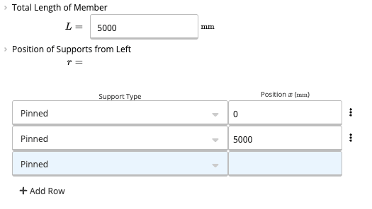
Total Length of Member (L) is in mm. It is the distance from the start of the beam to the end, including any intermediate supports, and it does not account for slope. In the Position of Supports from Left table, choose a support type for each support and enter its position (x), the distance from the left end of the beam to the center of the support. The support types are Fixed, Pinned and Roller.If a support is not at 0, the calculator assumes a cantilever on the left side of the beam. If the last support is not at the end of the beam length (L), it assumes a cantilever at the end.The in-app explanation still tells you to set a bearing length to 0 when bearing is irrelevant. The table has no bearing-length column. It has Support Type and Position only.Total Length of Member field and the Position of Supports from Left table with two pinned supports, each with a support type and a position in millimeters, and an Add Row button.
4

Set the fire resistance

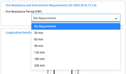
Fire Resistance and Environment Requirements has one dropdown, Fire Resistance Period (FRP), in minutes, for concrete beams. The choices are No Requirement, 30, 60, 90, 120, 180 and 240 min. See AS 3600:2018 Cl 5.4.Fire Resistance Period dropdown open with the choices No Requirement, 30 min, 60 min, 90 min, 120 min, 180 min and 240 min.
5

Enter the bottom reinforcement

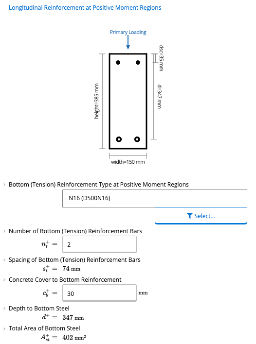
Longitudinal Reinforcement at Positive Moment Regions starts with a diagram of the cross-section and its bars. Choose the bottom (tension) reinforcement type with Select…. The calculator assumes the reinforcement is arranged in a single row.Enter the number of bottom bars. The in-app explanation says minimum reinforcement is required so that the section is at least ductile (AS 3600:2018 Cl 8.1.6.1), and that plain concrete with no reinforcement cannot be analyzed with this sheet.Spacing of Bottom (Tension) Reinforcement Bars is shown by the calculator. It is the centre-to-centre spacing along the width, and the sheet uses the bottom cover as the side cover. The in-app text says the spacing is restricted so the concrete can flow (Cl 8.1.9). The check that runs is a maximum: the spacing must be at most 300 mm. The sheet does not check a minimum clear gap between bars.Concrete Cover to Bottom Reinforcement is the distance from the bottom concrete surface to the bottom of the tensile reinforcement. Cover must be at least 20 mm in all cases, but the minimum cover requirement is often greater. See Cl 4.10 for the requirements based on exposure classification, concrete characteristic strength and other factors.Depth to Bottom Steel and Total Area of Bottom Steel are shown by the calculator.Longitudinal Reinforcement at Positive Moment Regions section with a cross-section diagram, the bottom reinforcement type with a Select button, the number of bottom bars, the bar spacing, the concrete cover to the bottom reinforcement, the depth to the bottom steel and the total area of bottom steel.
6

Enter the top reinforcement

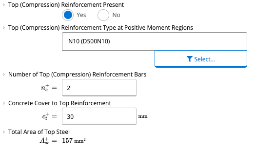
Top (Compression) Reinforcement Present is Yes or No: select it if top reinforcement is used in the section analysis. If it is, choose the type with Select…, then enter the number of top bars and the concrete cover to the top reinforcement. If no top reinforcing is required, select No. Total Area of Top Steel is shown by the calculator.Longitudinal Reinforcement at Negative Moment Regions stays hidden while the beam has no negative moment. It appears for a cantilever or a continuous beam. Its bar types, counts and covers start as copies of the positive-moment reinforcement.Top (Compression) Reinforcement Present choice set to Yes, with the top reinforcement type and its Select button, the number of top bars, the concrete cover to the top reinforcement and the total area of top steel.
7

Add the shear reinforcement

Under Transverse Shear Reinforcement at Supports, select Yes if shear reinforcement (fitments) is used in the section analysis. Area of Steel per Fitment Bundle is shown below it.When it is Yes, the sheet also asks for the Shear Fitments, the Number of Legs per Fitment Bundle (default 2), the Spacing of Fitments (default 200 mm) and the Inclination of Fitments (default 90°). Selected fitments are assumed to continue up to the face of the support, and to be vertical and perpendicular to the tensile reinforcement.Transverse Shear Reinforcement at Supports section with the Shear Reinforcement Present choice and the Area of Steel per Fitment Bundle.
8

Add the distributed loads

Distributed loads are spread continuously over the surface area of a member, for example the weight of tiles on a floor. The load width is the tributary width that loads the beam, and the calculator multiplies the area load by it. A load can start and end at any location, and its start and end magnitudes can differ. All distributed loads are applied perpendicular to the beam.The table has a Link from Calculator button, for a wide reaction or a load calculator. The in-app explanation still says no loads can be linked into this table. That sentence is out of date. To link a joist or a rafter, use the Line Loads table.Loads section with a diagram of the beam showing the alternate imposed load at one point, the floor load and the self-weight, above the Distributed Loads table with columns for label, start and end location, start and end load width and load magnitudes, and the Add Row and Link from Calculator buttons.
9

Add line, point and moment loads

A line load is a continuous length of the beam that is loaded. You can link repeating joists and rafters into the Line Loads table with the chain link icon on the right side of the table, and the calculator approximates the reaction as a constant distributed line load.A point load acts over a relatively small area, for example a weight hung from a ceiling or a column supported by the beam. A moment load causes rotation of a member about an axis. You can link another beam or column that bears on this one into the Point & Moment Loads table with the chain link icon.Each load magnitude uses a type from the sheet’s list: dead (G), live (Q), alternate live (Q2 and Q3), ultimate and service wind up and down, ultimate and service earthquake, and ultimate and service snow. The Generic Indoor Beam preset places only G and Q on the floor load, plus one Alternate Imposed point load. It does not place a wind load.Choose whether to include the self-weight of the member in the calculations, then pick the Character of Imposed Load from the dropdown: Floors: Residential and Domestic, Floors: Offices, Floors: Parking, Floors: Retail, Floors: Storage, Floors: Other, Roofs: Used for Floor-Type Activities, Roofs: All Other, Balustrades, or Long-Term Machinery, Tare Weight.Line Loads table and Point & Moment Loads table, each with Add Row and Link from Calculator buttons, followed by the Include Self Weight choice and the Character of Imposed Load dropdown.
10

Check the design criteria

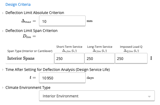
Design Criteria holds the Deflection Limit Absolute Criterion (mm) and the Deflection Limit Span Criterion, a table of short-term service, long-term service and imposed load limits for interior and cantilever spans. It also has the Time After Setting for Deflection Analysis (Design Service Life) in days and the Climate Environment Type. The climate choices are Arid Environment, Interior Environment, Temperate Inland Environment, and Tropical / Near-Coastal / Coastal.Three later sections are not in the screenshot. Member Properties has a maximum and a minimum beam depth. Set either to 0 to turn that check off. Creep Analysis has Concrete Age at Time of Initial Loading, which defaults to 28 days. Stability Analysis (Cl 8.9) has the Distance Between Interior Lateral Restraints, which defaults to the longest span.Design Criteria section with the deflection limit absolute criterion, the deflection limit span criterion table for interior spans, the time after setting for deflection analysis and the climate environment type dropdown.
11

Read the summary

The Summary lists the positive moment capacity, the shear capacity and the short-term, long-term and imposed load deflections, each with a utilization badge. The Reactions diagram below it shows the reaction at each support.Summary section listing the positive moment capacity, the shear capacity and the three governing deflections, each with a utilization badge, above a Reactions diagram of the beam on two supports.
12

Check the graphs by load case

Graphs by Load Case shows the shear, moment and deflection graphs for the load case you choose in Graphed Load Case. Use Show Capacities on Graphs to show or hide the capacities on the graphs.Graphs by Load Case section with the Graphed Load Case dropdown, the Show Capacities on Graphs choice, and shear, moment and deflection graphs for the strength load case.
13

Open a result to see its clause

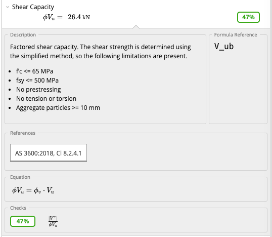
Click a result label to open its Description, Formula Reference, References, Equation and Checks. Select the clause button under References to read the clause from AS 3600:2018 inside the calculator. See Viewing Clauses from Inside a Calculator.Shear Capacity result expanded to show its Description, Formula Reference name, References button for the clause, Equation and Checks boxes.
14

Review the results and export

Check the utilization of each governing check in the summary, then export a PDF report. See Views and Export.

Available presets

Each preset opens the calculator with a typical setup already entered.

Common questions

Limit state design to AS 3600:2018 (Amendment 2). Factored loads from AS 1170.0 load combinations are compared to design capacities for flexure and shear. Deflection checks use serviceability load combinations.
Key inputs are the section (Rectangle, or a T-beam with flange width, flange thickness and web width), concrete strength and type, the bar selected for each face (its yield strength comes with the bar), cover measured to the face of the bars, bar counts, fitments when shear reinforcement is on, span and supports (Fixed, Pinned or Roller), and loads. Load types are dead, live, alternate live, wind up and down, earthquake and snow. The preset does not enter a wind load for you.
The calculator checks: positive moment capacity ϕ×Mu+≥M∗\phi \times M_u^+ \ge M^* (AS 3600:2018 Cl 8.1), negative moment capacity ϕ×Mu−≥M∗\phi \times M_u^- \ge M^* (Cl 8.1), shear capacity ϕ×Vu≥V∗\phi \times V_u \ge V^* (Cl 8.2 simplified method), governing short-term deflection, governing long-term deflection (with multiplier kcsk_{cs}), and imposed load deflection. Minimum reinforcement (Cl 8.1.6.1) is enforced. Lateral stability (Cl 8.9) checks the distance between lateral restraints against the section depth and breadth.
The effective second moment of area follows Equation 8.5.3.1(1). For a simply supported span, Ief=Icr/(1−(1−Icr/Ig,uncr)×(Mcr/Ms∗)2)I_{ef} = I_{cr} / (1 - (1 - I_{cr} / I_{g,uncr}) \times (M_{cr} / M^*_s)^2), with the moment ratio capped at 1 and IefI_{ef} capped at Ief,maxI_{ef,max}. Long-term deflection adds kcsk_{cs} times the sustained deflection to the short-term deflection. With no compression reinforcement, kcs=2k_{cs} = 2. Shrinkage and creep are calculated under Cl 3.1.7 and Cl 3.1.8 and feed that deflection.
Shear uses the simplified method. Concrete shear strength is Vuc=kv×bv×dv×fc′V_{uc} = k_v \times b_v \times d_v \times \sqrt{f'_c} (Cl 8.2.4.1), valid when fc′≤65f'_c \le 65 MPa, fsy≤500f_{sy} \le 500 MPa, with no prestress, tension or torsion (Cl 8.2.4.3). The older β1β2β3\beta_1 \beta_2 \beta_3 form is not used. The maximum shear at supports is taken directly over or at any distance from the support. The Cl 8.2.3.2 reduction at a distance dvd_v from the support face is not applied.
Beam support reactions link directly to connected column and footing calculations in the same Calcs.com project. When any load or geometry changes in the beam, the downstream column and footing calculations update automatically, keeping the full gravity load path consistent without manual data transfer.

Next steps

Design a Concrete Column to AS3600:2018

Design rectangular and circular reinforced concrete columns to AS 3600:2018 (Amdt 2), with P-M interaction, biaxial bending, slenderness and shear.

Use the Concrete Pad Footing Calculator AS 3600:2018

Design concrete pad footings to AS 3600:2018 (Amdt 2) with instant moment, shear and punching shear results.

Calculate Concrete Development Length to AS 3600:2018

Calculate tension and compression development lengths for reinforcement to AS 3600:2018 (Amdt 2), with code references and modification factors.

Changes in AS3600:2018 Amendment 2 (Concrete)

Changes in AS 3600:2018 Amendment 2 that affect Calcs.com concrete calculators: capacity reduction factor, shear strength, fitment spacing and variables.