

AustraliaAS 4100:2020

Beam reactions link to the columns and footings below, so load changes propagate downstream automatically. Design steel beams to AS 4100:2020 with multiple supports and loads. Floor- and roof-beam presets cut repetitive entry.
Method & scope
Scope
This sheet calculates maximum design actions and the associated capacities of a uniaxially loaded steel beam with multiple supports and loads. Maximum deflection is calculated along the length of the beam and can be either upward or downward.General Notes
- The main outcome of this sheet is to design for a steel beam against moment, shear and deflection. The steel beam is assumed to be uniaxially loaded.
- The supports for the steel beam are assumed to be pinned (hinged) or fixed supports and can be located anywhere along the beam. A minimum of 2 pinned or 1 fixed supports are required and they do not necessarily need to be at either end of the beam.
- Reaction forces are calculated for dead and live loads on all supports
-
Information/inputs required from the user:
- Dimensions and Member Section Properties
- Selected member for steel beam
- Span Length in mm
- Effective length, in mm
-
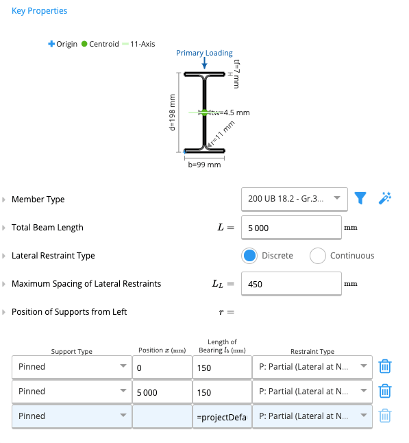
Location of supports in tabular form. If the first support is not at 0, it is assumed that the left-hand side of the beam is cantilevered. If the last support input is not equal to the length of the beam, the beam is cantilevered.
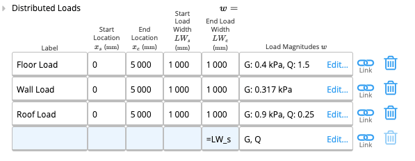
- Patch Load Table
- Magnitude of the permanent portion of the patch load in kN/m
- Magnitude of the imposed portion of the patch load in kN/m
- Start location of the patch load from the left-hand side in mm
-
End location of the patch load from the left-hand side in mm
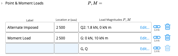
- Point Load & Applied Moment Table
- Magnitude of the permanent portion of the point load in kN
- Magnitude of the imposed portion of the point load in kN
- Location of the point load from the left-hand side in mm
- Magnitude of the permanent portion of the applied moment load in kNm
- Magnitude of the imposed portion of the applied moment load in kNm
-
Location of the applied moment load from the left-hand side in mm
- Self-weight toggle
-
User specifies if self-weight is applied to the analysis.

-
User specifies if self-weight is applied to the analysis.
- Limit state of analysis – Strength or Serviceability load case for analysis
- Character of imposed actions (live loads) as per AS1170.0
- Deflection limit factor, ka where deflection is compared using AS1170.0 (Span/ka) and maximum absolute deflection limit (mm)
- Dimensions and Member Section Properties
Assumptions and Limitations
- The beam is analyzed according to the specified geometry with up to 10 pin supports, located anywhere along the beam. This is solved for indeterminacy as well. Maximum moments, shear and deflection are calculated. It is not checked for combination actions
- All lengths are calculated and expected to be specified from the left-hand side of the beam. This includes the entire length of the span and the location of the supports, the applied loads and moments.
- Judgment is required for the use of the beam. Roof and floor uses is permissible and chosen by its character of imposed action.
- Only sections available from OneSteel Seventh Edition Hot Rolled Structures are available for analysis.
- Non-uniform stresses in sections is assumed to occur in SHS and RHS and is assumed to follow the design capacity guidelines as specified by AusTubeMills Design Capacity Tables Part 5
- Beams are computed by a chosen limit state and load combination. It is up to the user to choose limit states to determine the worst loading case combination
- P-Delta effects of long term deflection and moments are ignored for the purposes of the analysis
References
AS4100:1998 – Steel Structures AS1170.0:2002 – Structural Design Actions: General Principles AS1170.1:2002 – Structural Design Actions: Permanent, imposed and other actions Gorenc, B.E. & Tinyou, R. & Syam, A. A. (2012) Steel Designer’s Handbook. Sydney, NSW:New South Publishing OneSteel (2014) Seventh Edition Hot Rolled and Structural Steel Products. OneSteel Manufacturing AustubeMills (2013) Design Capacity Tables for Structural Steel Hollow Sections. Australian Tube MillsSee the exact clause
Calculation method
The Steel Beam (AS 4100:2020) calculator designs steel beams using limit state design (LRFD) per AS 4100:2020. Factored load demands are checked against design capacities for bending, shear, bearing, and deflection. A live FEA engine solves for moment, shear, and deflection under all AS/NZS 1170.0 load combinations simultaneously.Structural analysis
The beam is modeled as a 1D beam element. The FEA solver computes moment, shear, reaction, and deflection envelopes for every load combination. Distributed loads, line loads, point loads, and moment loads are all supported. Wind loads can be entered directly or linked from a wind load calculator.Moment section capacity (AS 4100:2020, Cl. 5.2 and 5.3)
Section moment capacity phi × M_s is calculated for bending about both principal axes (‘11’ and ‘22’). For standard I-sections and channels, the section is classified as compact, non-compact, or slender based on flange and web slenderness ratios per Table 5.2. Effective section modulus Z_e is used for non-compact and slender sections. utilization = M / (phi × M_s) ≤ 1.0*Member moment capacity, LTB (AS 4100:2020, Cl. 5.6)
For positive and negative bending, lateral-torsional buckling (LTB) capacity is computed separately. The reference buckling moment M_oa and slenderness reduction factor alpha_s are calculated as functions of the unbraced length, section properties, and moment modification factor alpha_m. A cantilever check per Table 5.6.2 is also available: phi × M_b = phi × alpha_m × alpha_s × M_sx ≤ phi × M_s utilization = M / (phi × M_gov) ≤ 1.0*Shear capacity (AS 4100:2020, Cl. 5.11) and shear-moment interaction (Cl. 5.12)
Shear capacity phi × V_v accounts for web yield and web shear buckling. Where shear and moment are both significant at the same section, the interaction check per Cl. 5.12 is applied.Bearing capacity (AS 4100:2020, Cl. 5.13) and bearing-bending interaction (Cl. 5.13.5)
Web bearing capacity phi × R_gov at each support is checked for web bearing yield and buckling. A combined bending and bearing interaction check is performed at supports where both are significant. Bearing is only checked for bending about the X-axis and must be checked separately by the engineer for Y-axis bending.Deflection analysis
Short-term (delta_s), long-term (delta_l), and imposed-load (delta_Q) deflections are each evaluated and checked against the span/limit criteria. Precamber can be specified and is reflected in the deflection diagrams.Assumptions
Beam is uniform cross-section. Net areas equal gross area with maximum allowable holes. Member moment capacity about the minor principal axis equals section moment capacity (M_b22 = M_s22). Angle sections are assumed restrained from lateral deflection and rotation. Moments are calculated about principal axes per Cl. 5.7.How to use it
1
Open the calculator
Open it from Run calc in the About this calculator panel above. To start from a typical setup, choose one of the presets listed there.
2
Enter your inputs
Work through the input sections from top to bottom. Click any input label to see its reference explanation, clause, conditions and assumptions. See Checks, References, Conditions and Assumptions.
3
Review the results and export
Check the utilization of each governing check in the summary, then export a PDF report. See Views and Export.
Steel Beam Design to AS 4100:1998
Lateral restraints input for steel beam design (AS 4100:2020)
Available presets
Each preset opens the calculator with a typical setup already entered.Common questions
What design method and standard does this calculator use?
What design method and standard does this calculator use?
The calculator applies limit state design (LRFD) per AS 4100:2020, Steel structures. Design actions (factored loads) are checked against design capacities for bending, shear, and deflection. Lateral-torsional buckling capacity is determined using the member moment capacity provisions of AS 4100:2020 Section 5.
What are the key inputs?
What are the key inputs?
Key inputs are span length, support conditions, steel section (from the Australian steel section database or custom), steel grade (250, 350, or 400 MPa), and applied loads (dead, live, wind, snow) per AS/NZS 1170.1 load combinations. You also specify unbraced length for LTB, bearing length at each support, and deflection limit ratios.
What does the calculator check and output?
What does the calculator check and output?
Checks include bending moment capacity (M*/phiMs and member capacity phiMbx with LTB), shear capacity (V*/phiVv), web crippling at supports, and deflection under serviceability loads versus span/ratio limits. Each check shows the governing AS 4100:2020 clause and the demand-to-capacity ratio.
Does the calculator cover compact, non-compact, and slender sections?
Does the calculator cover compact, non-compact, and slender sections?
Yes. The calculator classifies the section as compact, non-compact, or slender per AS 4100:2020 Table 5.2 based on the flange and web slenderness limits. For compact sections, the full plastic section modulus (Zx) is used. For non-compact and slender sections, effective section moduli are reduced accordingly.
How do I use this calculator with the Steel Lintel (AS 4100:2020) calculator?
How do I use this calculator with the Steel Lintel (AS 4100:2020) calculator?
The Steel Lintel calculator is specifically tailored for angle, T-section, and PFC+plate lintels over masonry openings, with masonry-specific load inputs and deflection limits. For standard rolled I-sections, channel sections, or hollow sections spanning as beams (not lintels), use this Steel Beam calculator instead. Beam reactions from either calculator can be linked to column calculations downstream.
Does this calculator support load linking with column and footing calculations?
Does this calculator support load linking with column and footing calculations?
Yes. Support reactions link directly to column and footing calculators in the same Calcs.com project. When span, section, or loading changes in this beam, the connected column and footing calculations update automatically, no manual re-entry of reactions.
Next steps
Design a Steel Lintel (Angle, T-Lintel or PFC+Plate) to AS 4100:2020
Design steel lintels supporting masonry, as an angle, a T-lintel, or a PFC with plate, to AS 4100:2020.
Design a Cold Formed Steel Beam to AS4600:2018
Design cold-formed steel beams to AS/NZS 4600:2018 using the Direct Strength Method, with a built-in database of Australian CFS sections.
Design a Steel Column to AS 4100:2020
Design hot-rolled steel columns and posts to AS 4100:2020. Checks axial section capacity, member buckling and combined axial and bending.