

AustraliaAS 1720.1:2010 (Amdt 3)

Design and analyze timber beams with multiple spans and load cases to AS 1720.1:2010. Beam reactions link to connected column and footing calculations automatically. Supports continuous, propped cantilever, and inclined configurations with bending, shear, bearing, and deflection checks.
Calcs.com allows you to design a timber beam according to AS 1720.1:2010 in a few simple steps, with checks for moment capacity, shear capacity, bearing capacity and deflections.
For a basic introduction to the beam design/analysis setup, see the article ’ Use the Beam Analysis Calculator’.
Method & scope
See the exact clause
References
AS1720.1:2010 – Timber Structures AS1684.2:2010 – Residential Timber-Framed Construction: Non-cyclonic Areas AS1170.0:2002 – Structural Design Actions: General Principles AS1170.1:2002 – Structural Design Actions: Permanent, imposed and other actions AS1170.2:2011 – Structural Design Action: Wind actionsWhat it calculates
Beam reactions link to your column and footing calculations automatically, multi-span configurations update downstream calcs when you change any load or span. Analyses continuous, propped, and cantilevered timber beams to AS 1720.1:2010 with bending, shear, bearing, and deflection checks across all spans. Specify the products your project actually uses without leaving the calculation. The Australian section library carries 1,247 branded sections from 12 named suppliers. Those include Hyne glulam, NeXTimber GL13, and Wesbeam, Dindas and hySPAN LVL. You design against the properties those companies publish, instead of working from a separate manufacturer guide. Traffic-light checks for moment, deflection, and shear make results quick to interpret.Calculation method
Structural model
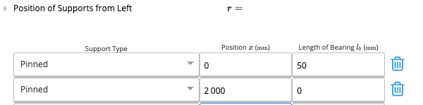
The calculator builds a finite element model of the beam with user-defined support positions and fixity conditions (pinned or fixed). Supports can be placed at any point along the beam length, making it possible to model simple spans, continuous beams over multiple interior supports, propped cantilevers, and beams with overhangs in a single calculation. For inclined members, rafters on a simple slope and hip or valley beams on a corner, the geometry is resolved automatically from the entered roof pitch or hip angle and tributary width, so load tributaries and gravity components are calculated consistently with the incline.Load combinations
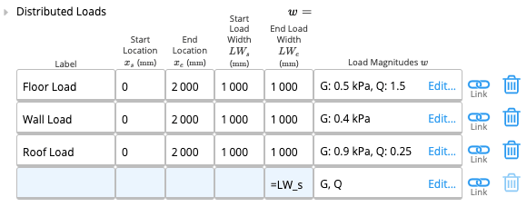
The calculator assembles all specified distributed, concentrated, and wind loads into the AS/NZS 1170.0 strength (ultimate) and serviceability load combinations. Permanent action (G), imposed action (Q), and wind action (W_s, W_u, both up and down) can be defined over any portion of any span. Alternate imposed loading, a reduced imposed load applied to half the span, is included in the default presets to capture pattern loading effects in continuous spans.Capacity checks
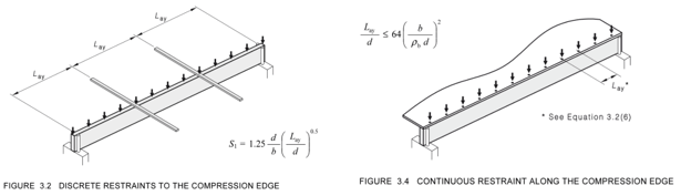
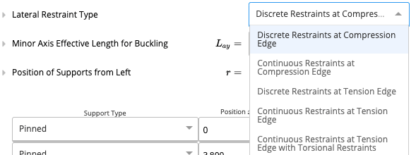
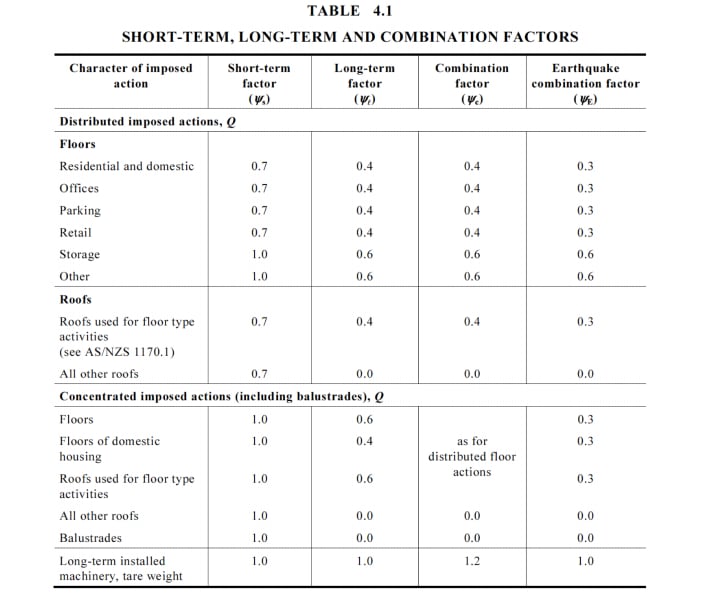
For every load combination the calculator evaluates the following limit states per AS 1720.1:2010: Bending capacity. The design bending moment M* is compared against the design capacity φM_d = φ k_1 k_4 k_6 k_9 k_12 f_b’ Z, where f_b’ is the characteristic bending strength, Z is the section modulus, and the modification factors account for load duration (k_1), partial seasoning (k_4), temperature (k_6), strength sharing between members in a system (k_9), and lateral stability (k_12). The partial seasoning factor k_4 is derived from the equilibrium moisture content you enter, per clause 2.4.2. The stability factor k_12 is determined from the slenderness coefficient S_1 using the lateral restraint spacing and effective length inputs for the compression edge. Shear capacity. The design shear force V* is compared against φV_d = φ k_1 k_4 k_6 f_s’ A_s, where f_s’ is the characteristic shear strength, A_s is the shear area, and the same duration, seasoning, and temperature factors apply. Shear is checked at the critical section per clause 3.2.5. Bearing capacity. The design reaction N* at each support is compared against φN_d = φ k_1 k_4 k_6 k_7 f_p’ A_p, per clause 3.2.6. Here f_p’ is the characteristic bearing strength perpendicular to grain and A_p is the bearing area. The bearing length entered at each support sets A_p and the length of bearing factor k_7, per clause 2.4.4. Enter a bearing length of zero to skip the check at a support where bearing is not relevant. Deflection. Short-term (imposed action) and long-term (permanent plus imposed action with creep factor applied to the permanent component) deflections are calculated by direct FEA integration. The calculator checks each span independently against the user-specified span-to-deflection ratios, defaults are L/250 for interior spans and L/150 for cantilevers. A hard absolute limit in millimeters is also available for sensitive finishes or brittle claddings.Section library and moisture conditions
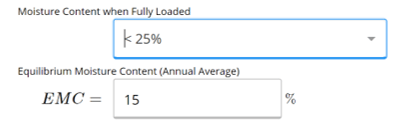
The section database covers thousands of standard Australian sawn, dressed, and engineered timber sections. That includes MGP grades, F-grades, glulam, structural LVL, I-joists and OSB. Of those, 1,247 sections are branded, carrying the characteristic values their manufacturer publishes: Hyne Timber, Metsa Wood, ITI, Louisiana-Pacific, Tilling Timber, NeXTimber, Carter Holt Harvey, Nelson Pine, Wesbeam, Egger, Dindas and Meyer Timber. Custom sections can be entered manually. Moisture inputs default to equilibrium moisture content (EMC) of 15% and fully-loaded moisture content (LMC) less than 25%, consistent with most non-exposed interior applications. EMC sets the partial seasoning factor k_4 applied to the bending and shear checks. Both inputs can be overridden for external or wet-area members.Outputs and load linking
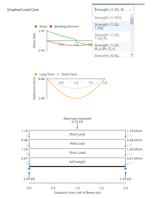
For each governing load combination the results show: moment, shear, and deflection diagrams with peak values; utilization ratios (demand/capacity ≤ 1.0) for each limit state; the governing modification factors; and traffic-light pass/fail indicators. Support reactions are available as linked outputs. When the timber beam calculation is connected to a timber column or pad footing calculation in the same project, the reaction updates automatically whenever any input in the beam calculation changes, span, section, load, or support position. Upstream linked inputs (dead load G and live load Q) from wind load calculators or other analyses update the beam automatically in the same way.How to use it
1
Select Beam Type
When adding a new timber beam calculation, you can select between various types of residential timber beam. The sheet and calculations for each are the same, however, some default values and criteria, such as deflection limits and center to center spacing, have been made specific to each beam type.Once you have created a timber beam, you may use the change material function to quickly swap to steel, or vice versa.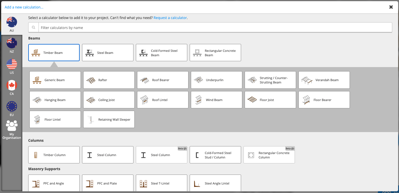
2
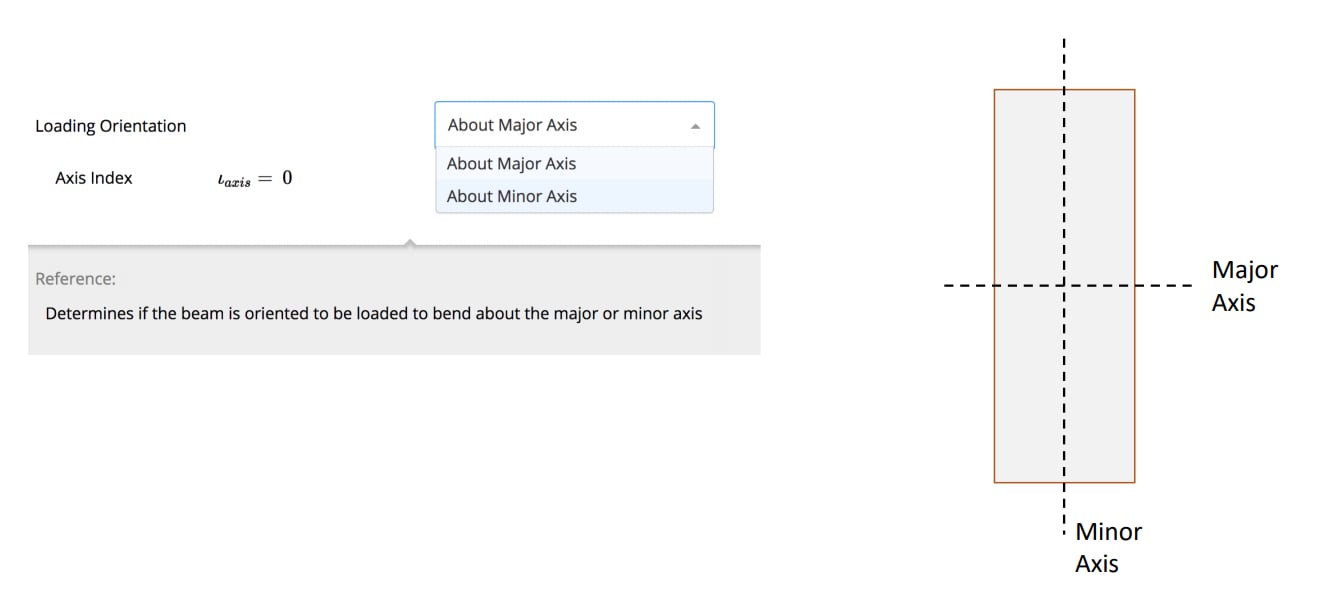
Input Key Properties
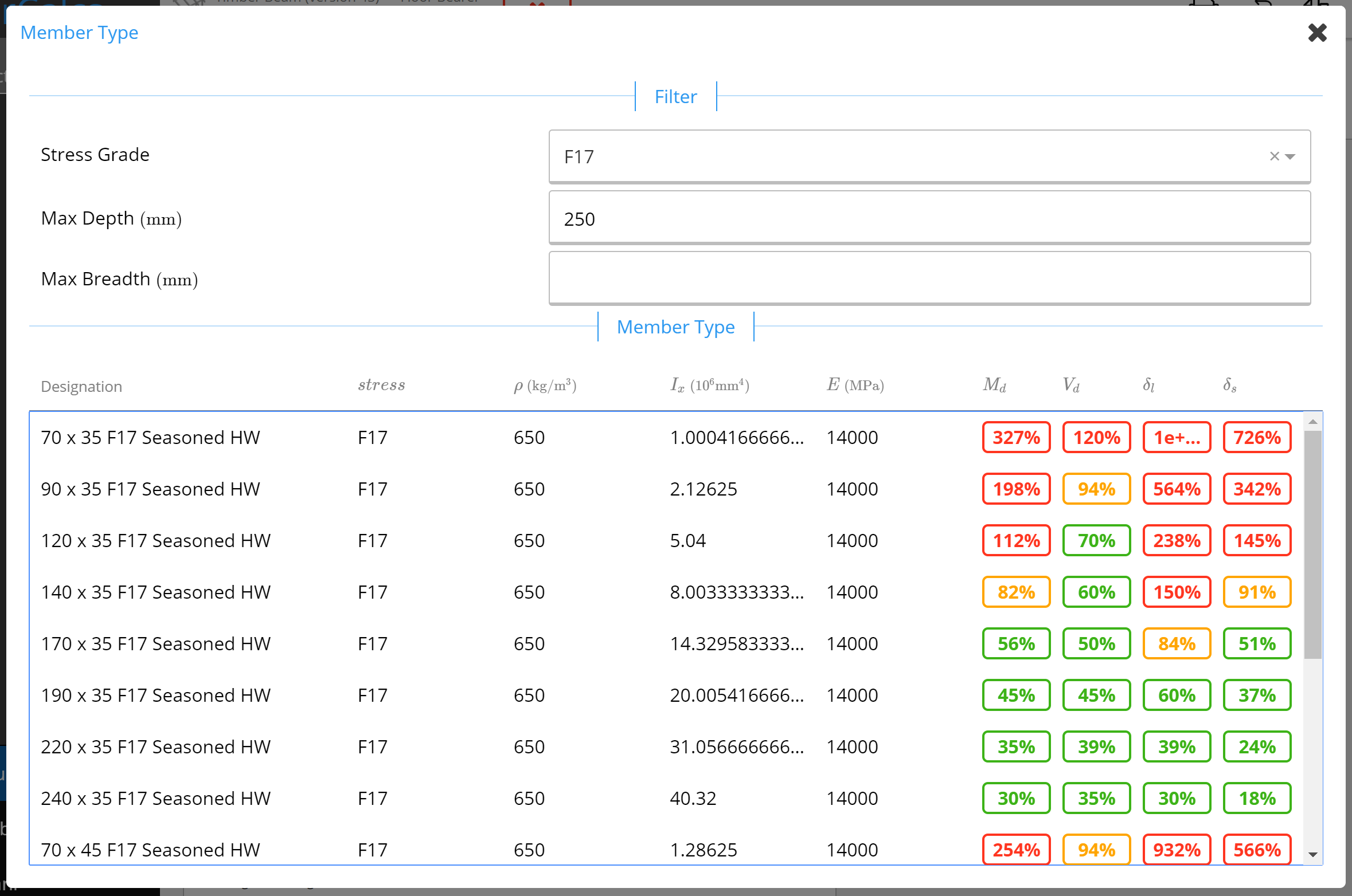
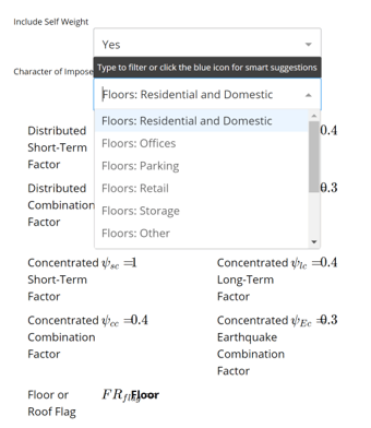
Quick Tip - If you’re ever unsure what something means in Calcs.com, simply click the field label for references, checks, conditionals, and descriptions.Member SelectorThe member selector can be used to filter the timber sections by stress grade, or by specifying the maximum dimensions required. The selector shows a summary of the critical checks, to help you to identify the most optimal section.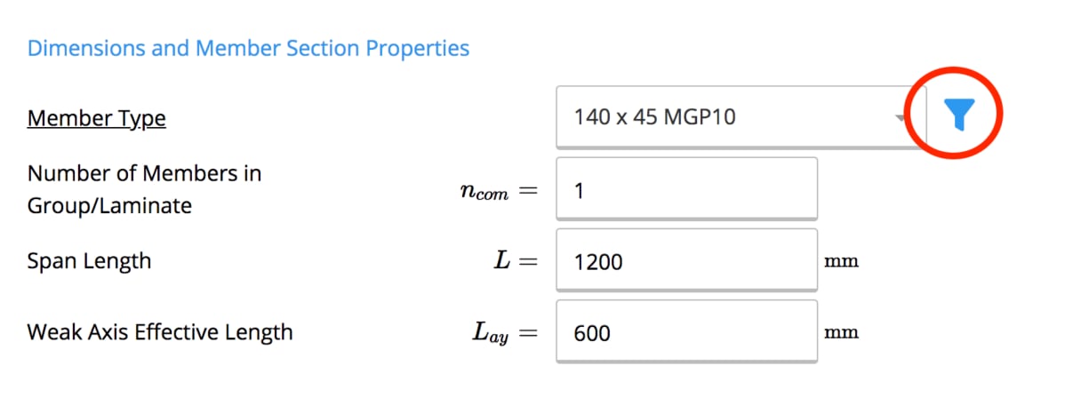


Tutorial | How to Design a Timber Beam in Calcs.com to AS1720.1 from Calcs.com.
Available presets
Each preset opens the calculator with a typical setup already entered.Common questions
What design standard does this calculator use?
What design standard does this calculator use?
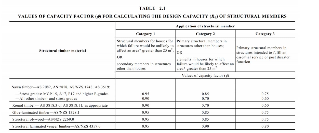
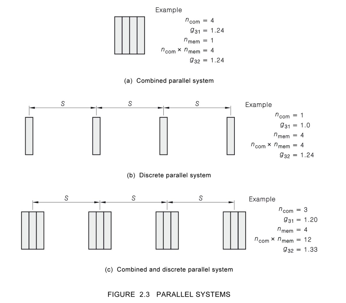
AS 1720.1:2010 with Amendment 3 (Timber Structures). The capacity factor (φ) and every modification factor are applied per the standard: load duration (k_1), partial seasoning (k_4), temperature (k_6), length of bearing (k_7), strength sharing (k_9), and lateral stability (k_12). The calculator selects the governing load combination from AS/NZS 1170.0 strength and serviceability load cases.
What types of beams and load configurations does it support?
What types of beams and load configurations does it support?
The calculator handles simple, continuous, propped-cantilever, and cantilevered beams with unlimited intermediate supports and spans. Distributed loads, concentrated loads, and wind loads (both up and down) can be applied to any span. Inclined configurations, horizontal, simple slope, and hip/valley geometry, are also supported.
What does it check and output?
What does it check and output?
For each load combination the calculator checks bending (M* ≤ φM_d), shear (V* ≤ φV_d), bearing at supports, and deflection against user-specified span/limit ratios. Interior spans default to L/250-L/300 and cantilevers to L/150. Results are displayed as traffic-light checks so you can immediately see which limit state governs.
Can it handle propped cantilevers or beams with intermediate supports?
Can it handle propped cantilevers or beams with intermediate supports?
Yes. Supports can be positioned at any point along the beam and defined as pinned or fixed. The FEA engine resolves the statically indeterminate system and generates moment, shear, and deflection envelopes across all spans, including propped-cantilever and back-span arrangements.
When should I use the Timber Member calculator instead?
When should I use the Timber Member calculator instead?
Use this calculator when load acts transversely on the beam and axial force is absent or negligible. It builds the analysis model from the spans, supports, and loads you enter. The Timber Member (Design Only) calculator suits members carrying significant axial load alongside bending and shear, such as truss chords and braced frame members. It takes member end forces (N*, M*, V*) directly from your own analysis rather than deriving them. Both design to AS 1720.1:2010.
Does this calculator support load linking, can support reactions link to connected column calculations?
Does this calculator support load linking, can support reactions link to connected column calculations?
Yes. Support reactions at each end link directly to connected timber column or footing calculations in the same project. When you change a span length, section size, or applied load, the updated reaction propagates automatically to every downstream calculation, no manual re-entry required.
Next steps
Design a Timber Member (Design Only) to AS 1720.1:2010 (Amdt 3)
Design timber truss chords, frame members and rafter ties to AS 1720.1:2010 (Amdt 3), with combined bending, axial and shear checks.
Design a Timber Bolt Connection to AS 1720.1:2010
Design timber bolted connections to AS 1720.1:2010. Checks bolt patterns under direct shear, in-plane moment, and tension for Australian timber construction.
Design a Timber Nail Connection to AS 1720.1:2010
Check the capacity of nailed timber connections to AS 1720.1:2010.
Design a Sloped or Angled Member
Design rafters, hip beams and other inclined members: set the slope, choose plan or inclined view, pick a load orientation, or convert lengths with formulas.