

CanadaCSA O86:19NBCC 2015Wood Design Manual 2017

The Calcs.com timber column calculator to CSA O86 enables the fast and accurate design of wood columns and studs to Canadian standards. With support for dynamic load linking between beams and columns, easily design accurate and quality engineered columns.
The Calcs.com Timber Generic Concentrically Loaded Column Calculator allows users to design timber columns by specifying the desired load cases and dimensions of the column assuming concentric loading. In this article, each section of the calculator will be explained followed by a few worked examples.
The Timber Column Calculator has 4 main sections
- Key Properties
- Loads
- Design Conditions
- Summary and Graphs
Worked example
Design a timber column with the following characteristics
- 3m in height with blockings (along the weak axis) every 1m
- member type: Douglas Fir, No1/No2
- fixed base and a roller support at the top
- an axial load at the top: 14kN/m dead load and 1500kN/m live load with 0.6m stud spacing
- assume zero eccentricity
- include self-weight
- assume dry service conditions, untreated with no load sharing
 An initial 2x8 Douglas Fir No1/No2 Member was selected for the design
Method & scope
See the exact clause
Calculation method
Structural model and load combinations
The calculator models the wood column as a member under combined axial compression and biaxial bending. Loads are entered by type, dead (D), live (L), snow (S), wind (W), and the calculator generates all governing NBCC 2015 / CSA O86:19 strength load combinations. Bending moments can be entered directly or received via load linking from beam calculations above.Axial compressive resistance (CSA O86:19 Cl.6.5.5.2.4)
Factored compressive resistance P_r is computed from the characteristic compressive strength F_c parallel to grain, adjusted by:- K_H, system factor
- K_Scp, service-condition factor for compression
- K_T, treatment factor
- K_c, slenderness factor, derived from the slenderness ratio C_c for each axis
Bending moment resistance (CSA O86:19 Cl.6.5.3.1 and Cl.7.5.6.5.1)
Factored bending resistance M_r is computed for both the X-axis and Y-axis using adjusted bending strength F_b. The lateral stability factor (Cl.7.5.6.5.1) accounts for buckling of the compression face and is applied independently for each axis.Combined bending and axial interaction (CSA O86:19 Cl.7.5.12)
When both axial compression and bending moments are present, the calculator checks the biaxial interaction equation per CSA O86:19 Cl.7.5.12, using the formulation from AWC Technical Report 14: interaction utilization = P_f/P_r + M_fx/M_rx + M_fy/M_ry ≤ 1.0 Where M_fx and M_fy are the factored bending moments about the strong and weak axes respectively. This single interaction check governs over the individual axial and bending utilizations when moments are present.Shear resistance (CSA O86:19 Cl.6.5.4.3)
Shear resistance is checked independently for forces applied in each direction, using the same adjustment factors applied to the bending checks.Bearing perpendicular to grain (CSA O86:19 Cl.6.5.6.2)
At the base of the column or wherever the member bears on a sill plate or other perpendicular-grain surface, factored bearing resistance Q_rp is computed from the characteristic compressive strength perpendicular to grain F_cp, adjusted for service condition and treatment.Load linking
The column’s axial reaction at its base is exported as a linked output to connected footing calculations. Axial load at the top can be linked from beam reactions above, so the full load path, beam to column to footing, updates automatically when any upstream input changes.How to use it
1
Key Properties
 A. Size & GradeThe user can select the size of the member they want to use from a list of industry-standard sized members by using the “Select” button. Using the corresponding filers, the user can view available options based on the chosen type, species, grade, manufacturer, and nominal size of the column.
 B. Number of PliesThe number of timber laminates in the column. This quantity needs to be either equal to or greater than 1. When plies are greater than, a fasteners system selection dropbox will appear. The user will need to choose a fastener type from the following dropbox for Calcs.com to factor in the appropriate built-up column strength reduction factor.
 C. Column HeightThe total height of the column needs to be given in millimeters (mm) or feet (ft).D. Lateral Restraint ConditionsThe user is prompted to specify whether the following conditions exist for the column that is being designed.
- Continuous bracing for strong (major) axis buckling
- Continuous bracing for weak (minor) axis buckling
- Continuous bracing for lateral-torsional buckling
2
**2. Loads**A. Load Diagram
The load diagram provides a live illustration of the column and the assigned loading.
3
B. Eccentricity
Generally, axial loads (i.e., loads acting vertically downwards) act through the center of a column. However, in some cases, the load can act off the center of the column and cause bending in addition to compression of the column. Axial load eccentricity refers to the horizontal distance between the center of the column and the line of action of the axial load.The default load eccentricity is set to zero (i.e. no bending, pure compression is assumed). If a user wishes to change this, they need to specify the new load eccentricity in inches (in) or millimeters (mm). Typically, many will consider using an eccentricity of 1/6th of the depth to accommodate for construction flexibility and connections.C. Axial Loads To enter an axial, point or moment load, one needs to fill out the above table. The first column refers to the name of the load, which can be decided by the user. Then the location at which the load acts on the column as measured from the bottom of the column (in feet or millimeters) needs to be entered.The third column refers to the axial eccentricity of the load; by default, this is set to the quantity specified in part A but can once again be changed to user preference. When one clicks on the fourth column or the “Edit” text, the following table will appear.
 In this table, the user can select the load type from the drop-down menu shown and specify the magnitude of the load in the x and y directions in Pounds(lb) or Kilonewtons (kN) and enter any moment loads in Pounds feet(lb-ft) or Kilonewton-meter (kN-m). Additionally, the link button can be used to import the loads from another calculation/sheet.D. Lateral Loads
 This table is applicable to distributed loads that act in the x-direction (i.e. perpendicular to the column). Like the Axial Loads table, the first column of the lateral distributed loads table prompts the user to name the load. Then the start and end location of the distributed load must be specified, as measured from the bottom of the column in feet (ft). Then the start and end width of the load must be entered in feet(ft) or millimeters (mm). Selecting the fourth column or the “Edit” text, you will see the following table.
 The load type must be selected from the drop-down menu in the first column, then the load magnitude must be specified per area in units of pounds per square foot(PSF) or kilopascals (kPA). Additionally, the link button can be used to import the loads from another calculation/sheet.E. Self-WeightThe user can choose whether they include the self-weight of the column in their calculations. The calculator is set to include the self-weight by default unless the user specifies otherwise.F. Weak Axis LoadingThe weak axis is the weaker orientation of a column that results in a smaller moment of inertia when compared to the strong axis. The weak axis loading section follows the same format as the strong axis loading. For this section, users only need to input the moment and lateral loads relevant to the weak axis.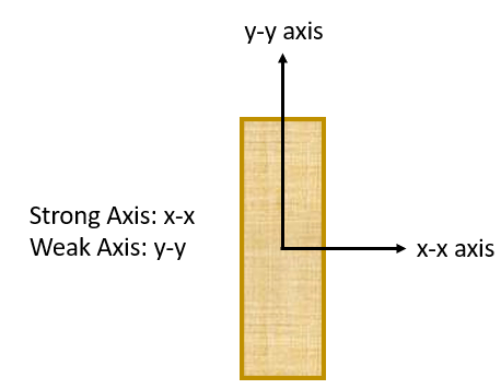
To enter an axial, point or moment load, one needs to fill out the above table. The first column refers to the name of the load, which can be decided by the user. Then the location at which the load acts on the column as measured from the bottom of the column (in feet or millimeters) needs to be entered.The third column refers to the axial eccentricity of the load; by default, this is set to the quantity specified in part A but can once again be changed to user preference. When one clicks on the fourth column or the “Edit” text, the following table will appear.In this table, the user can select the load type from the drop-down menu shown and specify the magnitude of the load in the x and y directions in Pounds(lb) or Kilonewtons (kN) and enter any moment loads in Pounds feet(lb-ft) or Kilonewton-meter (kN-m). Additionally, the link button can be used to import the loads from another calculation/sheet.D. Lateral LoadsThis table is applicable to distributed loads that act in the x-direction (i.e. perpendicular to the column). Like the Axial Loads table, the first column of the lateral distributed loads table prompts the user to name the load. Then the start and end location of the distributed load must be specified, as measured from the bottom of the column in feet (ft). Then the start and end width of the load must be entered in feet(ft) or millimeters (mm). Selecting the fourth column or the “Edit” text, you will see the following table.The load type must be selected from the drop-down menu in the first column, then the load magnitude must be specified per area in units of pounds per square foot(PSF) or kilopascals (kPA). Additionally, the link button can be used to import the loads from another calculation/sheet.E. Self-WeightThe user can choose whether they include the self-weight of the column in their calculations. The calculator is set to include the self-weight by default unless the user specifies otherwise.F. Weak Axis LoadingThe weak axis is the weaker orientation of a column that results in a smaller moment of inertia when compared to the strong axis. The weak axis loading section follows the same format as the strong axis loading. For this section, users only need to input the moment and lateral loads relevant to the weak axis.-
Design Conditions
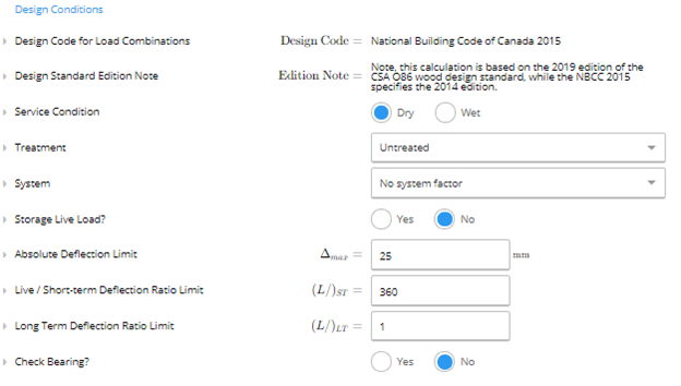
- Service Condition: The user can select if the service condition is ‘dry’ or ‘wet.’ It is considered wet if the moisture content of wood will exceed 19% for an extended time. Most often applies only to exterior use.
- Treatment: Users indicate if the wood column is untreated, or preservative-treated incised or unincited.
- System Factor: A system factor is considered if the member is part of a system where loads can be shared. There are three options.
- No System Factor: There are less than 3 columns spaced 610mm apart and/or are not mutually sharing loads
- Case 1: There are more than 3 columns spaced less than 610mm apart, mutually sharing loads
- Case 2: All the following conditions are met
- There are more than 3 columns spaced less than 610mm apart
- Members are sheathed with a minimum of 9.5mm OSB, waferboard, plywood or with min. 17mm lumber with panel coverings.
- The sheathing is attached with sufficient stiffness and adequate spacing equal to 2 common nails at 150 mm on center at edges and 300 mm on center elsewhere.
- Storage Live Load: A storage live load is a live load (loads due to occupancy use) that occurs for a long duration. An example of this is storage space items in an attic. If this is set to yes, an appropriate loading factor is assigned to accommodate for the storage live load.
- Absolute Deflection Limit: The maximum allowable deflection for the column set by the user in inches (in) or millimeters (mm)
- Live/Short-term Deflection Ratio: The maximum allowable deflection ratio for live and short loading. The default is L/360 but the user may indicate a smaller ratio if preferred.
- Long Term Deflection Ratio: The maximum allowable deflection ratio for long-term loading. The default is L/1 but the user may indicate a preferred ratio.
- Check Bearing: If this is set to yes, a bearing check will be performed assuming the column bears on a perpendicular member of the same material and grade.
4
Summary and Graphs
In the summary section, the key parameters of your calculation will be outlined. In the graphs section, the user can select the load combination that they would like the see in their graph.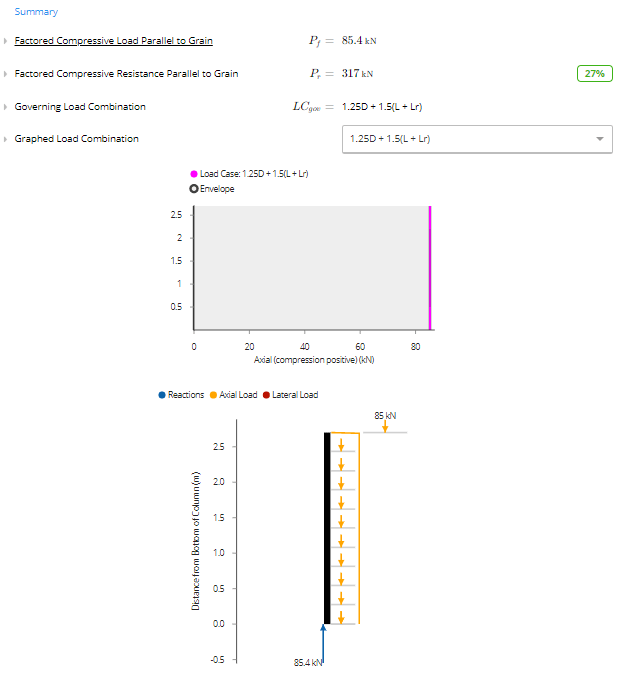

- Member Properties
- Load Combination Analysis
- Modulus of Elasticity
- Compression Resistance Parallel to Grain
Available presets
Each preset opens the calculator with a typical setup already entered.Common questions
What design standard does this calculator use?
What design standard does this calculator use?
The calculator designs wood columns to CSA O86:19 (Limit States Design) with load combinations per NBCC 2015. Biaxial bending interaction follows CSA O86:19 Cl.7.5.12, which references American Wood Council Technical Report 14 for the combined bending-plus-axial interaction equations.
What are the key inputs?
What are the key inputs?
Key inputs include the wood section (species, grade, and product type from the built-in database or a custom section), column height, number of plies, effective length factors for both axes, service condition (dry or wet), treatment, factored axial load, and bending moments about both axes from linked beam reactions or manually entered loads.
What checks and outputs does it produce?
What checks and outputs does it produce?
The calculator checks factored compressive resistance parallel to grain (CSA O86:19 Cl.6.5.5.2.4), factored bending moment resistance about both axes (Cl.6.5.3.1 and Cl.7.5.6.5.1), combined bending-plus-axial interaction (Cl.7.5.12), shear in both planes (Cl.6.5.4.3), and bearing perpendicular to grain (Cl.6.5.6.2). Slenderness ratios for both axes are computed per Cl.6.5.5.2.2.
How does biaxial buckling work for multi-ply columns?
How does biaxial buckling work for multi-ply columns?
For multi-ply (built-up) columns, the calculator applies the multi-ply compressive resistance provisions of CSA O86:19 Cl.6.5.5.4, which reduce the effective compressive resistance based on how the plies are connected. Slenderness ratios are computed independently for the X-axis (bending the full built-up section) and Y-axis (buckling of individual plies), and the governing direction controls.
Can it handle combined bending and axial loading?
Can it handle combined bending and axial loading?
Yes. The combined bending-plus-axial check follows CSA O86:19 Cl.7.5.12 using the interaction equations from AWC Technical Report 14. Moments can be entered directly or linked from beam reactions above the column. Both strong-axis and weak-axis moments are included in the interaction equation simultaneously.
Does this calculator support load linking with beam and footing calculations?
Does this calculator support load linking with beam and footing calculations?
Yes, axial load from beam reactions above links directly into the column, and the column reaction at its base links to connected footing calculations. Change a load or span in a beam above and the column and footing calculations below update automatically.
Next steps
Design a Wood Beam, Joist, and Girder to CSA O86
Design simple and continuous wood beams, joists and girders to CSA O86:19 with unlimited supports and loads. Checks moment, shear and deflection.
🇨🇦 Calculators for Canada
Complete list of Calcs.com design calculators available for Canadian projects (CSA O86, CSA S16, NBCC, and related standards).
Generalized Lateral Stability Calculation for Wood Beams
How the lateral stability factor KL for wood beams in bending is calculated to CSA O86:19, including effective lengths for common loading conditions.