Calculators used: Design a Wood Beam (ASD) to NDS 2024, Design a Wood Beam (LRFD) to NDS 2024
A flitch beam is a wood beam with one or more steel plates attached to it. In the Wood Beam (ASD) NDS 2024 calculator, set Add Flitch Plates? to Yes and enter the number, thickness, depth and yield strength of the plates. The calculator uses the modular ratio n=Es/E′n = E_s / E' to compare the steel with the wood in bending, and checks shear on the wood area only.

Worked example

Symbols

Example 1: the Generic Flitch Beam preset

The Generic Flitch Beam preset is read as it opens: a 5-1/2x16 24F-1.8E glulam beam over a 25 ft span, with two 0.375 in flitch plates, 15.75 in deep (shown as 15.8 in), with a yield strength of 36 000 psi. No input is changed. The run is on Wood Beam (ASD) NDS 2024, version 7, in a US customary project.
1

Read the section properties

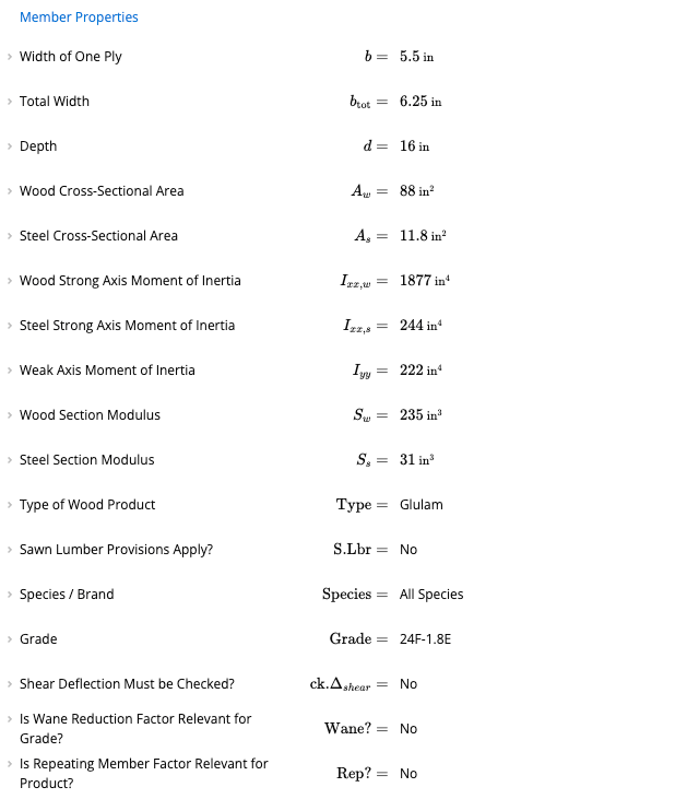
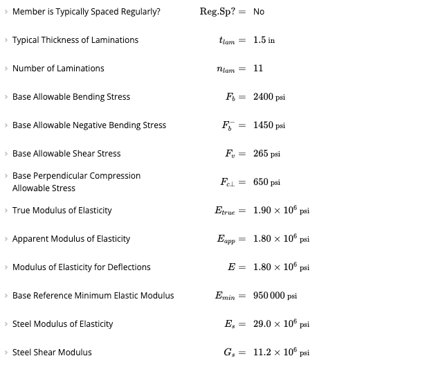
Member Properties lists the wood and steel parts of the section: a Total Width of 6.25 in, a Wood Cross-Sectional Area AwA_w of 88 in², a Steel Cross-Sectional Area AsA_s of 11.8 in², a Wood Strong Axis Moment of Inertia of 1877 in⁴, a Steel Strong Axis Moment of Inertia of 244 in⁴, a Wood Section Modulus of 235 in³ and a Steel Section Modulus of 31 in³.Member Properties with a Width of One Ply of 5.5 in, a Total Width of 6.25 in, a Depth of 16 in, a Wood Cross-Sectional Area of 88 in squared, a Steel Cross-Sectional Area of 11.8 in squared, a Wood Strong Axis Moment of Inertia of 1877 in to the fourth, a Steel Strong Axis Moment of Inertia of 244 in to the fourth, a Weak Axis Moment of Inertia of 222 in to the fourth, a Wood Section Modulus of 235 in cubed and a Steel Section Modulus of 31 in cubed.
2

Read the summary

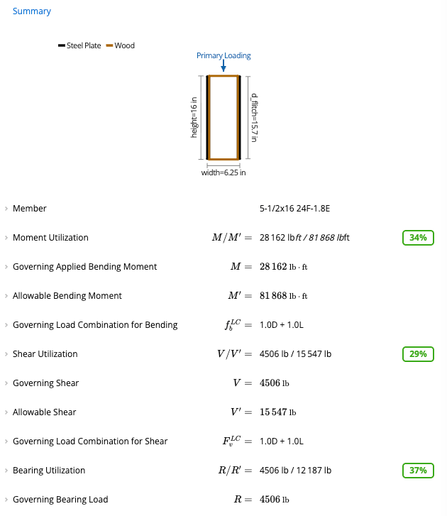
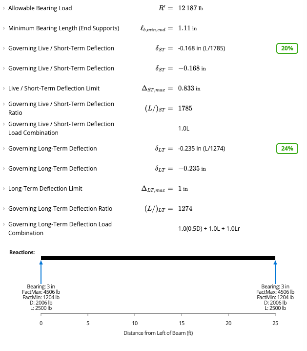
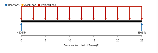
The Summary shows a Moment Utilization of 34% (28 162 lb·ft against an Allowable Bending Moment of 81 868 lb·ft), a Shear Utilization of 29% (4506 lb against 15 547 lb) and a Bearing Utilization of 37% (4506 lb against 12 187 lb). The governing load combination for bending and shear is 1.0D + 1.0L.Summary with the diagram of the section with a steel plate on each side, a member of 5-1/2x16 24F-1.8E, a Moment Utilization of 34 percent, a Shear Utilization of 29 percent and a Bearing Utilization of 37 percent.The deflection checks are below the bearing result: a Governing Live / Short-Term Deflection of −0.168 in (L/1785) at 20%, and a Governing Long-Term Deflection of −0.235 in (L/1274) at 24%. The Reactions diagram shows a maximum factored reaction of 4506 lb at each support, made of 2006 lb of dead load and 2500 lb of live load.Summary deflection results with a Governing Live / Short-Term Deflection of minus 0.168 in at 20 percent and a Governing Long-Term Deflection of minus 0.235 in at 24 percent, above a Reactions diagram with a maximum factored reaction of 4506 pounds, 2006 pounds of dead load and 2500 pounds of live load at each support.
3

See how shear is checked

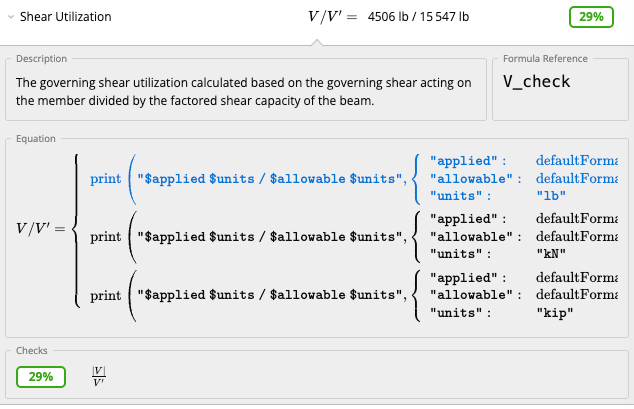
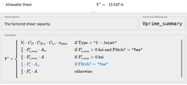
Open Shear Utilization and Allowable Shear in the Summary. For a flitch beam the Allowable Shear is V′=23Fv′AwV' = \tfrac{2}{3} F'_v A_w, the adjusted shear strength of the wood times the wood area. The steel plates do not add shear capacity.Shear Utilization with the description that the governing shear utilization is calculated from the governing shear divided by the factored shear capacity of the beam, and a result of 4506 pounds over 15 547 pounds at 29 percent.Allowable Shear of 15 547 pounds with the description the factored shear capacity, and an equation with two-thirds times the adjusted shear strength times the wood area highlighted for the case where Flitch is Yes.
4

See how bending capacity is set

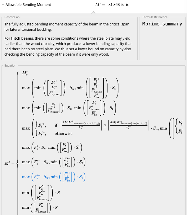
Open Allowable Bending Moment in the Summary. For a flitch beam, in some conditions the steel plate may yield earlier than the wood capacity, which gives a lower bending capacity than if there were no steel plate. The calculator sets a lower bound by also checking the bending capacity of the beam as if it were only wood.Allowable Bending Moment of 81 868 pound-feet with the description for flitch beams that the steel plate may yield earlier than the wood capacity, so a lower bound on capacity is set by also checking the beam as if it were only wood, and the equation with the wood section modulus and the transformed section modulus.
5

Look at the diagrams

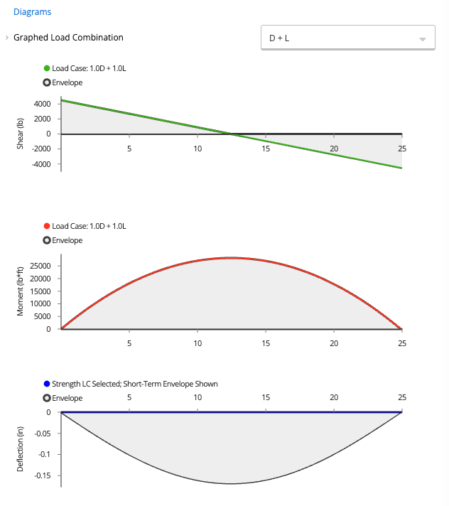
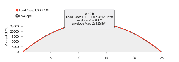
The Diagrams panel plots the shear, moment and deflection for the graphed load combination. The shear runs from about +4500 lb to −4500 lb, the moment peaks at about 28 000 lb·ft near mid-span, and the deflection is below the axis. Hover over a graph to read a value, for example 28 125 lb·ft at 12 ft.Diagrams panel with a shear graph from about 4500 pounds to minus 4500 pounds, a moment graph peaking near 28 000 pound-feet and a deflection graph below the axis with its lowest point near minus 0.17 inches.Loading diagram with vertical load arrows pointing down along the beam and reactions of 4506 pounds pointing up at each support.Moment graph with a tooltip at x of 12 ft reading a load case moment of 28125 pound-feet, with an envelope minimum of 0 and an envelope maximum of 28125 pound-feet.
Inputs, Calcs.com output and a hand check

Inputs

CalculatorWood Beam (ASD) NDS 2024
PresetGeneric Flitch Beam
Member5-1/2x16 24F-1.8E
Beam plan length LL25 ft
Flitch plates2, 0.375 in thick, 15.75 in deep
Yield strength FyF_y36 000 psi
Steel modulus EsE_s29.0 × 10⁶ psi
Adjusted wood modulus E′E'1.80 × 10⁶ psi

Calcs.com output

Modular ratio nn16.1
FbsF_{bs}, Fbs′F'_{bs}21 557 and 1338 psi
Load carried by steel67.7 %
MM, M′M'28 162 and 81 868 lb·ft
VV, V′V'4506 and 15 547 lb
Moment and shear utilization34 % and 29 %

Hand check

✓Modular ratio: n=Es/E′=29.0×106/1.80×106=n = E_s / E' = 29.0 \times 10^6 / 1.80 \times 10^6 = 16.1
✓Steel stress: Fbs=Fy/Ω=36 000/1.67=F_{bs} = F_y / \Omega = 36\,000 / 1.67 = 21 557 psi, and Fbs′=21 557/16.11=F'_{bs} = 21\,557 / 16.11 = 1338 psi
✓Steel area: As=nflitchtflitchdflitch=2×0.375×15.75=A_s = n_{flitch} t_{flitch} d_{flitch} = 2 \times 0.375 \times 15.75 = 11.8 in²
✓Transformed section modulus: St=npliesbd26+nflitchtflitchn dflitch26=5.5×1626+2×0.375×16.11×15.7526=234.7+499.6=S_t = \dfrac{n_{plies} b d^2}{6} + \dfrac{n_{flitch} t_{flitch} n\, d_{flitch}^2}{6} = \dfrac{5.5 \times 16^2}{6} + \dfrac{2 \times 0.375 \times 16.11 \times 15.75^2}{6} = 234.7 + 499.6 = 734 in³
✓Load carried by steel: EsIs/(E′Iw+EsIs)=29×244/(1.8×1877+29×244)=7076/10 455=E_s I_s / (E' I_w + E_s I_s) = 29 \times 244 / (1.8 \times 1877 + 29 \times 244) = 7076 / 10\,455 = 67.7 %
✓Uniform load from the reactions: w=2×4506/25=360.48w = 2 \times 4506 / 25 = 360.48 plf. Then V=wL/2=V = wL/2 = 4506 lb and M=wL2/8=360.48×252/8≈M = wL^2/8 = 360.48 \times 25^2 / 8 \approx 28 162 lb·ft
✓Allowable shear: V′=23Fv′Aw=23×265×88=V' = \tfrac{2}{3} F'_v A_w = \tfrac{2}{3} \times 265 \times 88 = 15 547 lb, with Fv′F'_v equal to the 265 psi Base Allowable Shear Stress in Member Properties, so V/V′=4506/15 547=V/V' = 4506 / 15\,547 = 29 %
✓Allowable moment, limited by the steel: M′=Fbs′St=1338×734.2/12=M' = F'_{bs} S_t = 1338 \times 734.2 / 12 = 81 863 lb·ft from the displayed values, and 81 868 lb·ft from the unrounded values, as the sheet shows, and M/M′=28 162/81 868=M/M' = 28\,162 / 81\,868 = 34 %

The modular ratio, the steel stresses, the section properties, the load shared by the steel, the shear and moment demands and the allowable shear match a hand calculation from the sheet’s formulas. The allowable moment agrees to within the rounding of the displayed values. This is a sanity check only. Wood Beam (ASD) NDS 2024 version 7.

Background

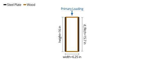
A flitch beam is a composite section made of one or more steel plates attached to a wood beam. They are typically used to reduce the structural depth of an equivalent wood-only beam. To account for the differing stiffness of the steel, the Flitch Beam Design panel calculates a modular ratio nn, the ratio of the elastic modulus of the steel to the adjusted modulus of elasticity of the wood, E′E': n=EsE′n = \frac{E_s}{E'} The Wood Beam (ASD) and Wood Beam (LRFD) calculators can add one or more steel flitch plates acting compositely with any wood section in the database or a custom section. Flitch plates are available only for strong axis (X-X) bending, and the diagram draws the plates parallel to the direction of the Primary Loading.

How to use it

1

Pick the preset

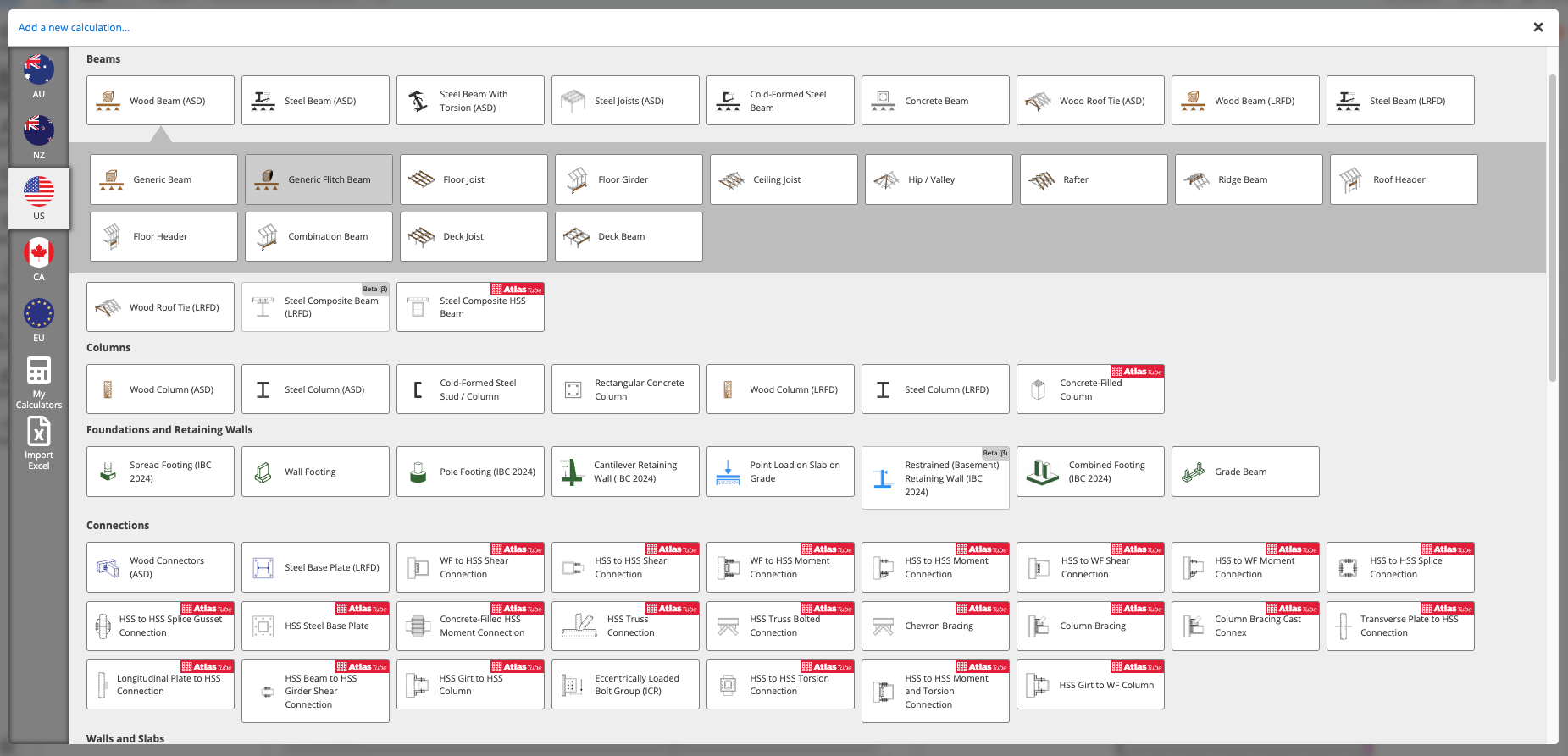
In Add a new calculation, open Wood Beam (ASD) on the US tab and choose the Generic Flitch Beam preset. Wood Beam (LRFD) has a Generic Flitch Beam preset too.Add a new calculation window on the US tab with Wood Beam (ASD) selected and its presets open, with Generic Flitch Beam highlighted.
2

Add flitch plates

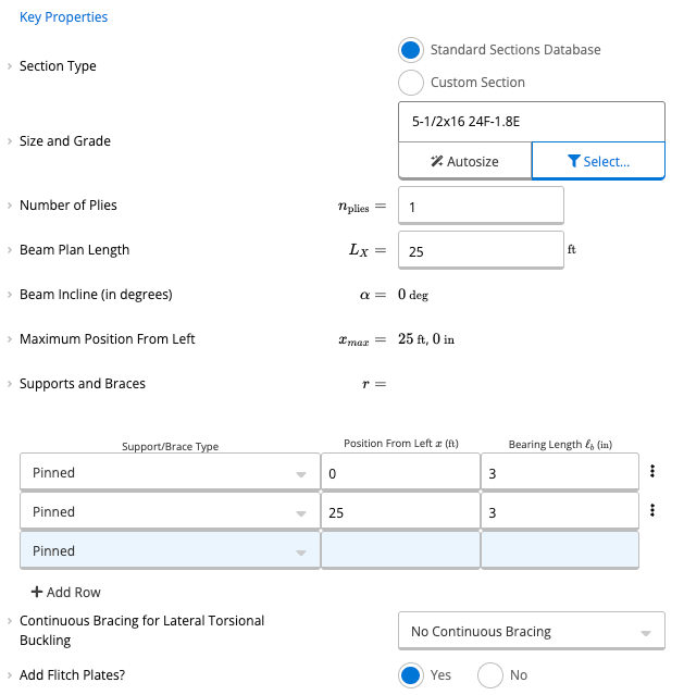
In Key Properties, set Add Flitch Plates? to Yes. It is available for strong axis bending only. The preset opens with a 5-1/2x16 24F-1.8E glulam member, a 25 ft beam plan length and pinned supports with a 3 in bearing length at each end.Key Properties with a Section Type of Standard Sections Database, a Size and Grade of 5-1/2x16 24F-1.8E, one ply, a Beam Plan Length of 25 ft, pinned supports at 0 and 25 ft with a 3 in bearing length, No Continuous Bracing and Add Flitch Plates set to Yes.
3

Enter the plates

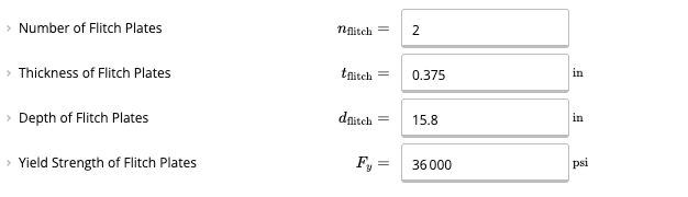
Enter the Number of Flitch Plates (at least 1), the Thickness of Flitch Plates for each plate, the Depth of Flitch Plates (usually the same depth as the member, and no more than it) and the Yield Strength of Flitch Plates (usually 36 ksi for A36 steel, or 50 ksi). The preset opens with 2 plates, each 0.375 in thick, with a depth 0.25 in less than the member depth (15.75 in, shown as 15.8 in the input and as 15.7 in on the section diagram) and a yield strength of 36 000 psi.Number of Flitch Plates 2, Thickness of Flitch Plates 0.375 in, Depth of Flitch Plates 15.8 in and Yield Strength of Flitch Plates 36 000 psi.The diagram draws the steel plates in black on the sides of the wood and shows the Primary Loading arrow pointing down.Diagram of the section with a legend of Steel Plate in black and Wood in brown, a Primary Loading arrow pointing down, a height of 16 in, a plate depth of 15.7 in and a width of 6.25 in with a steel plate on each side of the wood.
4

Check the steel modulus

In Member Properties, the Steel Modulus of Elasticity EsE_s is set to 29.0 × 10⁶ psi (29 000 ksi). You don’t enter it.Member Properties with the Base Allowable Bending Stress of 2400 psi, the Base Allowable Shear Stress of 265 psi, a Modulus of Elasticity for Deflections of 1.80 times 10 to the 6 psi, a Steel Modulus of Elasticity of 29.0 times 10 to the 6 psi and a Steel Shear Modulus of 11.2 times 10 to the 6 psi.
5

Review the Flitch Beam Design panel

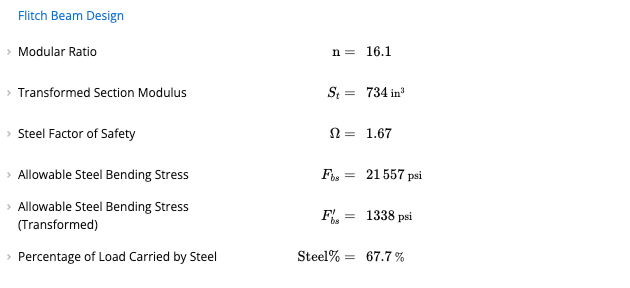
In Wood Beam (ASD), the Flitch Beam Design panel shows the Modular Ratio nn, the Transformed Section Modulus StS_t, the Steel Factor of Safety Ω\Omega, the Allowable Steel Bending Stress FbsF_{bs}, the same stress adjusted for the transformed section Fbs′F'_{bs}, and the Percentage of Load Carried by Steel. The allowable stress in the transformed section lets you compare the bending stress in the wood and the steel directly.Flitch Beam Design with a Modular Ratio of 16.1, a Transformed Section Modulus of 734 in cubed, a Steel Factor of Safety of 1.67, an Allowable Steel Bending Stress of 21 557 psi, an Allowable Steel Bending Stress (Transformed) of 1338 psi and a Percentage of Load Carried by Steel of 67.7 percent.

Connection design

The designer should also consider the connectors between the flitch plates and the wood beam. Calcs.com does not cover this detailing: the calculator has no connector inputs and does not size bolts, lag screws, spacing or edge distances. You can use the results to get the loading data on the flitch beam, from the Reactions diagram in the Summary, which lists the maximum and minimum factored reaction and the dead and live loads at each support, and from the Diagrams panel. Where the joists (members spanning into the beam) frame into the side at regular spacing, you may design for the connectors to handle a proportion of the load as shear perpendicular to the grain of the wood beam.

Shear check scope

The shear result in Wood Beam ASD and Wood Beam LRFD (with flitch plates enabled) is a standard NDS wood shear capacity check, not a connector or interface-shear check. When flitch plates are used, the calculator assumes shear and bearing are carried entirely by the wood section. Steel plates do not contribute to shear capacity. Governing shear demand is compared to allowable wood shear based on the gross wood area (AwA_w) and the adjusted allowable shear stress per NDS, as in the Allowable Shear formula above. The transformed-section method (modular ratio n=Es/E′n = E_s / E') is used for bending and steel stress checks only. It is not used to size plate-to-wood connectors or to compute interface shear between steel and wood.
The calculator does not size or detail flitch connectors (bolts, lag screws, spacing, or edge distances). Connector design must be done separately; see Connection design above for how to use loading output from the beam calculator.

Why a shear flag can still appear with direct end bearing

If the steel plate bears directly on steel or masonry at the supports, you may still see a shear utilization flag. That is expected: the check is always wood shear capacity along the span, independent of how the ends are detailed. End bearing and connector design at supports still need separate assessment. A direct-bearing detail at the ends does not change the wood shear check reported for the beam.

Common questions

No. For a flitch beam the Allowable Shear is two-thirds of the adjusted shear strength of the wood times the wood area, 23Fv′Aw\tfrac{2}{3} F'_v A_w. The plates are used for bending only.
The sheet’s description says it is usually 36 ksi for A36 steel, or 50 ksi. Enter it in psi, for example 36 000 psi.
E′E' is the adjusted modulus of elasticity of the wood, used to calculate deflections. For glulam it is the Modulus of Elasticity for Deflections EE in Member Properties multiplied by the wet service factor CMC_M and the temperature factor CtC_t. In the worked example E′E' and EE have the same value, 1.80 × 10⁶ psi.
No. The check on Add Flitch Plates? allows flitch plates only for strong axis (X-X) bending.
It uses the transformed section. The allowable steel bending stress Fbs=Fy/ΩF_{bs} = F_y / \Omega is divided by the modular ratio nn to give Fbs′F'_{bs}, and the capacity uses the lower of the adjusted wood bending stress and Fbs′F'_{bs} with the transformed section modulus. It also checks the beam as if it were only wood and uses that as a lower bound.

References

  1. National Design Specification for Wood Construction (NDS 2024), including Cl. 3.4 for shear
  2. AISC 360-16, Cl. F1.(a) for the steel factor of safety and Cl. F11 for the allowable steel bending stress

Next steps

Design a Wood Beam (ASD) to NDS 2024

Design wood beams to NDS 2024 (ASD): bending, shear, bearing and three deflection limits, with multi-ply and flitch plate options.

Design a Wood Beam (LRFD) to NDS 2024

NDS 2024 LRFD wood beam: bending, shear, bearing, three deflection checks with conversion and time effect factors. Multi-ply, flitch plate, inclined.

US Wood Beam: Interpreting & Optimizing Results

Read the four wood beam checks (bending, shear, deflection and bearing) in Calcs.com and find ways to optimize the design.