

United StatesTMS 402/602-22

Design partially- or fully-grouted reinforced CMU gravity walls to the current TMS 402/602-22 ASD. Out-of-plane shear and combined axial-bending interaction checks with a visual interaction graph across all ASCE 7 load combinations. Load reactions link to footing calculations.
Method & scope
Choosing the right calculator
Calcs.com has three TMS 402/602-22 masonry wall calculators. They are not interchangeable.Gravity Wall (LRFD)
Out-of-plane loading on a load-bearing wall span, checked per linear foot using LRFD.
Gravity Wall (ASD)
This page. Same out-of-plane problem using allowable stress design (TMS Chapter 8).
Shear Wall (LRFD)
In-plane lateral force-resisting walls with multi-story geometry and optional openings.
When to use this calculator
Use this calculator when you have a load-bearing CMU wall that must resist out-of-plane lateral loading in addition to gravity, and your project uses allowable stress design. If your project uses LRFD rather than ASD for masonry walls, use Masonry Gravity Wall (LRFD) for the same out-of-plane problem.Assumptions and limitations
- Wall is load-bearing, single-wythe, and CMU is in running bond.
- Wall is partially or fully grouted with one row of reinforcement centered in the block width.
- Bottom support is continuous (not spanning between point supports).
- Calculations are per linear foot of wall length. Walls shorter than 1 ft are not supported.
- Deflection criteria are not evaluated. TMS 402-22 Chapter 8 does not include deflection provisions for ASD masonry wall design.
- Fully grouted walls do not apply the slenderness limit, consistent with examples in MDG 2022.
- Stability checks for wall foundations are not conducted.
Full assumptions and limitations are listed in the Sheet Details tab within the calculator.
How to read the sheet: enter inputs first, review calculations in Detailed view, then read pass/fail in the Summary on the right.
Calculations
After inputs are set, the calculator builds section properties, applies ASD load combinations, and checks shear and moment-axial interaction. Open Detailed view to see intermediate steps and TMS 402/602-22 clause references for each section below.Design Conditions
Design Conditions pulls the load combination code from project defaults (IBC 2024 / TMS 402/602-22) and confirms the design standard edition in use.Key Properties
Key Properties computes derived section values used in the checks below: net area, moment of inertia, section modulus, radius of gyration, steel area, and Slenderness Ratio. Summary rows Maximum Axial and Maximum Allowable Axial Considering Slenderness Effects compare compression demand to slenderness-reduced allowable capacity. The slenderness limit applies when Fully or Partially Grouted? is set to partially grouted. Fully grouted walls skip this check per the template assumptions.Load Combinations (ASCE 7)
Load Combinations (ASCE 7) expands all ASD strength combinations and reports combined demands for moment, axial, and shear at the governing location. The finite-element beam model in the background uses Position of Supports & Braces from Bottom to build the analysis case.Out-of-Plane Shear (TMS 402-22, Section 8.3.5.)
Out-of-plane shear is checked in Out of Plane Shear. Summary rows Maximum Out of Plane Shear and Maximum Allowable Shear report the governing result. Bar Spacing (c/c) does not feed the shear strength calculation.Moment-Axial Interaction (TMS 402-22, Section 8.3.4.)
Combined axial and bending capacity is evaluated through Out of Plane Bending + Axial Interaction Table. The calculator builds separate tables for partially grouted and fully grouted walls per MDG 2022 Chapter 11.4.4. The Interaction Utilization Check table reports the utilization ratio for every load combination. Summary row Interaction Governing Utilization reports the highest value across combinations.All detailed calculation sections
All detailed calculation sections
- Key Properties
- Load Combinations (ASCE 7)
- Out of Plane Shear (TMS 402-22, Section 8.3.5.)
- Out of Plane Bending + Axial Interaction Table (TMS 402-22, Section 8.3.4. and MDG 2022 Ch.11.4.4)
Calculation method
Masonry and reinforcement properties
Material inputs establish the design basis: CMU block size (6” to 12”), masonry type (clay or concrete), specified compressive strength f’m, unit weight, and mortar type. Grout condition, partial or full, determines the effective cross-section used for all capacity calculations. Partial grouting uses the net area and net moment of inertia at the reinforced cell spacing; full grouting uses the gross section. Reinforcement is modeled as a single centered layer, with grade and bar spacing as inputs.Load combinations (ASCE 7)
ASD load combinations per ASCE 7 are assembled and the governing case for axial and for out-of-plane bending is identified. Wind and seismic lateral pressures are applied as distributed loads per 1 ft of wall width. The calculator evaluates all applicable combinations and flags the governing demand for each check.Out-of-plane shear (TMS 402-22, Section 8.3.5)
Applied shear demand from out-of-plane lateral loads is compared to the allowable masonry shear stress: fv ≤ Fv where Fv is a function of f’m and grout condition per Section 8.3.5. In-plane shear is not checked, this calculator is for gravity walls only, not shear walls.Out-of-plane bending and axial interaction (TMS 402-22, Section 8.3.4, MDG 2022 Ch.11.4.4)
Combined axial and bending demands are checked against the allowable interaction envelope. For each applied axial load P, the allowable moment Ma is computed from the ASD provisions and the interaction ratio evaluated: P / Pa + M / Ma ≤ 1.0 The interaction graph plots the full capacity envelope and demand points from all governing load combinations. Adjusting bar size, spacing, or grout condition immediately updates the graph to confirm the revised configuration. Deflection checks are not included, Section 8 of TMS 402-22 does not contain deflection limits for ASD masonry walls. The fully grouted wall model does not apply the slenderness limit per MDG 2022 examples.How to use it
1
Inputs
Work through the input sections in order. Geometry, reinforcement, and loads drive all downstream checks.
1
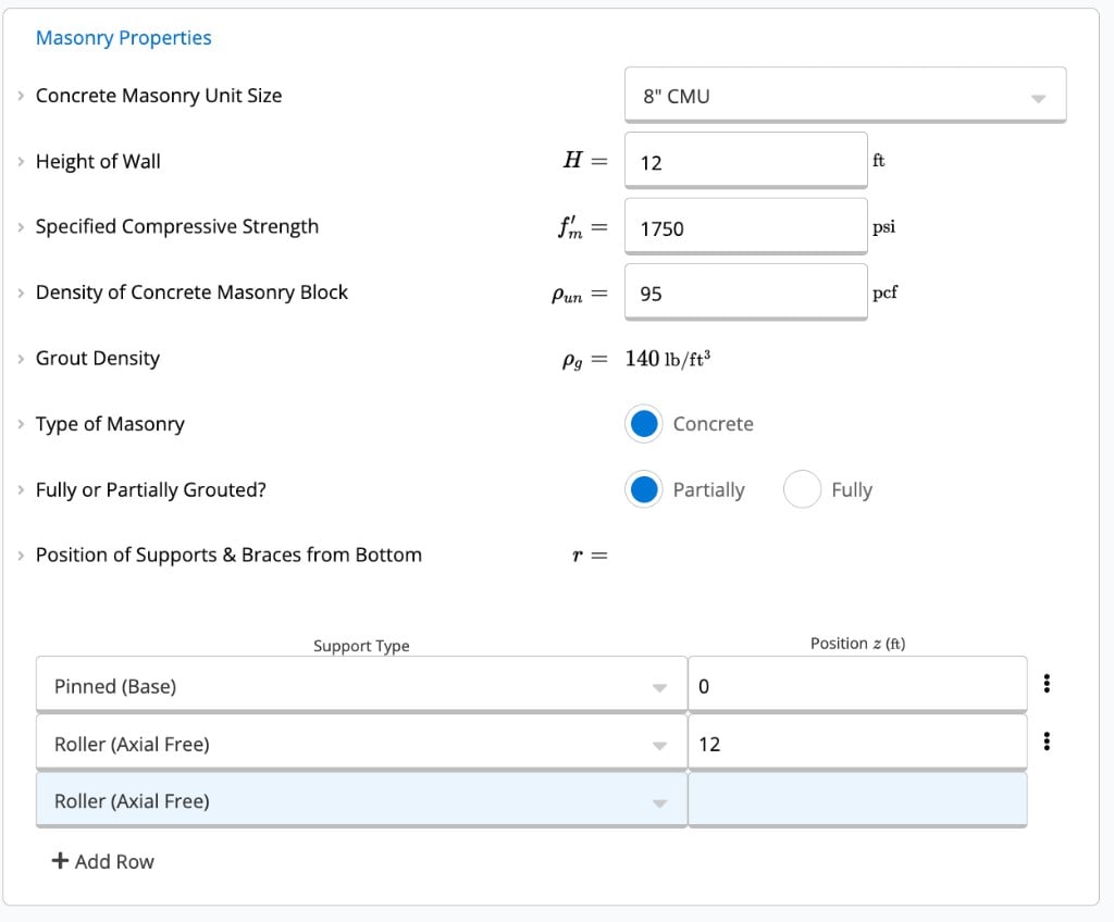
Masonry Properties
These inputs feed wall geometry, material strength, and support conditions in Key Properties, self-weight, slenderness, and the interaction diagram.
- Concrete Masonry Unit Size: nominal block width (6”, 8”, 10”, or 12”). Section properties follow CMU-TEC-002-23.
- Height of Wall: clear span between supports. Sloped walls are not supported.
- Specified Compressive Strength: design compressive strength of the masonry assembly, typically 1500 to 2500 psi.
- Density of Concrete Masonry Block and Grout Density: feed the Self-Weight output in Key Properties.
- Fully or Partially Grouted?: switches between partially and fully grouted section properties, interaction tables, and whether the slenderness limit appears in Summary.
-
Position of Supports & Braces from Bottom: support types and heights from the bottom of the wall. Used by the beam analysis model in Load Combinations (ASCE 7).
2
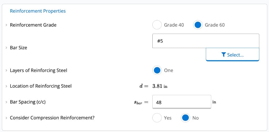
Reinforcement Properties
Reinforcement is assumed in a single centered row.
- Reinforcement Grade, Bar Size, and Bar Spacing (c/c): feed steel area and moment capacity in Out of Plane Bending + Axial Interaction Table. Default spacing is six times the nominal block width. The calculator may flag spacings that do not align with the block module.
-
Consider Compression Reinforcement?: toggles whether tied compression steel is included in Maximum Allowable Axial Considering Slenderness Effects per TMS 402/602-22 Section 8.3.4.2.1.
3
Loads
Enter unfactored (service) loads. The calculator applies ASD load combination factors in Load Combinations (ASCE 7).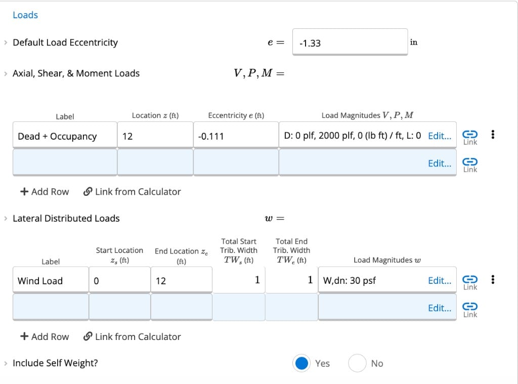
- Default Load Eccentricity: default axial eccentricity for bending, taken as one sixth of the block depth. Override per load in the Axial, Shear, & Moment Loads table.
- Axial, Shear, & Moment Loads: line loads per foot of wall. Each row can set its own eccentricity and load types (D, L, W, E, and others).
- Lateral Distributed Loads: area loads converted to line loads using tributary width. Default wind entries populate from project defaults when available. Specify different tributary widths at the start and end of a load to enter triangular distributions.
2
Results
The Summary panel on the right collects governing pass/fail outcomes. The Out of Plane Bending + Axial Interaction Diagram at the top of the sheet plots the moment-axial capacity envelope alongside each load combination.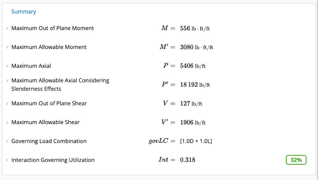
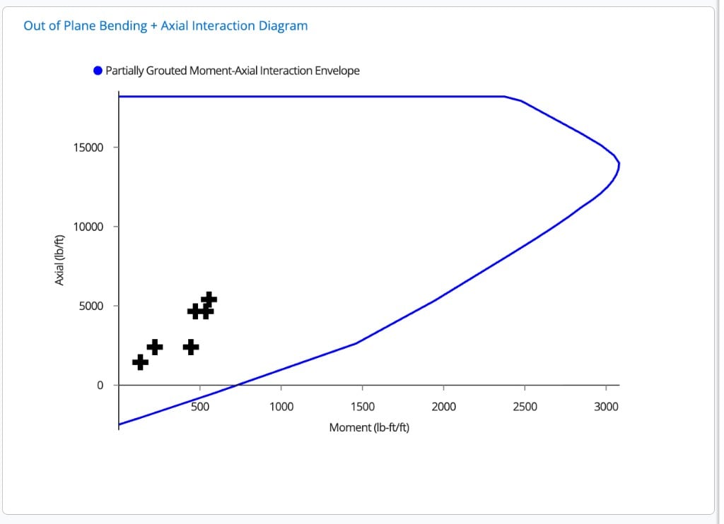
Out-of-plane moment
Maximum Out of Plane Moment vs Maximum Allowable Moment
Axial compression
Maximum Axial vs Maximum Allowable Axial Considering Slenderness Effects
Out-of-plane shear
Maximum Out of Plane Shear vs Maximum Allowable Shear
Interaction
Interaction Governing Utilization and Governing Load Combination
Switch to Detailed using the toggle at the top of the calculator to see every intermediate step and the relevant TMS 402-22 clause for each check.
A reinforced CMU gravity wall carries vertical loads while resisting out-of-plane forces from wind or seismic pressure. This calculator checks moment, axial, and shear capacity using allowable stress design per TMS 402/602-22 Chapter 8. It supports partially and fully grouted single-wythe walls and plots a moment-axial interaction diagram for each design.
This calculator follows TMS 402/602-22 Chapter 8 (ASD) and MDG 2022 Chapter 11.4.4 for interaction tables. Load combinations follow ASCE 7 ASD provisions.
Troubleshooting
Inputs flagged in red
Inputs flagged in red
Check the validation message next to the field. Common causes include bar spacings that are not practical multiples of the block module and compressive strength values outside the supported range.
Interaction check fails in Summary
Interaction check fails in Summary
Open Out of Plane Bending + Axial Interaction Table in Detailed view to see utilization per load combination. Check whether Eccentricity on individual load rows or Fully or Partially Grouted? is driving the result. Summary row Governing Load Combination identifies which combination controls.
One check is governing in Summary
One check is governing in Summary
Open that check in Detailed view to see which inputs feed the calculation. Summary rows link to the governing section. Use the input list above to find the corresponding fields in the sheet.
Common questions
What design method and code standard does this calculator use?
What design method and code standard does this calculator use?
Allowable Stress Design (ASD) per TMS 402/602-22, the current code edition. TMS 402/602-22 was formerly designated ACI 530, ACI 530.1, ASCE 5, and ASCE 6. All section references in this calculator are to the 2022 edition.
What are the key inputs?
What are the key inputs?
CMU block size, masonry type (clay or concrete), specified compressive strength (f’m), unit weight, grout condition (partial or full), bar size and spacing, wall height, boundary conditions, axial gravity loads, and out-of-plane wind or seismic distributed loads.
What does it check or output?
What does it check or output?
Out-of-plane shear (TMS 402-22, Section 8.3.5) and combined axial-bending capacity across ASCE 7 load combinations. Results include an interaction graph showing allowable axial versus bending capacity with demand points plotted for each load combination.
Can it handle both partially and fully grouted walls?
Can it handle both partially and fully grouted walls?
Yes, partial and full grouting are both supported. Net section properties (area, moment of inertia) adjust automatically based on the grout condition and reinforcement spacing. The fully grouted wall analysis does not apply the slenderness limit per MDG 2022 examples.
How is this different from the TMS 402/602-16 version?
How is this different from the TMS 402/602-16 version?
This calculator uses TMS 402/602-22 section references for out-of-plane shear (Section 8.3.5) and bending (Section 8.3.4). Use the newer version for new projects and the TMS 402/602-16 version only for projects originally designed under that code edition.
Does this calculator support load linking with footing calculations?
Does this calculator support load linking with footing calculations?
Yes, axial reactions at the wall base can be linked directly to footing calculations in the same project. Changing gravity loads in a connected beam or column automatically updates the wall’s axial demand and the footing below.