

All regions

Solve 2D trusses with a live FEA engine. Set nodes, fixities, and members in-browser, and get shear, moment, and deflection results as you work. Covers roof, floor, and custom truss geometries with nothing to install.
Worked example
A roof truss is to be designed in Australia. The calculation details of this worked example can be found here.-
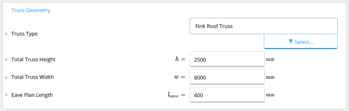
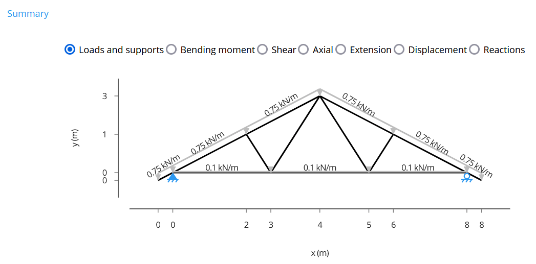
Fink Truss type with 8 meters wide, 2.5 meters height, and a 400 millimeter overhang. Please check the diagram in Summary section to confirm the dimensions.\
-
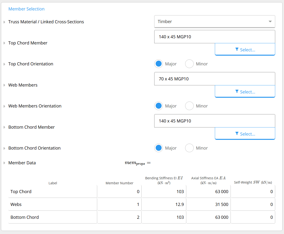
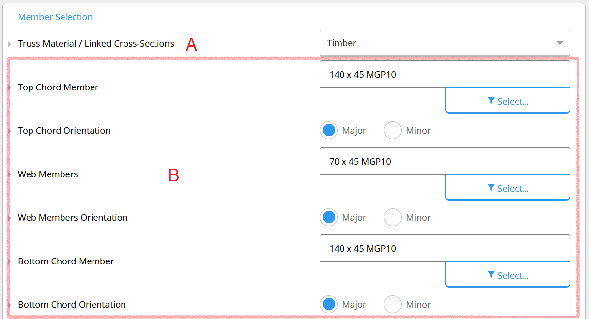
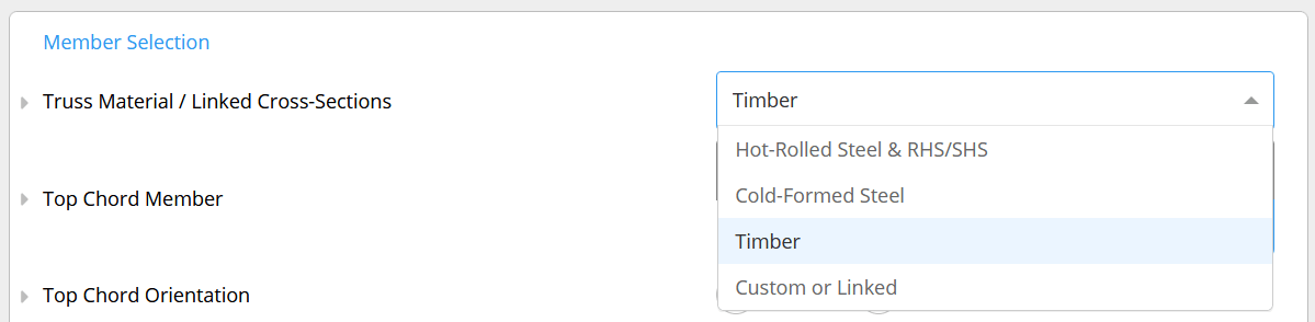
Timber components, with both top and bottom chords 140x45 MGP10, and web members 70x45 MGP10, all oriented about their major axes. Note that if you change the member orientation, the bending stiffness (EI) in the table Member Data is updated.\
-
Factored dead plus live load of 0.7 kN/m on the top chords, and a factored ceiling dead load of 0.1 kN/m on the bottom chord (vertical loads). You can check the diagram under the Summary section to confirm if the loads are correctly applied.\
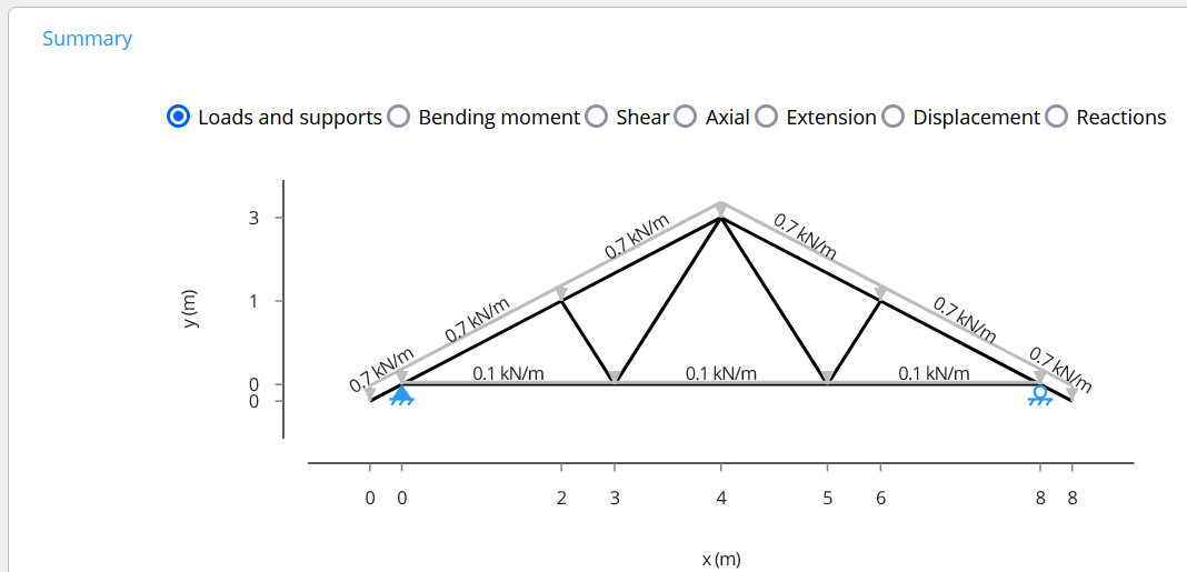
- Factored wind load of 0.45 kN/m on the top chords
-
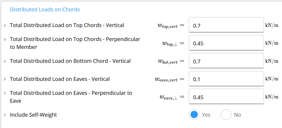
 The figure below shows the load table, don’t forget to check Yes for including self-weight.
- Under Summary, you can check all results. For axial forces, for example, the results shown in the diagram are confirmed in the table Overall Results by Member Type.
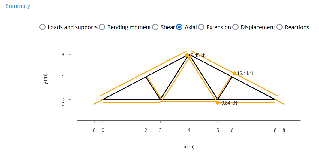
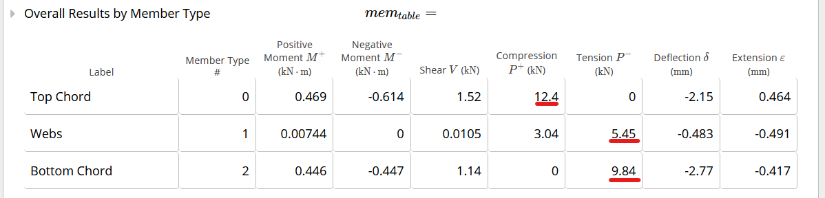
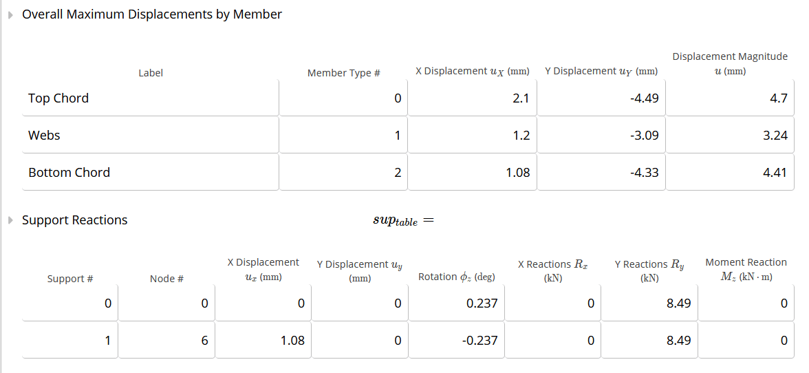
- The displacements and support reactions are also shown in diagrams and tables.
 \
\
Method & scope
Scope
The Calcs.com Truss Analysis calculator allows users to input the geometry of some common truss types and specify the load conditions on the truss. It then determines the cumulative load applied, support reactions, bending moment, shear and axial forces, extension and displacement for each chord of the truss. Component members of the truss may then be designed by creating a new “Design Only” calculation, and linking it to the truss analysis calculation. The sheet has 3 main input sections, plus the Summary results section:- Truss/Frame Geometry
- Member Selection
- Distributed Loads on Chords
- Summary
Calculation method
The Truss Analysis Wizard uses a direct stiffness finite element analysis (FEA) engine to solve any planar 2D truss. You define the geometry, node coordinates, member connectivity, support fixities, and loads, and the solver assembles and inverts the global stiffness matrix to return forces and displacements simultaneously across every member.Geometry and member modeling
Each member is modeled as a two-node axial bar element with user-specified cross-section area (A) and elastic modulus (E). The calculator supports a library of preset truss configurations, Flat Warren, Flat Pratt, Flat Howe, Flat Brown, King Post, Queen Post, Single Fan, Simple Fink, and Fink roof trusses, as well as fully custom node and element definitions. For non-custom configurations, straight chord regions are treated as continuous members rather than pin-jointed segments; this is more accurate but means results may differ slightly from a traditional hand analysis.Stiffness assembly and solution
The solver assembles the global stiffness matrix from the individual element stiffness contributions, applies boundary conditions at pinned and roller supports, and solves the resulting system of linear equations for nodal displacements. Member end forces are back-calculated from the displacements using the element stiffness relation.Sign conventions and outputs
- Positive bending moment indicates that the bottom or right side of the member is in tension.
- Positive axial load indicates a compressive load (compression-positive convention).
- Axial force, tension or compression demand in each member
- Shear force and bending moment envelopes along each element
- Nodal displacements and support reactions
Load application
Distributed loads can be applied to chord members. For preset configurations, loads are specified over the chord length; the FEA engine converts these to equivalent nodal contributions automatically. Advanced users can also apply loads directly by element number for non-standard cases. Multiple load cases are evaluated and an envelope of governing demands is reported.Linking to design calculators
The Truss Analysis Wizard is an analysis-only calculator. After solving, member force demands (moment, shear, axial) can be linked directly to Design Only calculators, such as timber, steel, or cold-formed steel beam calculators, so each member is checked against the relevant code without re-entering geometry or loads.How to use it
1
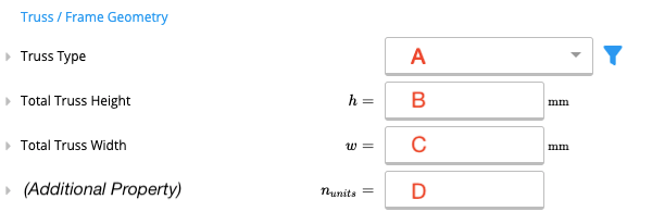
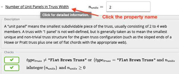
Truss/Frame Geometry
2
Member Selection



3
Distributed Loads on Chords
 A. Total Distributed LoadsFor the first two sections, the total vertical distributed loads for the top chord and bottom chord need to be specified in kN/m (or plf if you are using the Imperial unit system). Depending upon the type of truss selected, inputs may also be available for loads that are perpendicular to the top chord (not vertical i.e., gravity versus aligned loading conditions).Please note that the subsequent section “Advanced Loads (by Element Number)” can be used to enter loads for individual members, point loads, and angled loads - but most analyses should not require this.B. Self-WeightYou can choose whether or not to include the self-weight of the truss in calculations. The default has been set to include the self-weight of the truss.
4
Summary
On top of the summary section is a diagram of your truss. The display of this diagram can be changed to show loads and supports, bending moment, shear forces, axial forces, extension of members, displacement of members and reaction forces at supports. This feature is illustrated below.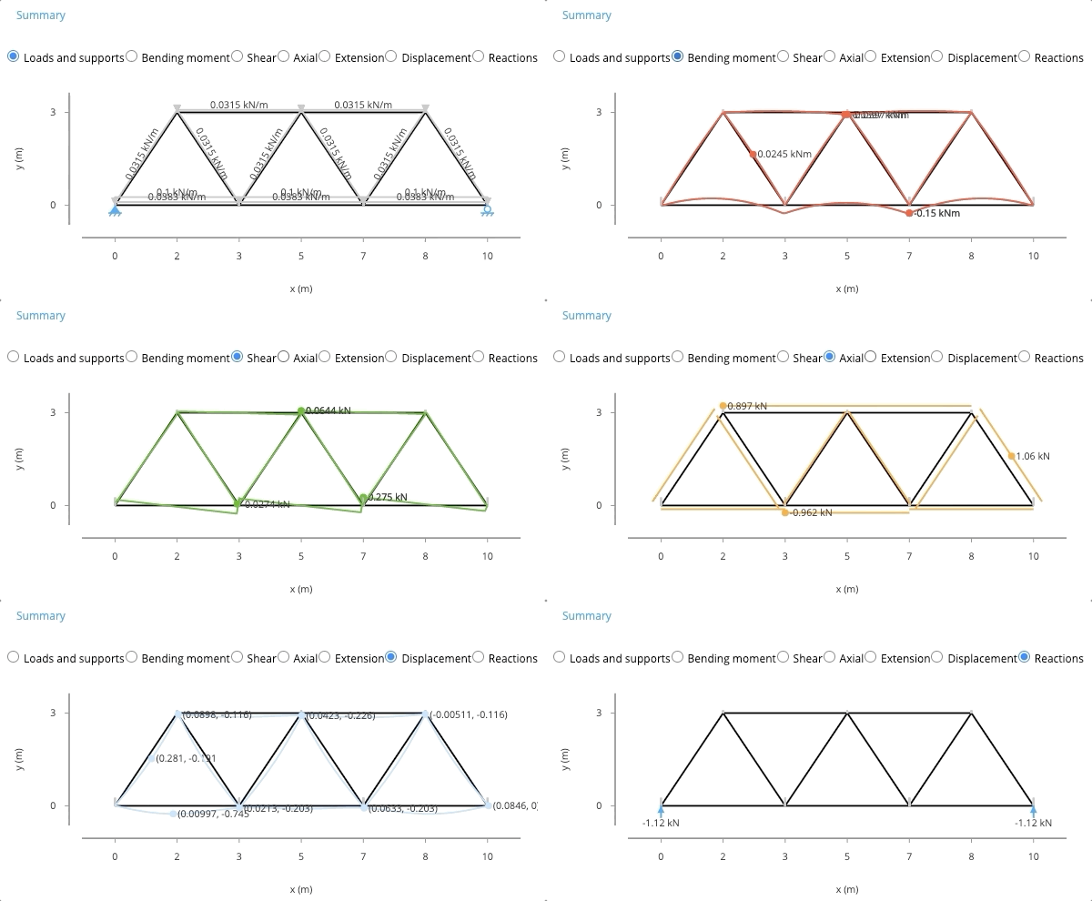
5
Designing Components by Linking New Calculators
Typically, once a truss is analyzed, the components will also need to be designed. This may be done in Calcs.com by the following procedure:
- Select “Add New Calculation” in the left sidebar
- Add a “Design Only” calculator for the appropriate material (for example, “Timber Member (Design Only)”)
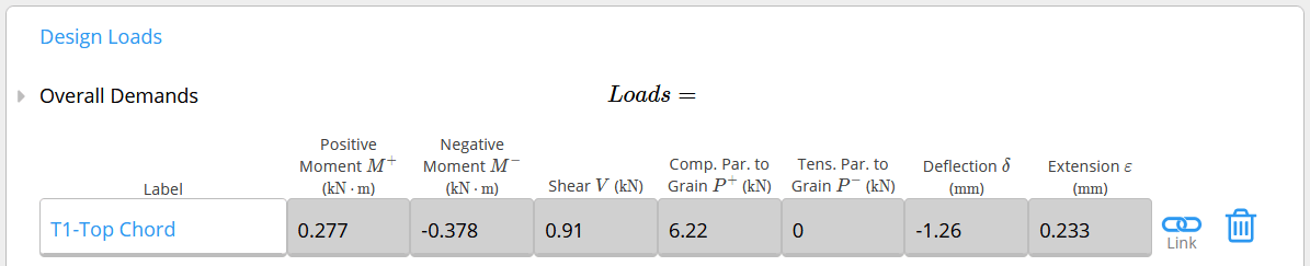
- Next to the loads table in this new calculator, click on Link

- In the modal that pops up, select the truss analysis calculation, and then the component of the truss you wish to design (for example, “Top Chord”)
 \
\
- Complete the rest of the design as normal, referring to the help documentation for the specific material.
Common questions
What analysis method does this calculator use?
What analysis method does this calculator use?
The Truss Analysis Wizard uses a direct stiffness finite element analysis (FEA) engine. Each truss member is modeled as a two-force axial element. The solver assembles the global stiffness matrix, applies boundary conditions at pinned and roller supports, and solves for nodal displacements and member forces simultaneously.
What are the key inputs?
What are the key inputs?
Key inputs are node coordinates (x, y), member connectivity (start node, end node), support fixity at each node (pinned, roller, or free), member cross-section area and elastic modulus, and applied nodal loads (force magnitude and direction). You can define any planar truss geometry, roof, floor, Pratt, Howe, or fully custom layouts.
What does the calculator output?
What does the calculator output?
Outputs include axial force in every member (tension or compression), nodal displacements, and support reactions. Force diagrams and displacement plots update live as you edit geometry or loads. Results are printable in a structured report for submission or record-keeping.
Can I model multi-bay or non-standard truss geometries?
Can I model multi-bay or non-standard truss geometries?
Yes. The calculator is geometry-agnostic, nodes can be placed anywhere in the plane, and members can connect any two nodes. This allows Pratt, Howe, Fink, Gambrel, arch, and multi-bay configurations. There is no limit on the number of nodes or members within the platform.
How do I handle distributed loads on top-chord members?
How do I handle distributed loads on top-chord members?
Distributed loads on chord members must be converted to equivalent nodal loads at the panel points before entry. Divide the distributed load by the panel spacing to get point loads at each intermediate node. For roof trusses under uniform snow or dead load, this means applying equal vertical forces at each top-chord node based on tributary length.
Next steps
Analyze a Portal Frame in Calcs.com
Analyze single- or multi-bay 2D portal frames with FEA. Flat, gable, arch and tied geometries, with moment, shear, axial and displacement results.
Design a Timber Member (Design Only) to AS 1720.1:2010 (Amdt 3)
Design timber truss chords, frame members and rafter ties to AS 1720.1:2010 (Amdt 3), with combined bending, axial and shear checks.
Create and Use a Custom Section in the Custom Truss Analysis
Learn how to build a custom truss layout, define member types, create a custom cross-section, and link it into the Custom Truss Analysis calculator.
Link Design Calculators to Truss & Portal Frame Analysis
Link Design Only calculators to Truss Analysis and Portal Frame Analysis results to check member capacity against the analysis forces.