

AustraliaAS3600:2018 (Amdt 2)

Footing loads link up to the columns and beams above, so structural changes propagate down automatically. Design concrete pad footings to AS 3600:2018 (Amdt 2) with instant moment, shear, and punching shear results.
The Concrete Pad Footing Calculator is a tool designed to simplify the design and analysis of concrete pad footings. It ensures compliance with Australian Standard AS 3600:2018 and provides precise calculations for stability, moments, shears, punching shear, and bearing capacity. This guide explains the features, input requirements, and results generated by the calculator.
Method & scope
Eccentric Loading: The Central Challenge
One of the most critical aspects of footing design is handling eccentric loads, when the column or applied load does not act through the center of the footing. Eccentricity creates uneven stress distributions, leading to higher stresses on one side of the footing. This can reduce soil contact and increase risks of overturning or bearing failure. The calculator evaluates eccentricity:- Effective Eccentricity (e) is calculated using the applied moment and column offsets.
- Stress Distribution and Bearing Length (Le) adjust dynamically to account for reduced soil contact
- Key Properties: Where the footing and column geometry, material properties, and load data are input.
- Summary Outputs: Displays calculated capacities, demands, and a stability assessment
1. Key Properties
This section is where all necessary design inputs are entered. Each property influences the footing’s structural behavior and the calculator’s results. Below are the main categories and their descriptions:Footing Geometry
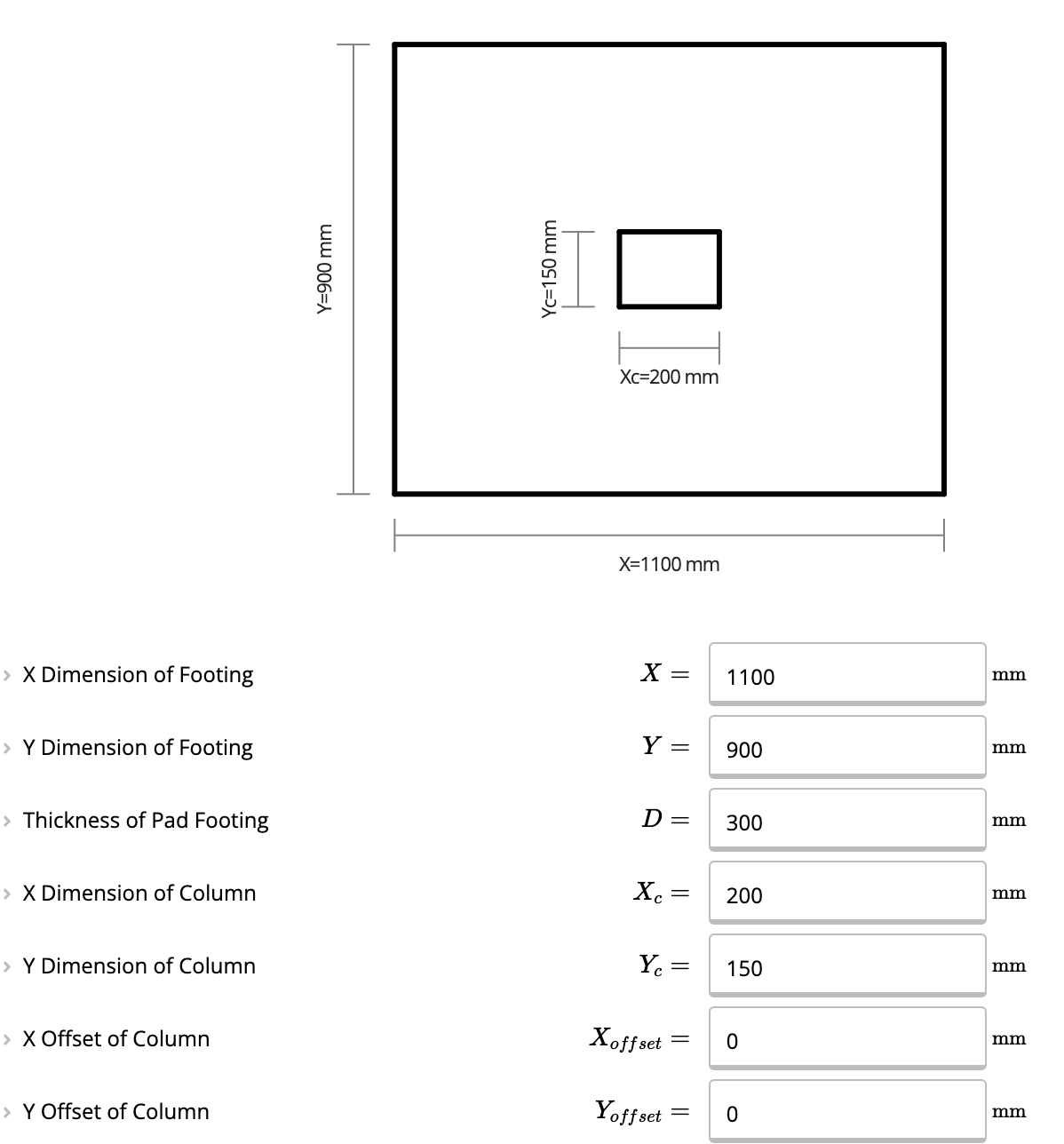
- X and Y Dimensions: The width and length of the rectangular footing. These dimensions must be greater than the column dimensions to provide adequate stability.
- Thickness (D): The depth of the footing, critical for shear and moment capacity.
- Column Dimensions (Xc, Yc): The width and length of the column supported by the footing.
- Column Offsets (X Offset, Y Offset): Specify eccentricity if the column is not centered, allowing for adjustments based on the direction of the applied moment.
Material and Soil Properties
- Concrete Strength and Type: Select the characteristic compressive strength (e.g., 32 MPa normal-weight concrete). It impacts the footing’s resistance to bending and shear.
- Unit Weight of Soil (γₛ): Defines the density of the soil surrounding the footing.
- Allowable Bearing Capacity (qₐ): The maximum pressure the soil can support without failure.
Reinforcement in Pad Footing
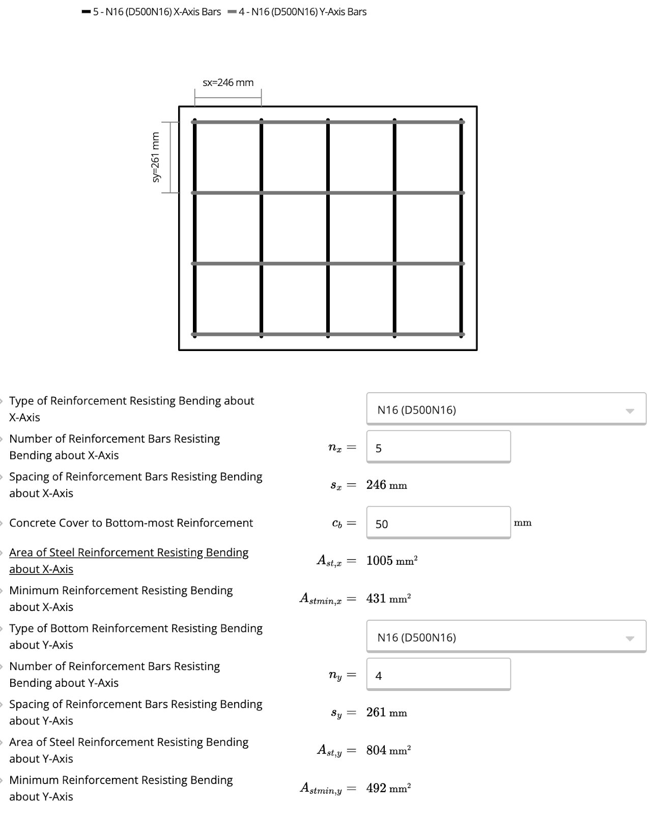
- X-Axis Reinforcement: Select the type of steel reinforcement bars (e.g., N16, N20) for resisting bending along the X-axis.
- Y-Axis Reinforcement: Choose the type of steel reinforcement bars for resisting bending along the Y-axis.
- Number of Bars (nx, ny): Specify the number of bars required for each axis.
- Concrete Cover (cb): Input the distance between the outer surface of the concrete and the nearest reinforcement. This ensures adequate protection against corrosion and complies with durability requirements.
Applied Loads
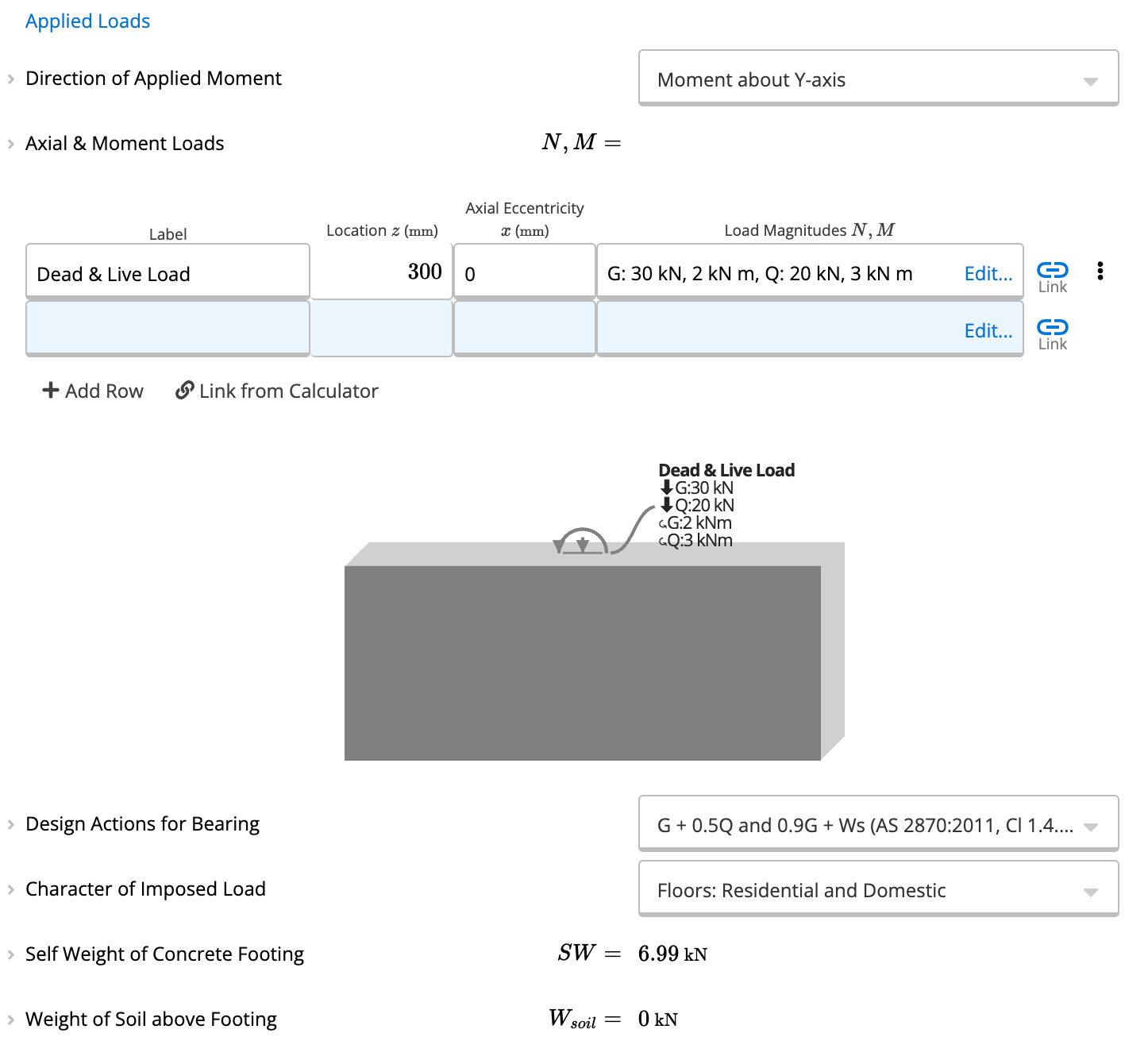
- Direction of Applied Moment: Specify if the moment acts about the X-axis or Y-axis.
- Dead Load (G): Permanent forces, such as the self-weight of the structure, transferred to the footing.
- Live Load (Q): Transient or variable forces, such as occupancy or equipment loads.
- Moment Loads (M): Enter moments caused by eccentricity or lateral forces, which can lead to overturning or additional stresses on the footing.
Stress Distribution and Load Demands
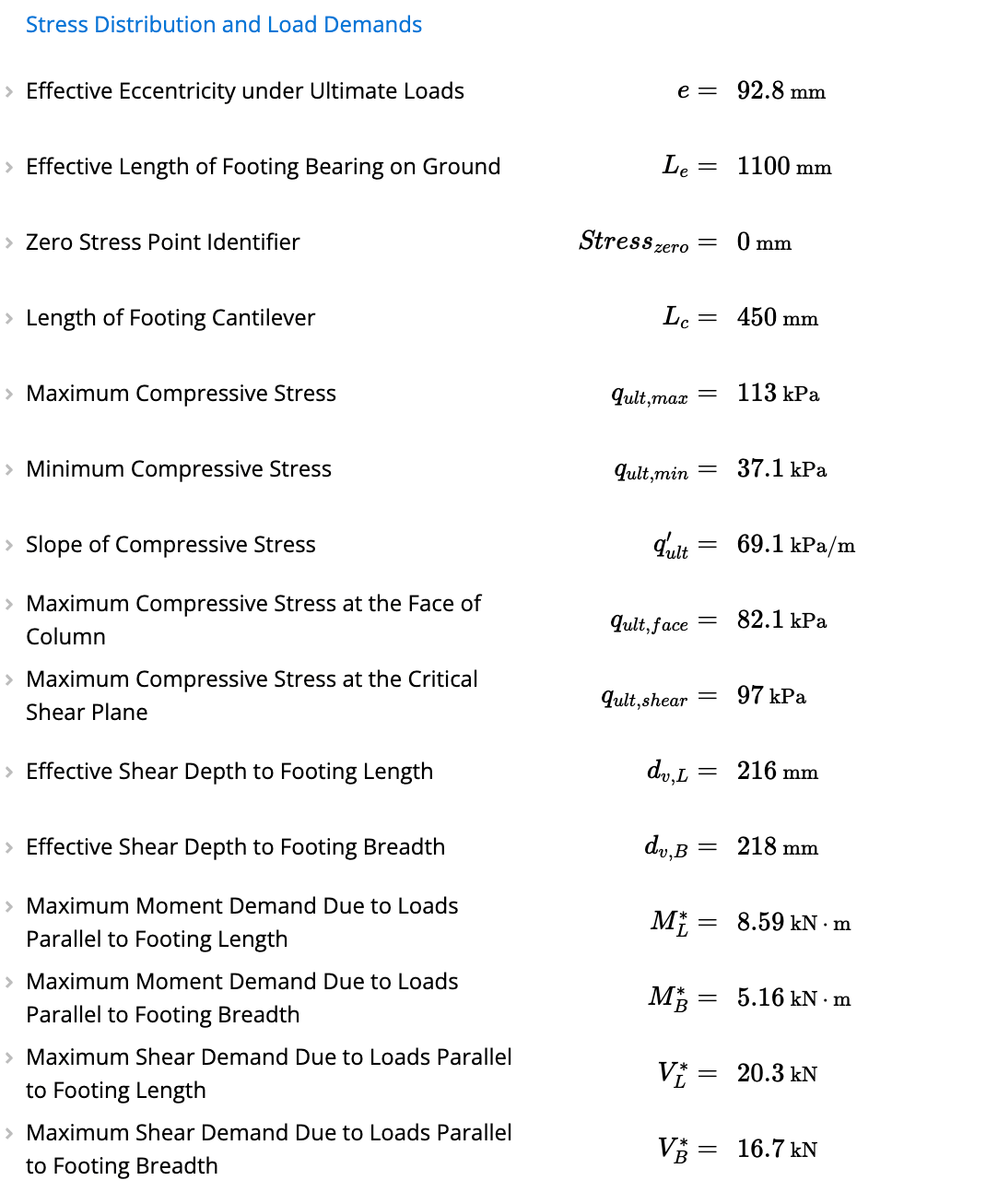
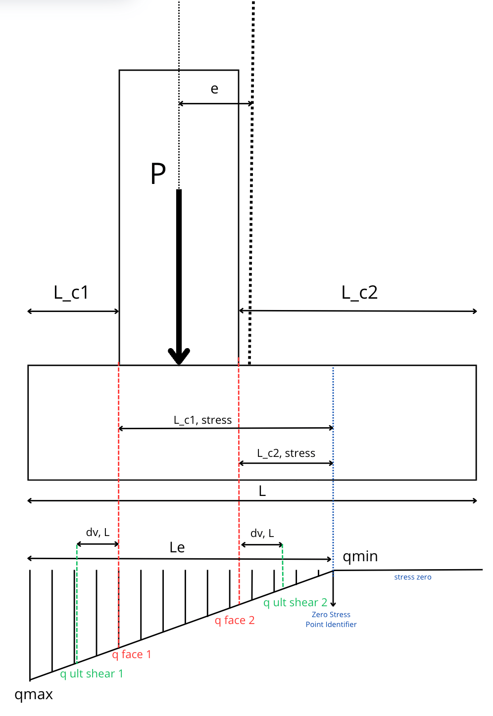
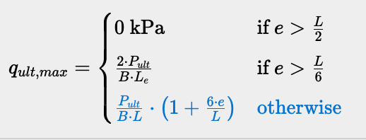
- Ensures proper stress transfer to the soil by reducing the effective bearing length in cases of high eccentricity.
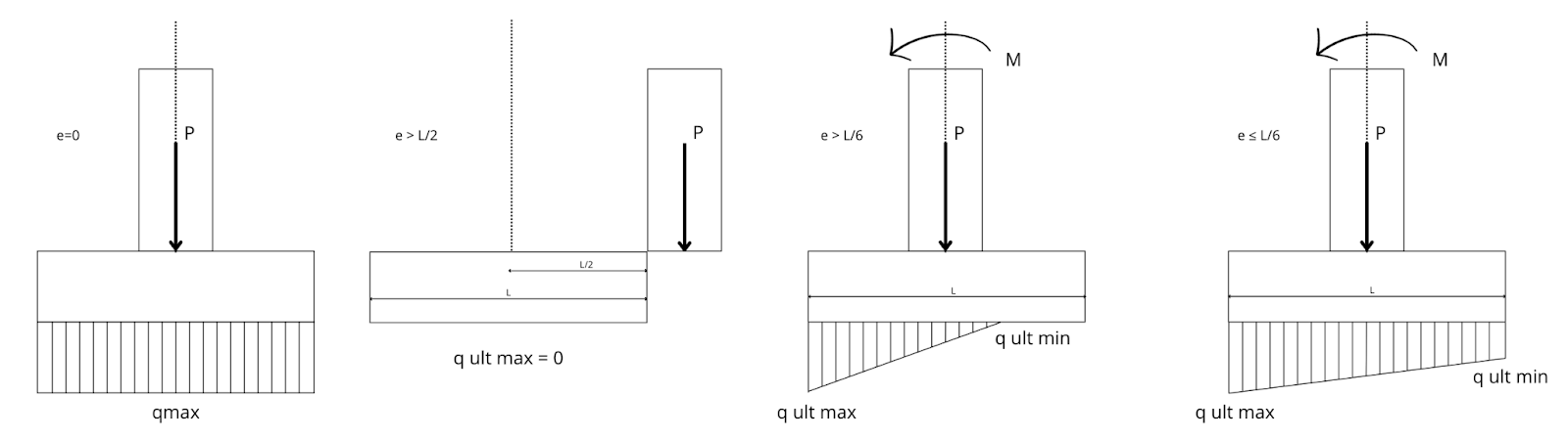
- Considering these conditions:
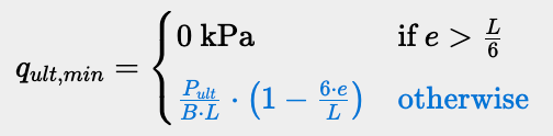

- Maximum compressive stress at both faces of the column(q,ult,face1, q,ult,face2): Are the compressive stresses at the two opposite faces of the column (e.g., left/right or bottom/top).The stress at these faces depends on the eccentricity and load distribution.
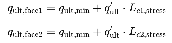
- (dv,L) refers to the depth of the footing that actively resists shear forces parallel to its length (X-axis).
- (dv,B) refers to the depth of the footing that resists shear forces parallel to its breadth (Y-axis).

- (): The highest bending moment experienced by the footing along its length (X-axis) due to applied loads and stress distribution.
- (): The highest bending moment experienced by the footing along its breadth (Y-axis), due to applied loads and stress distribution.
- (): The highest shear force acting along the footing’s length (X-axis) due to applied loads and stress distribution.
- (): The highest shear force acting along the footing’s breadth (Y-axis).
2. Summary
The Summary section consolidates all the critical design parameters and results generated by the calculator. It provides engineers with a quick and actionable overview of the footing’s performance against various structural and geotechnical criteria. These results ensure compliance with AS 3600:2018 and help verify the adequacy of the design.-
Moment Demand and Capacity:
- Moment Demand about X-axis (Mx): This represents the design moment acting about the X-axis, calculated at the critical section of the footing based on the applied loads, eccentricities, and moments.
- Moment Demand about Y-axis (My): This is the corresponding design moment about the Y-axis, similarly derived from the loads and eccentricities along this axis.
- Moment Capacity about X-axis (ϕMu,x): This is the maximum moment strength the footing can resist about the X-axis, determined based on reinforcement and concrete strength.
- Moment Capacity about Y-axis (ϕMu,y): The moment capacity about the Y-axis, similarly derived. Any instance where demand exceeds capacity is flagged by the calculator.
-
Shear Demand and Capacity:
- Shear Demand about X-axis (Vx): The highest shear force acting along the X-axis of the footing, typically at a critical section near the column.
- Shear Demand about Y-axis (Vy): The highest shear force acting along the Y-axis.
- Shear Capacity about X-axis (ϕVu,x): This is the maximum shear strength the footing can resist along the X-axis.
- Shear Capacity about Y-axis (ϕVu,y): The corresponding shear strength along the Y-axis. If demand exceeds capacity for either axis, it is flagged for review.
-
Punching Shear:
- Punching Shear Demand (V): This is the vertical force acting around the column interface, evaluated along the critical punching shear perimeter. It accounts for load concentrations that could lead to failure.
- Punching Shear Capacity (ϕVu): This represents the footing’s ability to resist punching shear, based on its thickness, reinforcement, and material properties. Exceeding this capacity triggers a redesign.
-
Stability Check:
- Limited Stability Check: This output determines whether the footing remains in total compression under service loads. The stability status can be:
- Stable: The footing remains fully compressed under working loads, ensuring no loss of soil contact.
- Partial Compression: Part of the footing disengages from the soil, increasing the risk of overturning or rotation.
- Unstable: The footing becomes unstable, signaling a significant design failure.
- Limited Stability Check: This output determines whether the footing remains in total compression under service loads. The stability status can be:
-
Bearing Stress and Capacity:
- Maximum Bearing Stress (qmax): This is the maximum compressive stress experienced at the footing edge due to the applied loads.
- Bearing Capacity of Footing Soil (qb): The maximum pressure the soil can sustain safely. If qmax exceeds qb, the calculator highlights this as a failure.
-
Graphical Load Case Visualization:
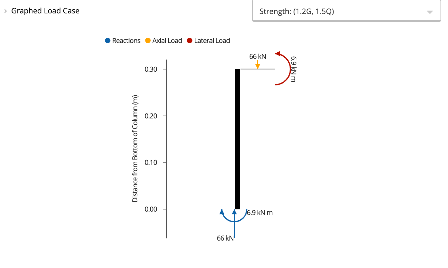
- The load case visualization provides a clear graphical representation of the applied loads, moments, and reactions. Each load case evaluates a different aspect of the footing’s performance:
- Strength Load Cases ensure the footing remains safe under extreme conditions.
- Serviceability Load Cases verify that the footing performs well during normal operation, with minimal settlement or cracking.
- Geotechnical Load Cases confirm that the soil can safely support the applied loads without excessive deformation or failure.
Calculation method
The Concrete Pad Footing calculator designs square or rectangular reinforced concrete pad footings to AS 3600:2018 (Amendment 2). It checks bending, one-way shear, and punching shear in both plan directions, and verifies bearing pressure under service loads.Geometry and inputs
The footing is modeled as a rectangular slab of plan dimensions X × Y and thickness D, with a rectangular column of dimensions X_c × Y_c centered on the footing. Soil depth above the footing (d_soil) and column offset from the centroid can also be specified.Load distribution and bearing check
Applied column loads (axial force N, biaxial moments M_x and M_y, and shear) are resolved into a non-uniform bearing pressure distribution across the footing plan. The maximum bearing stress q_max is compared to the allowable bearing capacity q_a: utilization = q_max / q_a ≤ 1.0 A limited stability check confirms that the footing remains in total compression (resultant load eccentricity within the kern) under working loads.Flexural analysis (AS 3600:2018, Cl. 8.1)
Bending moments are calculated at the critical section for each direction (at the column face). Required flexural reinforcement A_st is determined from the ultimate moment demand. Moment capacity phi × M_u is checked in both the X and Y directions: utilization = M / (phi × M_u) ≤ 1.0* Minimum reinforcement per Cl. 8.1.6.1 is enforced: A_st,min = 0.19 × (D/d)^2 × (f’c / f_sy) × B × dOne-way (wide beam) shear (AS 3600:2018, Cl. 8.2.4.3)
Critical shear planes are taken at distance d from the column face in both plan directions. The simplified shear strength method (valid for f’c ≤ 65 MPa, no prestress, tension, or torsion) is applied: utilization = V / (phi × V_u) ≤ 1.0*Punching shear (AS 3600:2018, Cl. 9.3)
The critical perimeter for punching shear is taken at d/2 from the column face on all sides. Punching shear demand V* is the applied column load minus the upward soil reaction within the critical perimeter. Capacity phi × V_uo is a function of concrete strength, critical perimeter length, and effective depth. utilization = V / (phi × V_uo) ≤ 1.0*Assumptions
The column is rectangular and centered on the footing; the footing is subject to axial loads and uniaxial bending only. Overturning is not fully checked, only a limited stability check on working loads is performed. Concrete shear strength uses the simplified method (Cl. 8.2.4.3).How to use it
1
Understanding the Key Concepts of Pad Footing Design
Concrete pad footings are essential structural elements that transfer loads from columns to the underlying soil. Designing these footings involves balancing forces, moments, and soil interactions to maintain stability. The calculator addresses these through a unified framework, focusing on three main principles: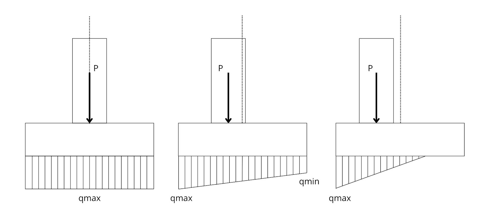
- Load Transfer and Stability: Ensuring the soil can support the applied loads without bearing failure.
- Stress Distribution: Accounting for the effects of eccentricity and applied moments on the soil-footing interface.
- Structural Strength: Verifying the footing’s resistance to bending, shear, and punching forces.
- Footing without Eccentricity vs. Geometric Eccentricity vs. Moment Eccentricity:
- The load is evenly distributed across the footing’s base, resulting in a uniform stress distribution on the soil below.
- Both the geometric and moment eccentricities are zero, ensuring the footing remains in full contact with the soil across its entire surface.
- The design process is simplified, as there are no additional moments or stress concentration zones to account for.
- Geometric eccentricity is introduced as an offset input in design calculations.
-
It adjusts the location of the load relative to the center of the footing, influencing moment and shear calculations.
-
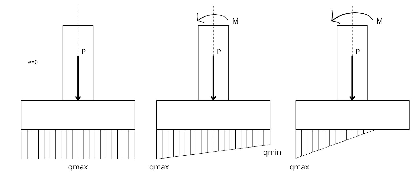
Moment eccentricity is accounted for using the formula:
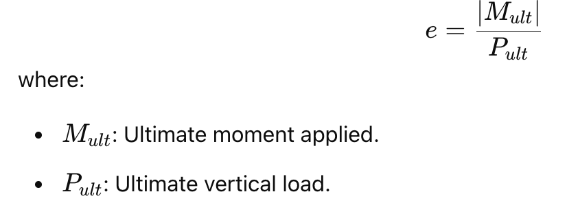
- This “effective eccentricity” is then used to adjust the stress distribution and calculate the effective bearing area of the footing.
2
Introduction to the Tool
The calculator simplifies the complex process of designing pad footings subjected to axial loads, moments, and eccentricity. By combining geotechnical and structural checks, it ensures stability and compliance for various loading scenarios, whether for centered or eccentric columns.
Common questions
What design standard does this calculator use?
What design standard does this calculator use?
The calculator applies AS 3600:2018 (incorporating Amendment 2) for reinforced concrete footing design. Limit state design (LRFD) is used throughout, factored loads are checked against design capacities for bending moment, one-way shear, and two-way (punching) shear at the critical perimeter.
What are the key inputs?
What are the key inputs?
Key inputs are footing plan dimensions (length, width), footing depth, column dimensions, concrete compressive strength (f’c), reinforcement bar size and spacing, cover to reinforcement, allowable bearing pressure, and applied loads (axial force, moment, and shear at the column base). Loads can be entered manually or linked from a column calculator above.
What checks and outputs does the calculator provide?
What checks and outputs does the calculator provide?
The calculator checks: bending moment in both plan directions with required flexural reinforcement, one-way shear (wide beam) in both directions, two-way punching shear at the critical perimeter around the column, and bearing pressure under service loads versus the allowable bearing capacity. Required reinforcement areas and utilization ratios are reported for each check.
How does load linking work for pad footings?
How does load linking work for pad footings?
Column axial force, moment, and shear at the base can be linked directly from a column calculator in the same Calcs.com project. When the column design changes, different section, loading, or height, the footing inputs update automatically, so footing adequacy is always checked against the current column reactions without manual re-entry.
Does this calculator handle eccentric or biaxial loading?
Does this calculator handle eccentric or biaxial loading?
The calculator handles uniaxial bending (axial load plus moment about one axis) with eccentricity checks to ensure the resultant load falls within the footing kern. For biaxial bending, the resultant eccentricity can be entered as equivalent uniaxial bending for preliminary sizing. Full biaxial analysis should be verified by the engineer for final design.
Can I link this footing directly to a column calculation?
Can I link this footing directly to a column calculation?
Yes. The axial force and moment at the column base link automatically from a connected column calculator. Change the column section or loads, and the footing recalculates immediately, bearing pressure, bending, shear, and punching shear all update without any manual transfer of reaction values.
Next steps
Design a Steel Screw Pile
Design steel screw piles to AS 2870:2011 and AS 2159:2009. Ultimate bearing and serviceability with geotechnical risk rating and corrosion allowance.
Design a Spread Footing (IBC 2024)
Design isolated spread footings to ACI 318-19 per IBC 2024 (ASCE 7-22): bearing, flexure, one-way and punching shear, and development length.
Calculate Concrete Development Length to AS 3600:2018
Calculate tension and compression development lengths for reinforcement to AS 3600:2018 (Amdt 2), with code references and modification factors.
Design a Concrete Beam to AS 3600:2018
Design rectangular concrete beams to AS 3600:2018 (Amdt 2) with unlimited spans. Checks flexure, shear, and short- and long-term deflection.
Changes in AS3600:2018 Amendment 2 (Concrete)
Changes in AS3600:2018 Amendment 2 (Concrete)
Design a Concrete Column to AS3600:2018
Design rectangular and circular reinforced concrete columns to AS 3600:2018 (Amdt 2), with P-M interaction, biaxial bending, slenderness and shear.