

AustraliaAS 2159:2009IBC 2024
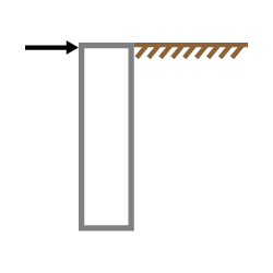
Analyze and design pile foundations under lateral loads to AS 2159:2009. Evaluates pile stability and strength, including deflection and bending demand along the embedded length.
Method & scope
What it calculates
Australian engineers designing piles that resist lateral loads, such as those beneath a retaining wall or carrying horizontal thrust from the structure above rather than pure axial load. The lateral force and moment at the pile head link from the connected wall or column calculation, so upstream changes update the design. Determine pile embedment depth and reinforcement from applied loads and soil conditions, so foundation sizing keeps pace with the structure above. Reactions link from connected beam, column, or retaining wall calculations.Calculation method
The calculator analyses a single reinforced concrete pile subjected to a lateral force and moment applied at its head. It sizes the embedment depth, checks soil and pile strength, verifies ground-level deflection, and designs the longitudinal and fitment reinforcement. The governing summary reports horizontal soil strength, moment demand and capacity, minimum embedment, and deflection, each as a demand-versus-capacity check.Horizontal soil strength
The lateral resistance of the surrounding soil is checked as horizontal soil strength demand against horizontal soil strength capacity, reported with a factor of safety. For cohesionless soils the allowable lateral bearing pressure at one third of the embedment depth governs the available resistance, following the IBC method. The geotechnical strength reduction factor from AS 2159:2009 is applied to the design ultimate geotechnical strength to give the design geotechnical strength.Pile strength: cohesive soils (Broms method)
For cohesive foundation soils the Broms method locates the point of zero shear down the pile, computes the maximum bending moment, and determines the length of pile resisting that moment. From the pile depth to diameter ratio and the load eccentricity to diameter ratio, a dimensionless horizontal resistance per unit is found, giving the minimum required pile depth for strength design. This is compared against the entered depth of embedment.Pile strength: cohesionless soils (IBC method)
For cohesionless soils the total factored horizontal force and moment, together with the equivalent height (effective eccentricity) of the loads, are used with the allowable lateral soil pressure at one third of the embedment depth to compute the ultimate pile capacity and the minimum required pile depth for strength design.Moment capacity and reinforcement design
The pile moment capacity is derived from a rectangular concrete compressive stress block over the circular section. The calculator resolves the neutral axis location, the chord length and central angle of the compressive stress block, the area and centroid of that block, and the total concrete compression force, then combines this with the longitudinal reinforcement to give the ultimate bending capacity. A bending capacity factor and a concrete placement factor reduce this to the factored pure bending moment. Bending reinforcement is designed for cohesive soils only. Longitudinal bars are arranged around the section from the entered bar number, type, and cover, and the fitment type sets a minimum fitment diameter and a maximum vertical spacing or helix pitch.Deflection (Broms method)
Serviceability is checked as the deflection at ground level against the maximum allowed deflection, with a pile deflection factor of safety. The calculator uses the concrete modulus of elasticity and the pile moment of inertia to form a dimensionless length of the pile system, then combines the load eccentricity to depth ratio with the coefficient of horizontal subgrade reaction to find the ground-level deflection, optionally including pile rotation.Assumptions
Earthquake loads and secondary effects such as liquefaction are not considered, the concrete pile is assumed not to crack, and combined axial loading with biaxial bending is not supported. A low-redundancy system is assumed, and pile fitments are not designed for shear forces. All utilization ratios must be 1.0 or less for the design to pass.How to use it
1
Open the calculator
Open it from Run calc in the About this calculator panel above.
2
Enter your inputs
Work through the input sections from top to bottom. Click any input label to see its reference explanation, clause, conditions and assumptions. See Checks, References, Conditions and Assumptions.
3
Review the results and export
Check the utilization of each governing check in the summary, then export a PDF report. See Views and Export.
Next steps
AU/NZ Calculator Library
Complete list of Calcs.com design calculators available for Australian and New Zealand projects (AS 3600, AS 4100, AS 1720, AS/NZS 1170, and related standards).
Design a Steel Screw Pile
Design steel screw piles to AS 2870:2011 and AS 2159:2009. Ultimate bearing and serviceability with geotechnical risk rating and corrosion allowance.
Bearing Capacity Calculator
Estimate soil bearing capacity below a shallow foundation using Meyerhof’s (1956) general bearing capacity equation, for preliminary sizing.
Design an L-Type Cantilever Retaining Wall to AS 4678:2002
Design L-type cantilever retaining walls to AS 4678:2002 and AS 3600:2018.
Use the Concrete Pad Footing Calculator AS 3600:2018
Design concrete pad footings to AS 3600:2018 (Amdt 2) with instant moment, shear and punching shear results.