

EuropeEN 1990:2002

The easy to use online Calcs.com Timber Beam Calculator for Eurocode enables you to do quick and powerful design and analysis for simple and continuous timber beams, with unlimited supports and loads. Easily create your own timber section dimensions and get instant results with our easy to understand traffic light checks for moment, deflection, and shear.
Background
The EU timber beam calculator can be used to calculate both the demands as well as the resistance of a straight beam.The analysis capabilities include:
- Point transverse forces and point uni-axial moments (excluding torsion)
- Line Loads (including linearly varying)
- Distributed Loads (including varying tributary width). For details on tributary widths, refer article 170-what-is-tributary-width
- ULS: Moment Resistance (EN 1995-1-1:2004 Cl 6.1.6)
- ULS: Shear Resistance (EN 1995-1-1:2004 Cl 6.1.7)
- ULS: Lateral Torsional Buckling (EN 1995-1-1:2004 Cl 6.3.3)
- ULS: Bearing at Supports (EN 1995-1-1:2004 Cl 6.1.5)
- SLS: Deflection analysis
- Softwood and Hardwood Timber
- Laminated Veneer Lumber (LVL)
- Glue Laminated Lumber
Tutorial
In this worked design example, we will go through the design process of a single-span LVL floor bearer. It will be holding 5 equally spaced beam floor joists and a residential live load. Joist spacing is at every 1500mm, and the beam is laterally restrained at every joist. It is for a residential ground floor hotel room in the United Kingdom (Category A3). This satisfies Service Class 1 for LVLs.
Method & scope
Informational and National Annexes
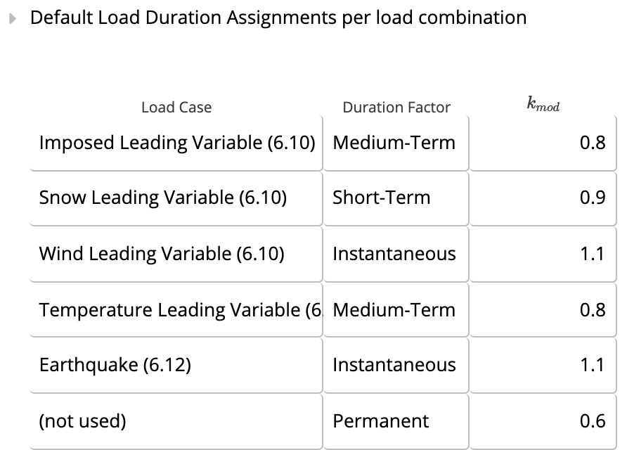
EN1995-1-1 identifies a number of clauses that may be specifically overridden by national annexes, which are summarized in the Foreword under Section “National Annex for EN 1995-1-1”. Calcs.com offers a handy section “Information and National Annexes” that gives access to review or alter these parameters quickly. Service Class - The service class dropdown affects the duration factors k_mod and the deformation factor k_def. We will set this to Service Class 2 in accordance with British National Annex Table NA.2 (Ground Floors). You will see a quick overview of the selected factors: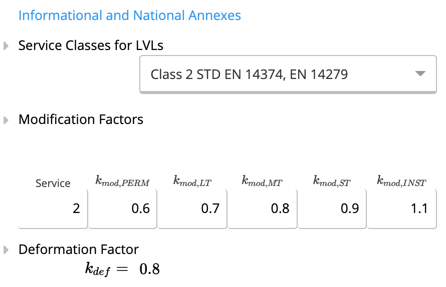
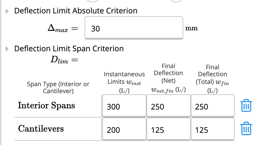
 Deflection limits: These pending upon the national annex and depending upon the use of the structure. In our case, we shall assume the structure is designed according to Table NA.5 BS EN1995-1-1:2004 (UK annex) and carries a plaster ceiling. Therefore, the final net load combination due to variable load only is span / 250. Instant limits may be chosen based on national requirements.
See the exact clause
Calculation method
Structural model and load combinations
The calculator models the timber beam as a one-dimensional element and computes bending moment, shear, and deflection diagrams under each EN 1990:2002 load combination. Loads are entered by type, permanent (G), variable (Q), wind (W), snow (S), and the calculator generates governing ultimate limit state (ULS) and serviceability limit state (SLS) combinations. Two deformation combinations are generated: instantaneous (characteristic combination) and final (accounting for creep via k_def).Material partial factor and k_mod
Characteristic strengths from the strength class (or custom input) are divided by the material partial factor gamma_M per EN 1995-1-1:2004 Cl 2.4.1 Table 2.3 (or the relevant National Annex). The resulting design strength is then multiplied by the modification factor k_mod, which accounts for service class (1, 2, or 3) and the governing load duration class (permanent through instantaneous) within each combination. design strength = f_k × k_mod / gamma_MBending strength (EN 1995-1-1:2004 Cl 6.1.6)
The design bending stress sigma_m,d is computed from the applied bending moment and the elastic section modulus W_y = b × d² / 6. The allowable bending strength f_m,d is derived from the characteristic bending strength adjusted by k_mod and gamma_M. For members with multiple plies, the group modification factor is applied. bending utilization = sigma_m,d / f_m,d ≤ 1.0Lateral torsional buckling (EN 1995-1-1:2004 Cl 6.3.3)
When the compression edge of the beam is not fully laterally restrained, the calculator checks lateral torsional buckling. The relative slenderness for bending lambda_rel,m is computed from the critical bending stress sigma_m,crit. Where lambda_rel,m exceeds 0.75, a stability factor k_crit is applied: reduced bending utilization = sigma_m,d / (k_crit × f_m,d) ≤ 1.0Shear strength
Design shear stress tau_d is computed from the maximum shear force and the cross-section area (b × d). It is checked against the design shear strength f_v,d = f_v,k × k_mod / gamma_M. shear utilization = tau_d / f_v,d ≤ 1.0Bearing strength (EN 1995-1-1:2004 Cl 6.1.5)
At each support, compressive stress perpendicular to grain sigma_c,90,d is checked against the design compressive strength perpendicular to grain f_c,90,d, modified by a factor k_c,90 that accounts for the support length and configuration. bearing utilization = sigma_c,90,d / (k_c,90 × f_c,90,d) ≤ 1.0Deformation checks (EN 1995-1-1:2004 Cl 2.2.3 and Table 7.2)
Instantaneous deformation u_inst is computed under the characteristic serviceability combination using the mean modulus of elasticity E_mean. Final deformation u_fin includes creep, computed using the effective modulus E_mean / (1 + k_def), where k_def is a creep factor that depends on service class and load duration. Both are checked against span-ratio limits from EN 1995-1-1:2004 Table 7.2 (or National Annex values), and against an optional user-defined absolute limit in mm.Load linking
Support reactions are exported as linked outputs. Connected column and footing calculations placed downstream in the same project receive updated reactions automatically whenever the beam inputs change.How to use it
1
Create a Calculation
When adding a new timber beam calculation, you can select between various types of residential timber beam. The sheet and calculations for each are the same, however, some default values and criteria, such as deflection limits and center to center spacing, have been made specific to each beam type. For this example, we will select a floor joist.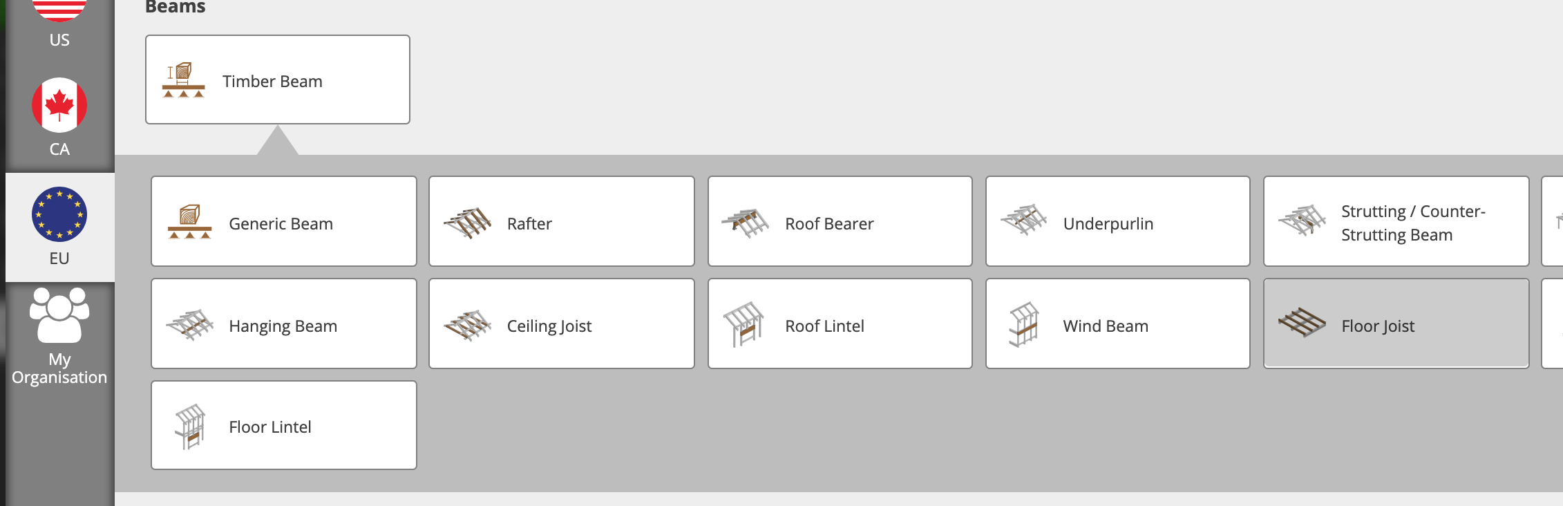
2
Entering our key properties
Quick Tip - If you’re ever unsure what something means in Calcs.com, simply click the field label for references, checks, conditionals, and descriptions.First, we enter the key properties of our beam:
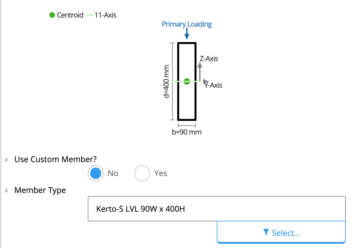
- Member Type - Clicking “Select” will open a list of all properties and allow you to select timber sizes from a database, or custom dimensioned timber. Refer to related article Quickly finding the best section with the member selector. We want to use a Kerto-S Laminated Veneer Lumber and initially select a member based on past experience:
- Total Beam Length - The length between start and end of the beam, irrespective of the support conditions. We select 6000 m.
- Length between lateral restraints - We are confident that the beam has adequate lateral bracing at each joist, so the length between lateral restraints is equal to our spacing of 1500 mm.
 Member Orientation - All timber beams can be analyzed bending about either Y or Z-axis. Where it is bending about the minor axis, some checks are not required (e.g. lateral torsional buckling). In our case we select “Loaded from Top”
-

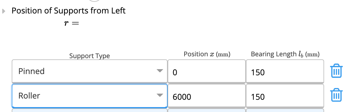
- Position of Supports from Left - The support conditions may be at any position along the beam. A cantilever can be created on either end by moving the support condition away from “0” or the “Total Beam Length”. In our case, the default simply supported position is adequate. The bearing length is used for bearing calculations l_contact to determine the effective bearing contact area and capacity.
3
Load Details
Calcs.com offers a number of ways to enter loads, to suit a range of uses. These include: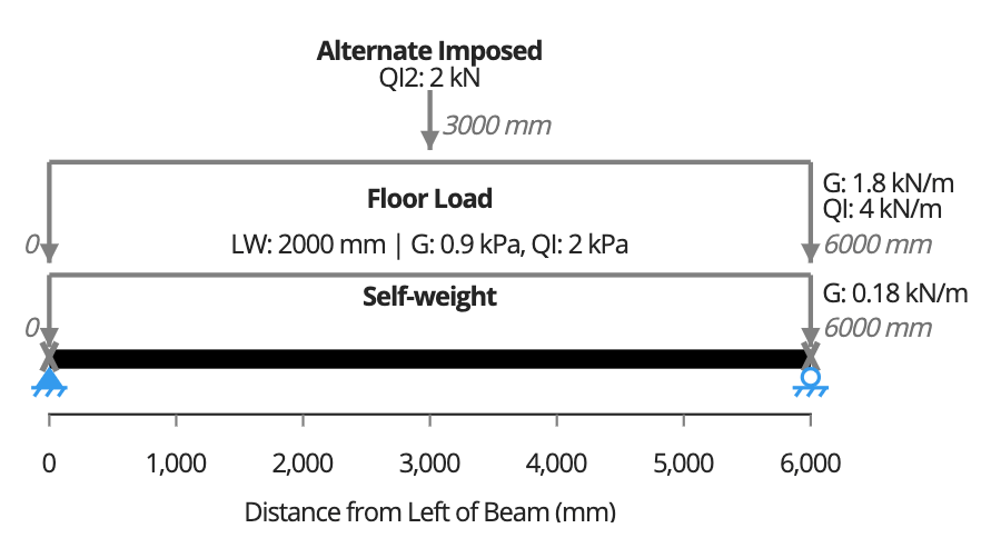
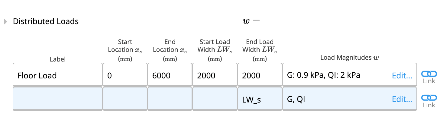

- Distributed Loads (kPa)
- Line Loads (kN/m)
- Point & Moment Loads (kN or kNm)
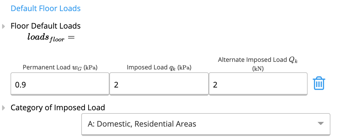
- Dead load - leave as 0.9 kPa to reflect the weight of the joists and flooring materials.
- Live Load - leave as 2 kPa to reflect the British National Annex Table NA.3,.
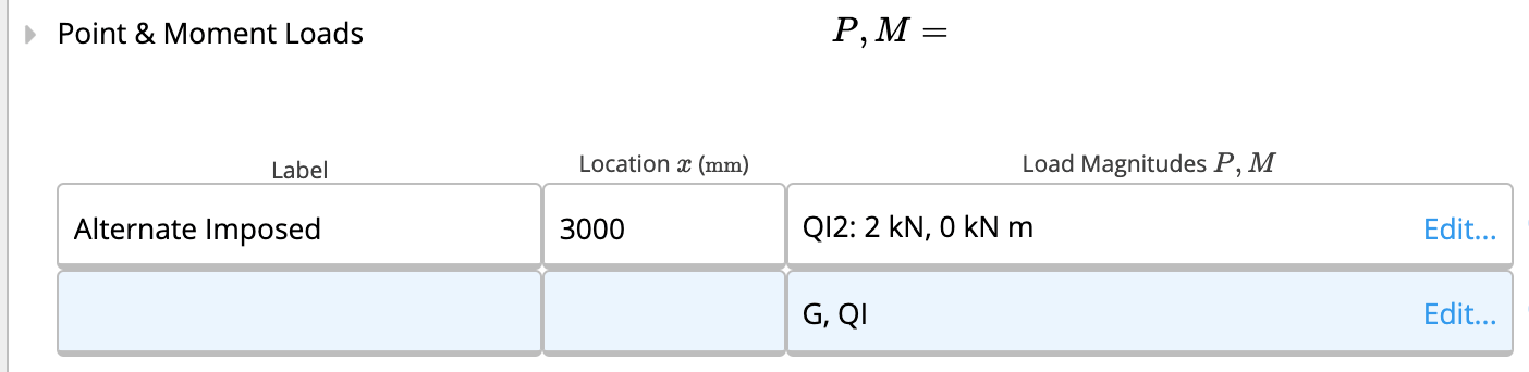
- Live Load - EN1991-1-1:2004 Cl 6.3.1.2 (3) requires that a concentrated load Qk acting alone should be taken into account. Using the British National Annex Table NA.3, we confirm Qk = 2 kN live load should be checked. Calcs.com “alternate” imposed loads QI, QI2 and QI3 are applied separately from each other, however are combined with other dead, snow, wind load types.In this case, it’s pretty clear that it won’t govern, but we will still apply for the example. Since the concentrated load doesn’t apply at the same time as the UDL, we’ll apply it in the “Point & Moment Loads” section.
4
Section selection
At this point, we can see that our beam passes, with the highest utilization of 90% for deflection. However, we want to make sure we’re getting the most out of our member, so go back to the member selector and review the various options available. We note we can achieve a fully utilized beam by reducing the thickness to a 81 thick LVL beam, instead of 90mm.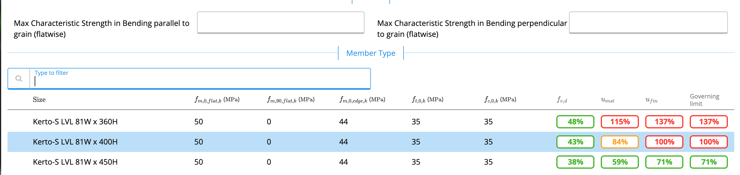
 We can also see the “factored” loads applied for each load combination. We can see that the QI2 = 2kN load was factored by 1.5x. Also the distributed load was converted to a line load and factored. QI and QI2 are not applied concurrently as discussed previously.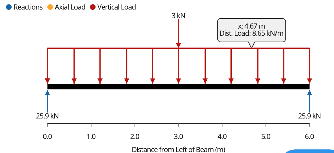
We can also see the “factored” loads applied for each load combination. We can see that the QI2 = 2kN load was factored by 1.5x. Also the distributed load was converted to a line load and factored. QI and QI2 are not applied concurrently as discussed previously.5
Printing and Member Schedule
Printing: We can now print our fully designed. Before finishing, let’s write a Comment to ourselves. This will appear in the printout.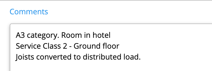
 And here is the printout ready for submission!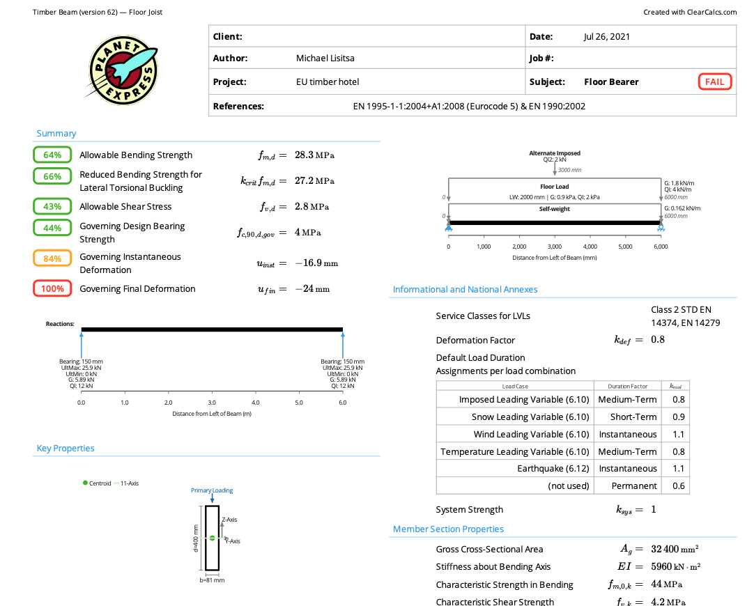
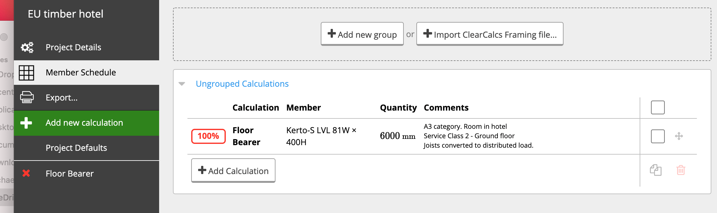
And here is the printout ready for submission!A more in-depth look
6
Detailed Mode
While the previous steps are all that is required to design our beam, it may be desirable to see more information about the beam. Calcs.com fully exposes all code calculations to see every step of the process employed to design the beam. For instance, we can go look at how the lateral-torsional buckling strength is calculated. Some calculations are hidden for clarity, however, they can be made visible by selecting “Detailed” mode. See 163-how-to-view-all-detailed-calculation-steps. For example, see the equation for the elastic critical buckling moment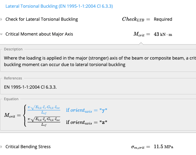
7
Multiple Laminations
Users may design custom sections, where the database doesn’t have the exact size and grade you need. In addition, a database or custom section can be laminated, with all laminations working in composite.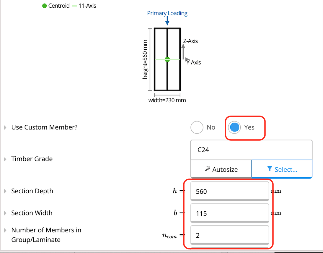
Available presets
Each preset opens the calculator with a typical setup already entered.Common questions
What design standard does this calculator use?
What design standard does this calculator use?
The calculator designs timber beams to EN 1995-1-1:2004+A1:2008 (Eurocode 5), with load combinations per EN 1990:2002. Partial factors for material properties follow EN 1995-1-1:2004 Cl 2.4.1 Table 2.3 or the relevant National Annex value, which can be overridden in the calculator inputs.
How do I define a timber section?
How do I define a timber section?
This calculator uses custom cross-section dimensions, you enter the section depth and width directly rather than selecting from a database. This suits design scenarios where a specific section size or non-standard product is being checked. Enter your dimensions and the calculator derives all required section properties (A, I, W_y, W_z) automatically.
What checks and outputs does it produce?
What checks and outputs does it produce?
The calculator checks bending strength (EN 1995-1-1:2004 Cl 6.1.6), lateral torsional buckling (Cl 6.3.3), shear stress, bearing strength at supports (Cl 6.1.5), governing instantaneous deformation (Cl 2.2.3(2)), and governing final deformation including creep (Cl 2.2.3(5)). Deformation limits reference EN 1995-1-1:2004 Table 7.2 or a user-defined absolute limit.
How is lateral torsional buckling checked?
How is lateral torsional buckling checked?
The calculator determines the critical bending stress for lateral torsional buckling per EN 1995-1-1:2004 Cl 6.3.3. Where the relative slenderness for bending lambda_rel,m exceeds the threshold, a stability factor k_crit less than 1.0 is applied to reduce the allowable bending strength. The calculator shows the governing lambda_rel,m and k_crit alongside the bending utilization ratio.
What modification factors are applied to timber strengths?
What modification factors are applied to timber strengths?
Characteristic strengths are reduced by the partial factor gamma_M and modified by k_mod, which depends on service class and load duration class. Service class (1, 2, or 3) and load duration class (permanent, long-term, medium-term, short-term, or instantaneous) are user inputs. For laminated members, the group modification factor is applied per EN 1995-1-1:2004.
Does this calculator support load linking with column and footing calculations?
Does this calculator support load linking with column and footing calculations?
Yes, beam reactions link directly to connected column and footing calculations in the same project. When you update a span, load, or section dimension, all downstream calculations update automatically, no manual re-entry of reactions required.
Next steps
Design a Wood Column to EN1995
Design timber columns and studs to EN 1995-1-1:2004 (Eurocode 5), with load linking and a database of European and UK timber sections.