

EuropeEN 1990:2002

The Calcs.com custom section timber column calculator to EN 1995-1-1:2004 enables the fast and accurate design of timber columns and studs to Eurocode standards. With support for dynamic load linking between beams and columns, easily design accurate and quality engineered columns, and create your own timber dimensions from our database of thousands of European and UK timber sections.
Background
The EU timber columns calculator can be used to calculate both the demands as well as the resistance of a straight column.The analysis capabilities include:
- Point Axial and Lateral forces
- Point Moments in the major and minor axis (excluding torsion)
- Line Loads (including linearly varying)
- Distributed Loads (including varying tributary width). For details on tributary widths, refer article 170-what-is-tributary-width
- ULS: Section Bending Moment Capacity (EN 1995-1-1:2004 Cl 6.1.6)
- ULS: Shear Resistance (EN 1995-1-1:2004 Cl 6.1.7)
- ULS: Section Compression And Bending (EN 1995-1-1:2004 Cl 6.2.3 & 6.2.4)
- ULS: Compression / Combined with Bending: Flexural Buckling (EN1995-1-1:2004 Cl 6.3.2)
- ULS: Bending or combined bending & compression: Lateral Torsional stability (EN 1995-1-1:2004 Cl 6.3.3)
- SLS: Deflection analysis
- Softwood and Hardwood Timber
- Laminated Veneer Lumber (LVL)
- Glue Laminated Lumber
Tutorial
In this worked design example, we will go through the design process of a single-story stud wall. It is pinned at the top and bottom (restrained in translation, but not in rotation about the z-z or y-y axis). It is for a residential building and is exposed to Service Class 2. A central batten provides restraint for bending about the Z-axis, but not in the Y-axis (refer snapshot below).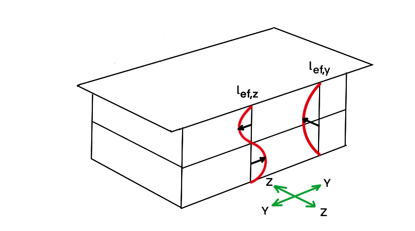
Method & scope
See the exact clause
Calculation method
Structural model and load combinations
The calculator models the timber column as a member under combined axial compression and biaxial bending. Loads are entered by type, permanent (G), variable (Q), wind (W), and EN 1990:2002 governing ULS combinations are generated automatically. Bending moments can be entered directly or received via load linking from beam calculations above. Deformation checks use serviceability combinations.Material partial factor and k_mod
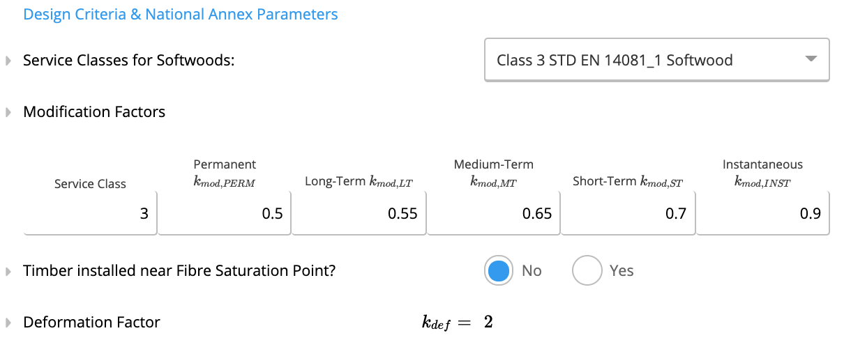
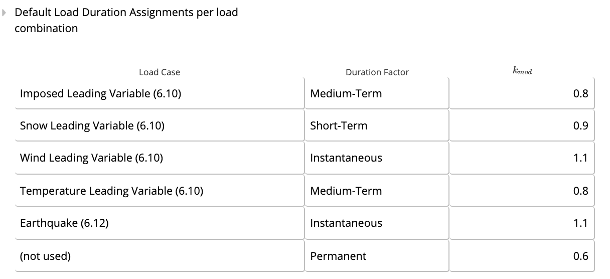
Characteristic strengths are divided by the material partial factor gamma_M and modified by k_mod based on service class (1, 2, or 3) and load duration class. The combination that produces the worst utilization governs. design strength = f_k × k_mod / gamma_MCross-section compression (EN 1995-1-1:2004 Cl 6.1.4)
Design compressive stress sigma_c,0,d = N_d / A is checked against the design compressive strength f_c,0,d. compression utilization = sigma_c,0,d / f_c,0,d ≤ 1.0Bending strength about each axis (EN 1995-1-1:2004 Cl 6.1.6)
Bending stresses about the Y-axis and Z-axis are each checked against their respective design bending strengths. For rectangular sections, the same characteristic bending strength applies to both axes, adjusted by k_mod and gamma_M.Shear strength about each axis (EN 1995-1-1:2004 Cl 6.1.7)
Shear stresses induced by forces in each plane are checked against the design shear strength f_v,d. The effective shear area accounts for the cross-section geometry.Cross-section bending and compression interaction (EN 1995-1-1:2004 Eq 6.19 and 6.20)
When axial compression and biaxial bending are combined, the cross-section interaction is checked through two simultaneous equations (Eq 6.19 and 6.20) that weight the demands by the km factor: interaction = sigma_c,0,d/f_c,0,d + sigma_m,y,d/f_m,y,d + km × sigma_m,z,d/f_m,z,d ≤ 1.0 interaction = sigma_c,0,d/f_c,0,d + km × sigma_m,y,d/f_m,y,d + sigma_m,z,d/f_m,z,d ≤ 1.0Flexural buckling interaction (EN 1995-1-1:2004 Cl 6.3.2, Eq 6.23 and 6.24)
Compressive resistance is reduced by the buckling factor k_c,y (about Y-axis) and k_c,z (about Z-axis), each derived from the relative slenderness lambda_rel,c for that axis. The combined flexural-buckling and bending interaction is checked as: interaction = sigma_c,0,d / (k_c,y × f_c,0,d) + sigma_m,y,d/f_m,y,d + km × sigma_m,z,d/f_m,z,d ≤ 1.0 interaction = sigma_c,0,d / (k_c,z × f_c,0,d) + km × sigma_m,y,d/f_m,y,d + sigma_m,z,d/f_m,z,d ≤ 1.0Lateral torsional buckling interaction (EN 1995-1-1:2004 Cl 6.3.3, Eq 6.35)
When the compression face of the column is unrestrained against lateral movement, lateral torsional buckling is checked. The stability factor k_crit is applied to the major-axis bending strength, and the interaction with axial compression is checked per Eq 6.35: interaction = (sigma_m,y,d / (k_crit × f_m,y,d))² + sigma_c,0,d / (k_c,z × f_c,0,d) ≤ 1.0Deformation checks (EN 1995-1-1:2004 Cl 2.2.3)
Governing instantaneous and final (creep-adjusted) deformations are computed for bending about each axis independently. All four combinations (instantaneous Y, instantaneous Z, final Y, final Z) are checked against span-ratio limits from EN 1995-1-1:2004 Table 7.2 and any user-defined absolute limits.Load linking
The column’s base reaction is exported as a linked output to connected footing calculations. Axial load at the column top can be linked from beam reactions above, completing the full load path from beam to column to footing automatically.How to use it
1
Create a Calculation
When adding a new timber column calculation, you can select between various types of residential walls. The sheet and calculations for each are the same, however, some default values and criteria, such as deflection limits and center to center spacing, have been made specific to each column type.For this example, we will select an exterior stud wall.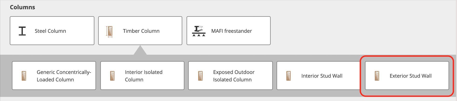
2
Entering our key properties
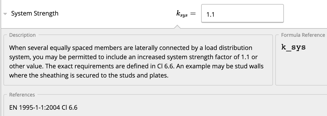
Quick Tip - If you’re ever unsure what something means in Calcs.com, simply click the field label for references, checks, conditionals, and descriptions. For example:
 First, we enter the key properties of our column: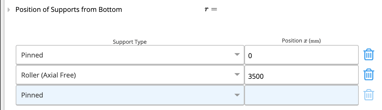
First, we enter the key properties of our column:- Member Type - Clicking “Select” will open a list of all properties and allow you to select timber sizes from a database, or custom dimensioned timber. Refer to related article Quickly finding the best section with the member selector. We want to use custom dimensions Softwood Timber of grade C20, and select a dimension based on past experience:
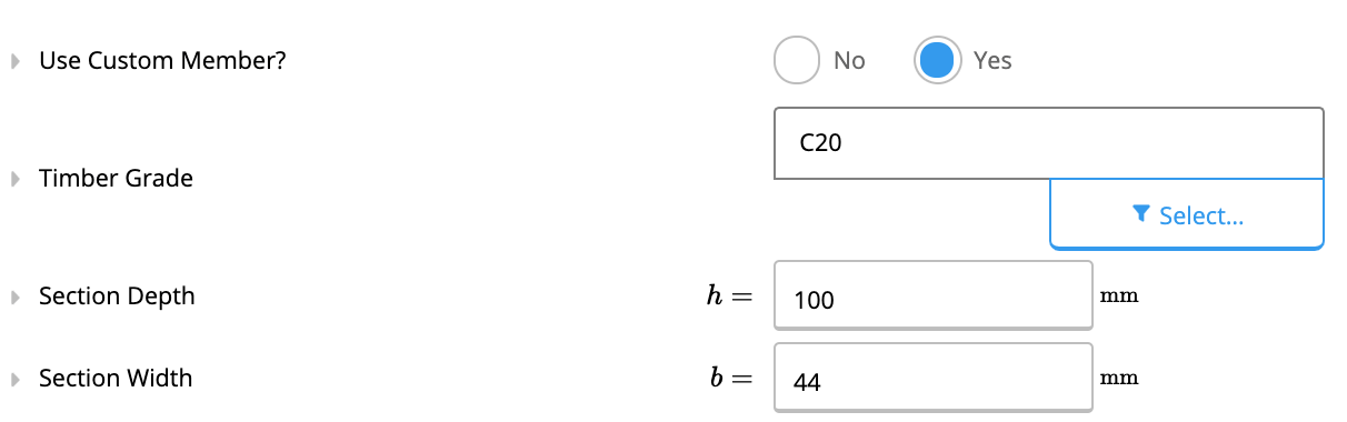
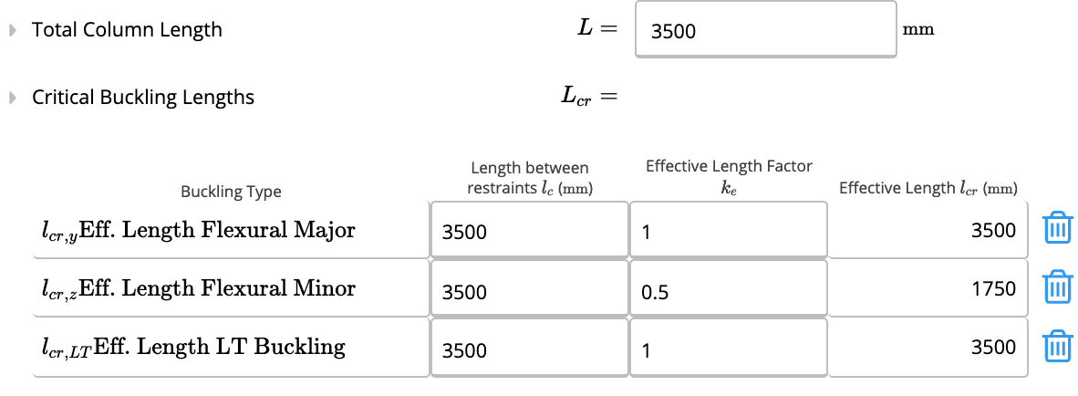
- Total Column Length - Select the length between the start and end of the column. We select 3500 mm.
- Critical Buckling Lengths - We are confident that the column has adequate lateral bracing at the batten (braced about z-z axis as per diagram above), so the length between lateral restraints is equal to half the column length (1750 mm).
-
- Position of Supports from Bottom - The support conditions may be at any position along the column, and can include 1 or more supports. A cantilever can be created on either end by moving the support condition away from “0” or the “Total Span Length”. In our case, the default simply supported position is adequate.
3
Load Details
Calcs.com offers a number of ways to enter loads, to suit a range of uses. These include: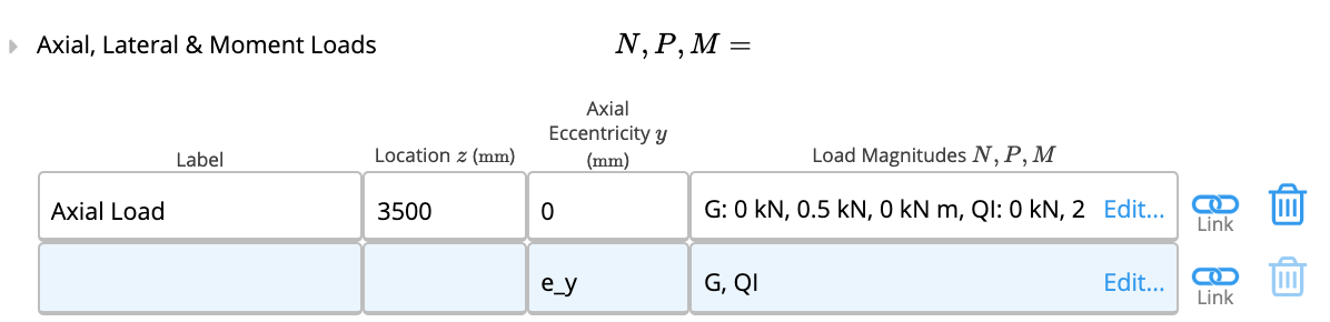

 Deflection limits: These depend on the national annex and the use of the structure. In the UK annex Table NA.5 BS EN1995-1-1:2004+A1:2008 only beam deflection limits are given. In our case, we know that the wind load will not cause significant lateral bending and we can ignore the calculation. We may set arbitrarily high deflection limits to ensure the check will not exceed any deflection requirements: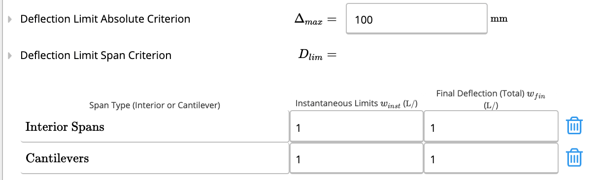
- Distributed Loads (kPa)
- Line Loads (kN/m)
- Point & Moment Loads (kN or kNm)
- Enter the start and end location. Note you can type the ID of any variable, or even include a formula in each input cell. In our case “L” is sufficient.
-
Enter the start and end load width. Refer 170-what-is-tributary-width for further details.

Deflection limits: These depend on the national annex and the use of the structure. In the UK annex Table NA.5 BS EN1995-1-1:2004+A1:2008 only beam deflection limits are given. In our case, we know that the wind load will not cause significant lateral bending and we can ignore the calculation. We may set arbitrarily high deflection limits to ensure the check will not exceed any deflection requirements:- Section selection
4
Summary of results and internal force diagrams
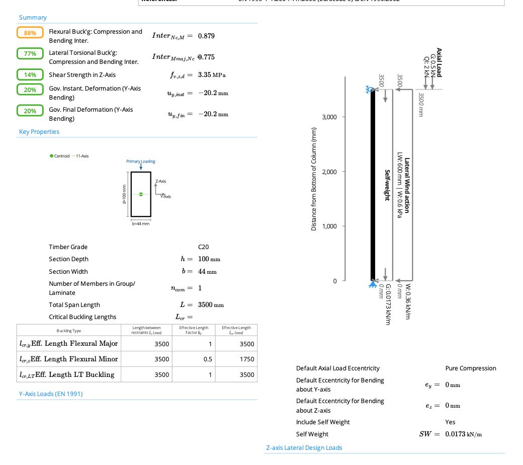
Once we’ve got our column design, we can quickly glance at relevant values to make sure everything corresponds to what we’d expect. On the right panel is the summary section, where we find things such as the critical moment demand and capacity, shear, moment and deflections. Where a calculation for lateral-torsional buckling was required based on Eurocode criteria, totals will also be shown. Where buckling does not govern (stocky column), the cross-section interaction checks will be shown instead.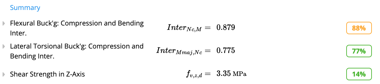
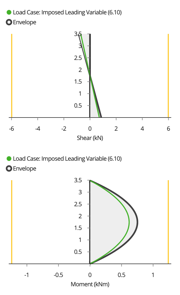
We can also see the “factored” loads applied for each load combination. We can see that the G = 0.5 kN and QI = 2 kN loads were factored by 1.35 x and 1.5x respectively giving us 3.68 kN total factored axial load. Also, the distributed loads and self-weight were converted to a line load and factored.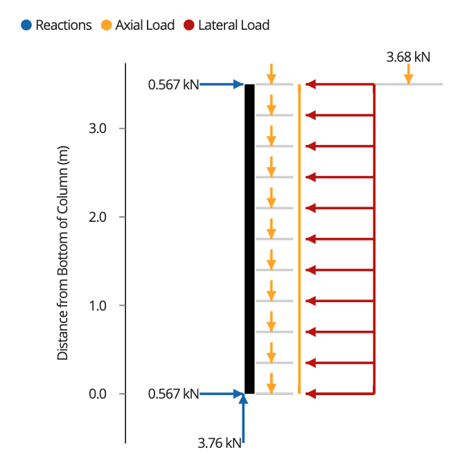
We can also see the “factored” loads applied for each load combination. We can see that the G = 0.5 kN and QI = 2 kN loads were factored by 1.35 x and 1.5x respectively giving us 3.68 kN total factored axial load. Also, the distributed loads and self-weight were converted to a line load and factored.
5
Printing and Member Schedule
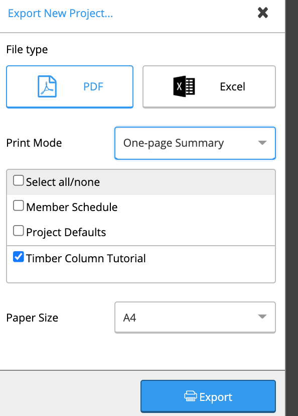
Printing: We can now print our fully designed. Before finishing, let’s write a Comment to ourselves. This will appear in the printout.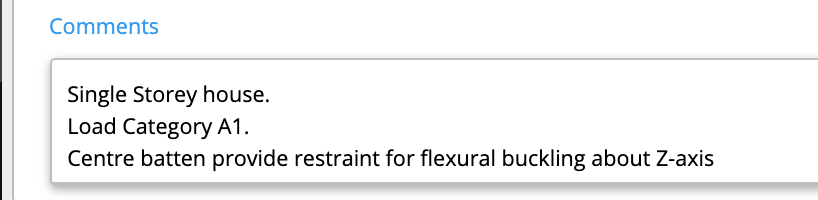

A more in-depth look
6
Detailed Mode
While the previous steps are all that is required to design our column, it may be desirable to see the steps in more detail. Calcs.com fully exposes all code calculations to see every step of the process employed in any of our calculators. For instance, we can go look at how flexural buckling checks are calculated. Some calculations are hidden for clarity, however, they can be made visible by selecting “Detailed” mode. See 163-how-to-view-all-detailed-calculation-steps. For example, see some key inputs for flexural buckling found by scrolling down in the left column, and clicking on the heading to expand.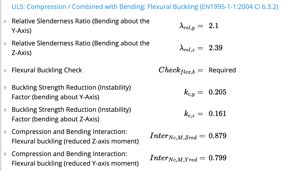
7
Multiple Laminations
Users may design custom sections, where the database doesn’t have the exact size and grade you need. In addition, any timber section can be stacked horizontally (laminated), to act as one composite member.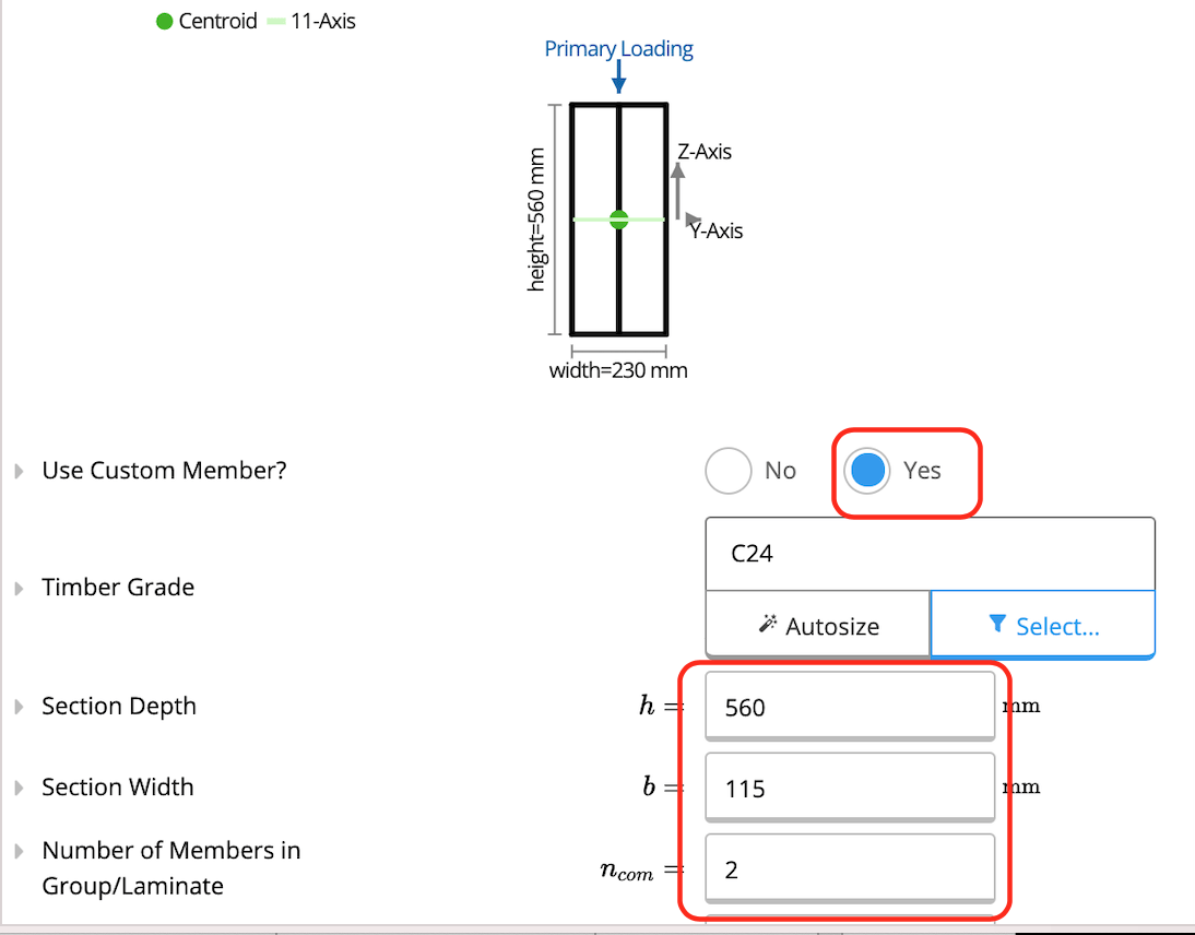

Axial Load Eccentricity
Do you sometimes need to check for the axial load being positioned eccentrically to your column, and thereby inducing some bending moment? This is easy to do by selecting from various predefined options in “Default Axial Load Eccentricity”, or even assigning eccentricities per load case.Available presets
Each preset opens the calculator with a typical setup already entered.Common questions
What design standard does this calculator use?
What design standard does this calculator use?
The calculator designs timber columns to EN 1995-1-1:2004+A1:2008 (Eurocode 5), with load combinations per EN 1990:2002. Material partial factors follow EN 1995-1-1:2004 Cl 2.4.1 Table 2.3 or the relevant National Annex. The calculator checks both the cross-section resistance and the member resistance including buckling.
How do I define a timber section?
How do I define a timber section?
Section depth and width are entered as direct inputs, this is a custom-section calculator. You can also select from a database of European and UK timber sections to populate the dimensions. The calculator derives all cross-section properties (A, I_y, I_z, W_y, W_z) from the dimensions automatically.
What checks and outputs does it produce?
What checks and outputs does it produce?
The calculator checks cross-section axial compression (EN 1995-1-1:2004 Cl 6.1.4), bending about both axes (Cl 6.1.6), shear about both axes (Cl 6.1.7), cross-section bending-and-compression interaction (Eq 6.19 and 6.20), flexural buckling combined with bending (Cl 6.3.2, Eq 6.23 and 6.24), lateral torsional buckling combined with compression (Cl 6.3.3, Eq 6.35), and governing instantaneous and final deformation about both axes.
How are the combined interaction checks structured?
How are the combined interaction checks structured?
Three separate interaction checks are performed. First, the cross-section interaction (Eq 6.19 and 6.20) checks the combined demands at the most-stressed cross-section without buckling. Second, flexural buckling interaction (Cl 6.3.2) reduces compressive resistance by a factor k_c based on the slenderness ratio about each axis. Third, lateral torsional buckling interaction (Cl 6.3.3, Eq 6.35) applies when the compression edge of the column is unrestrained against lateral movement.
How are flexural buckling lengths handled for each axis?
How are flexural buckling lengths handled for each axis?
Effective lengths for buckling about the major and minor axes are specified independently, allowing different bracing conditions in each plane, common for wall studs with blocking in one direction only or columns in moment frames. The buckling reduction factor k_c is computed from the relative slenderness lambda_rel,c for each axis, which combines the effective length, cross-section radius of gyration, and the critical Euler load.
Does this calculator support load linking with beam and footing calculations?
Does this calculator support load linking with beam and footing calculations?
Yes, axial load at the column top can be linked from beam reactions above, and the column’s base reaction links to connected footing calculations. The full load path, beam to column to footing, updates automatically whenever any upstream input changes.
Next steps
Design a Wood Beam to EN1995
Design simple and continuous timber beams to EN 1995-1-1:2004+A1:2008 (Eurocode 5) with unlimited supports and loads.