

United StatesAISC 360-22 (ASD)

Beam reactions link to the columns and footings below, so load changes propagate downstream automatically. Design closed-section steel beams subject to torsion to AISC 360-22 ASD. Combined bending, shear, and torsion are checked per Chapter H alongside standard deflection limits.
Follow along in this video or the below article to see an overview of the key assumptions, inputs and outputs for steel HSS with torsion:
The calculator shares most assumptions with the standard Steel Beam calculator, with a few torsion-specific notes:
- Warping torsion is not considered; only closed-section torsional checks are performed.
- Members are assumed to be straight and prismatic (no tapering).
- Axial loads due to twist are assumed negligible.
- This is a particularly important point for inclined beams, in which axial load is by definition non-zero; it is left to the engineer to verify that the axial load is, in fact, negligible.
1
Inputting Key Properties
At the top of the calculator, you’ll choose your steel section: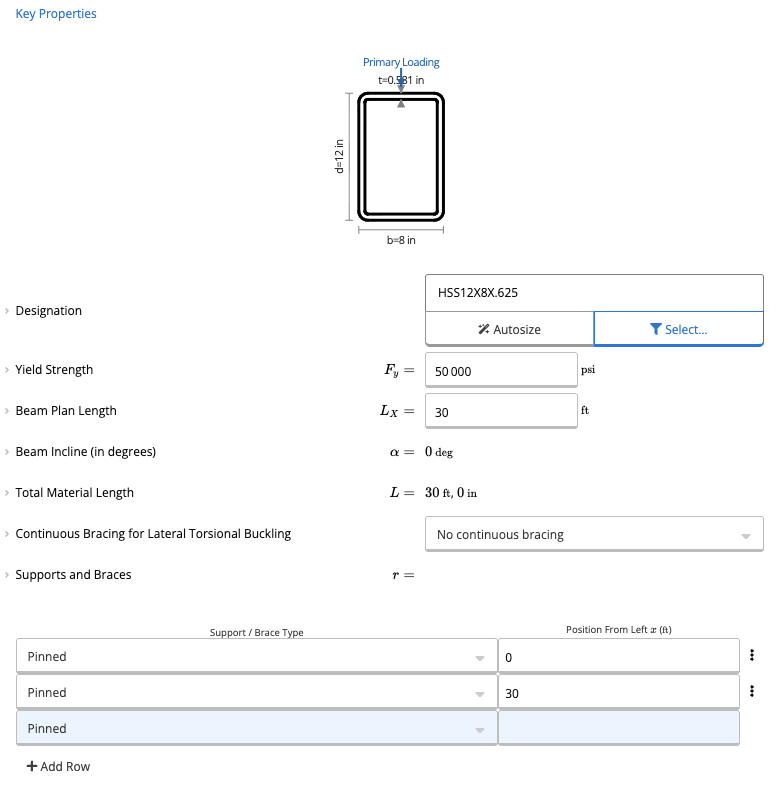
- Open the Member Selector.
- Select the desired HSS section (closed sections only are currently supported for torsion).
- Adjust material and member properties as needed:
- Yield strength (Fy)
- Beam span length
- Bracing conditions
2
Applying Torsional Load Input
The first load shown is the Required Torsional Load (T_req):
- This value represents the factored torsional moment applied to the beam.
- This load represents the twist-inducing moment acting on the member.
3
Applying Additional Loads
Similar to the regular Steel Beam calculator, you may add:
- Distributed loads
- Line loads
- Point loads
Method & scope
What it calculates
Beam reactions link to your column and footing calculations automatically, change a load once and everything downstream updates. For US structural engineers designing closed-section steel beams subject to torsional loading under AISC 360-22 ASD. Checks combined bending, shear, and torsion per Chapter H alongside standard deflection limits. Check steel beams for torsion when shear loads are offset from the shear center, combined with bending and shear in one template.Calculation method
The Steel Beam With Torsion (ASD, AISC 360-22) calculator performs a full ASD strength and serviceability check per the current AISC Specification, extending the standard beam checks with closed-section torsion provisions from Chapter H.Section classification (AISC 360-22 B4)
Wall slenderness for closed HSS sections is checked against lambda_p and lambda_r limits per B4. The maximum slenderness ratio is also evaluated and reported. Classification governs both the FLB capacity reduction and the section’s torsional shear properties.Flexural capacity, AISC 360-22 Chapter F
Allowable bending moment is Mn / Omega_b with Omega_b = 1.67. For compact closed sections yielding typically governs; for noncompact or slender sections FLB reductions reduce the available strength. LTB is evaluated per Chapter F using Lb, Lp, Lr, and the Cb factor. utilization = M_service / (Mn / 1.67) ≤ 1.0 for positive and negative bending separately.Shear capacity, AISC 360-22 Chapter G
utilization = V_service / (0.6 Fy Aw Cv1 / 1.67) ≤ 1.0. The web shear coefficient Cv1 is based on the section’s h/tw ratio per Chapter G provisions.Closed section torsion checks, AISC 360-22 Chapter H
Torsional shear stress is calculated from the applied torque using the St. Venant closed-section formula. The combined limit state of torsion, shear, and flexure is evaluated per Chapter H: utilization = (Combined torsion, shear, and flexure demand) / (Allowable combined strength) ≤ 1.0 The allowable torsion strength is controlled by the onset of yielding under the combined shear stress field from flexure and torsion acting simultaneously. Both the torsion strength check and the combined interaction are reported in the summary.Load combination analysis
Service-level ASD combinations are evaluated with FEA (D; D+L; D+S; D+0.6W; etc.). The governing combination for moment and for shear is identified. Torsional loads are combined with gravity demands across all applicable combinations.Deflection checks
Three deflection limits are tracked: instantaneous deflection, long-term deflection (including creep), and simplified DL+(LL or SL) deflection. utilization = delta / delta_allow ≤ 1.0 for each.Inputs summary
Section (closed HSS), yield strength Fy, span lengths, support types, incline pitch, applied bending loads and tributary widths, required torsional loads, and three sets of deflection limit criteria.Outputs summary
Summary: allowable bending moment and demand, allowable and actual shear, torsional load and allowable torsion, combined torsion-shear-flexure interaction ratio, maximum slenderness ratio, maximum vertical and horizontal reactions, and three deflection ratios. Reactions are structured for direct load linking to downstream column and footing calculations.How to use it
1
Reviewing the Calculations
This calculator will compute the flexural capacity based on AISC 36-16 Chapter F. Similar to the steel beam calculator, governing lateral torsional buckling checks are completed.Calcs.com checks for the moment modification factor using the quarter-moment method, which is later used to determine the LTB moment resistance. This calculator also does a simple shear capacity check.For the closed section torsion checks, you can scroll to the bottom of the calculator and open the below dropdown.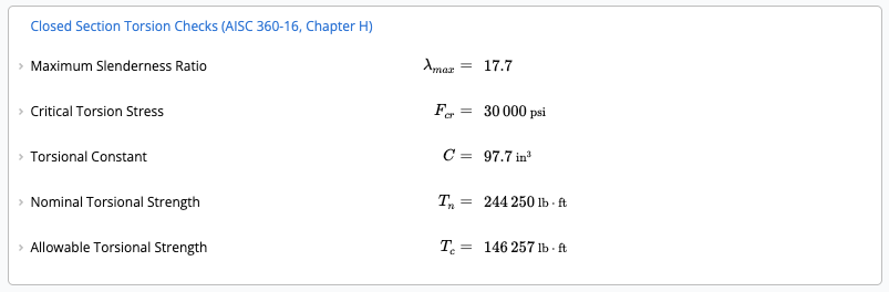
2
Combined Loading Check
If your torsional demand exceeds 20% of the allowable torsional strength, the calculator automatically performs a combined torsion + shear + axial interaction check.For example, if the torsional demand is increased to reflect higher loading:
- The calculator evaluates the interaction equation defined by AISC.
- A combined utilization result (e.g., 0.54 < 1.0) will appear, confirming compliance.
Available presets
Each preset opens the calculator with a typical setup already entered.Common questions
What design method and code standard does this calculator use?
What design method and code standard does this calculator use?
This calculator uses Allowable Strength Design (ASD) per AISC 360-22, the current edition of the AISC Specification. Combined torsion, shear, and flexure are checked per Chapter H with allowable strengths of Rn / Omega.
What are the key inputs?
What are the key inputs?
Key inputs include section designation (closed HSS rectangular or square), yield strength Fy, span lengths and support conditions, service-level bending loads with tributary widths, required torsional loads, unbraced length, and deflection limit criteria for live load, long-term, and DL+(LL or SL) checks.
What does it check or output?
What does it check or output?
The calculator checks allowable bending moment (AISC 360-22 Chapter F), allowable shear (Chapter G), torsional strength and combined torsion-shear-flexure interaction (Chapter H), maximum slenderness ratio, and three deflection limits. The summary shows torsional load demand, allowable torsion, combined interaction ratio, and support reactions.
What section types support torsion checks in this calculator?
What section types support torsion checks in this calculator?
The torsion module applies to closed HSS sections (rectangular and square tubes) where St. Venant torsion governs. The closed-section torsion formula is used to compute shear stress from torque. Open sections such as W-shapes are not covered by this calculator’s torsion provisions.
When should I use this versus steelBeamTorsionASD (AISC 360-16)?
When should I use this versus steelBeamTorsionASD (AISC 360-16)?
Use this calculator for projects referencing AISC 360-22 or when the authority having jurisdiction requires the current edition. Use steelBeamTorsionASD when the project references AISC 360-16. Both calculators apply ASD with closed-section torsion; the 2022 edition includes minor updates to section classification and LTB provisions.
Does this calculator support load linking with column and footing calculations?
Does this calculator support load linking with column and footing calculations?
Yes, beam reactions at supports link directly to connected column and footing calculations in the same project. When span length, loads, or member size changes, all connected calculations update automatically, no manual re-entry.
Next steps
Design a Steel Beam (ASD) to AISC 360-22
Design hot-rolled steel beams to AISC 360-22 (ASD) with multiple spans and service-level loads. Checks bending, shear and three deflection limits.
Design a Steel Beam (LRFD) to AISC 360-22
Design and analyze steel beams to AISC 360-22 (LRFD) with multiple supports and loads. Presets for floor and roof beams cut repetitive data entry.