Beam reactions link to the columns and footings below, so load changes propagate downstream automatically. Design hot-rolled steel beams to AISC 360-22 ASD with multiple spans and service-level loads. Checks allowable bending (Chapter F), allowable shear (Chapter G), and three deflection limits.
The Calcs.com Steel Beam Calculator allows users to design steel beams by specifying the desired load cases and dimensions of the beam. In this article, each section of the calculator will be explained plus followed by a few worked examples. If you’d prefer to watch a video overview, check out the video below.The Steel Beam Calculator has 4 main sections
Every check in this calculator links back to its governing clause in AISC 360-16. Open the Formula Reference panel on any result and select the clause reference to read it. See Viewing Clauses from Inside a Calculator.
The Steel Beam (ASD, AISC 360-22) calculator performs a full allowable strength and serviceability check per AISC 360-22 on hot-rolled steel beams with any number of spans and loads.
Section classification (AISC 360-22 B4)
Flanges and webs are classified as compact, noncompact, or slender by comparing width-to-thickness ratios to lambda_p and lambda_r limits. Classification governs whether full plastic moment capacity is available or whether flange and web local buckling reductions apply.
Flexural capacity, AISC 360-22 Chapter F
Allowable bending strength is Mn / Omega_b where Omega_b = 1.67. Positive and negative bending are evaluated separately. For compact sections: utilization = M_service / (Mn / 1.67) ≤ 1.0. Lateral-torsional buckling is checked with the unbraced length Lb against limiting lengths Lp and Lr. The Cb moment gradient factor is applied to account for moment variation along the unbraced length. Flange local buckling and web local buckling reductions are applied for noncompact and slender elements.
Shear capacity, AISC 360-22 Chapter G
Allowable shear strength is Vn / Omega_v where Omega_v = 1.67. For standard W-shapes: utilization = V_service / (0.6 Fy Aw Cv1 / 1.67) ≤ 1.0. The web shear coefficient Cv1 or Cv2 is selected based on web slenderness h/tw.
Load combination analysis
All applicable ASD service-level combinations are run with FEA (D; D+L; D+S; D+0.75L+0.75S; D+0.6W; etc.). The governing combination for moment and for shear is identified separately. Unfactored load cases are used directly for ASD demand calculations and for deflection computations.
Deflection checks
Three serviceability deflection limits are tracked:
Instantaneous deflection, compared to L/n or absolute value (typically L/360 for floor beam live load)
Long-term deflection, includes creep amplification of sustained loads; typically L/240
Simplified DL+(LL or SL) deflection, combined dead plus live or snow
utilization = delta / delta_allow ≤ 1.0 for each criterion.
Inputs summary
Geometry: section designation, yield strength Fy (ksi), span lengths, support types, incline pitch, tributary spacing. Loads: service-level dead, live, roof live, snow, and wind loads applied as uniform, partial, point, or moment loads. Design criteria: separate deflection limit inputs for live load, long-term, and simplified combined deflection.
Outputs summary
The summary reports critical moment demand and allowable moment, governing load combination for moment and shear, shear demand and allowable shear, maximum vertical and horizontal reactions, and deflection ratios for all three criteria. Reactions are structured for direct load linking to column and footing calculations downstream.
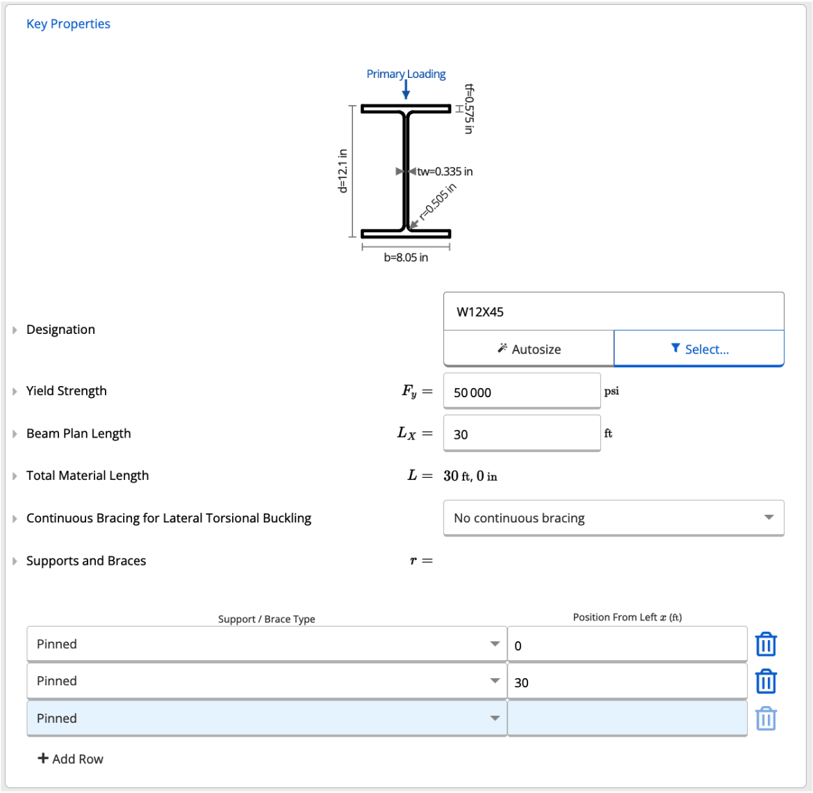
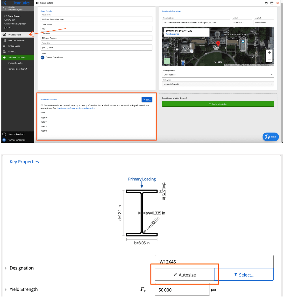
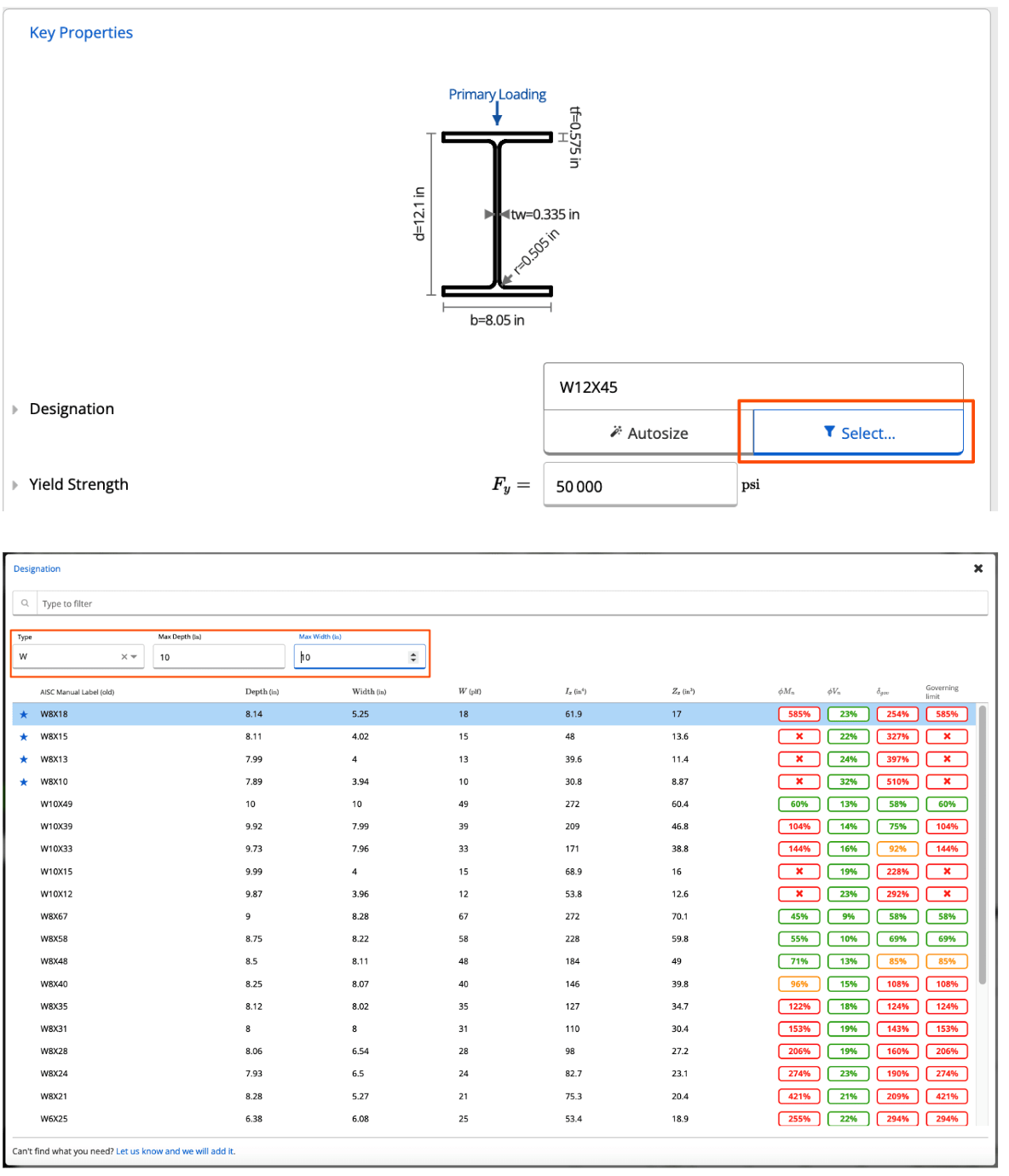
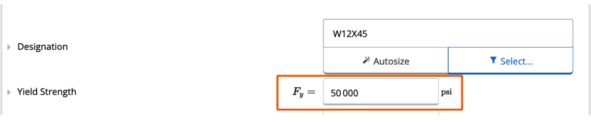
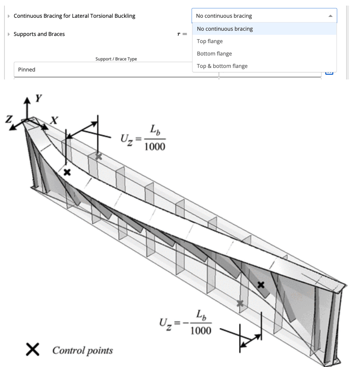
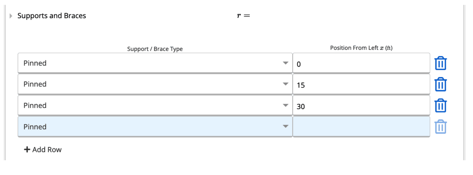
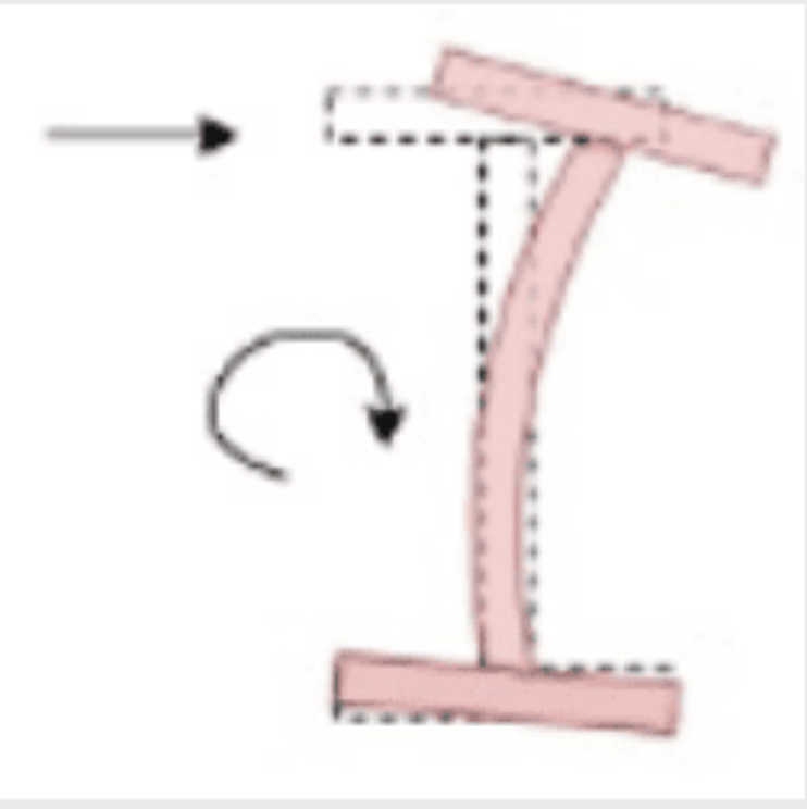
Section TypeIn Calcs.com, you will select a member from our Standard Sections Database. Note that the Standard Sections Database is constantly updated based on requests from users like yourself, and can be filtered down by Type, Max Desired Depth, and Max Desired Width. More on this in the Size and Grade section after this.Size and GradeWhen sizing a beam in Calcs.com, the two ways to find your most optimal member are by using Preferred Sections and Autosize, or by using the Member Selector within the calculator.Prior to using Preferred Sections and Autosize, you’ll need to set up your Preferred Sections in Project Details. This feature will select the most optimal/efficient member out of your preferred sections. Calcs.com will also alert you here if none of your preferred sections will pass. See screenshot below.Using the Member Selector within the calculator does not require you to have set up preferred sections. In this case, you can use as many or as few of the filters provided to see the member types you’re interested in. Notice you also see the real-time utilization percentages in green, yellow, and red showing you which beams pass or fail. This way, you can quickly use your engineering judgment if you’d like to bump up or down a size.Notice in the second screenshot below that the Member Selector is filtered to show all W-sections (I-beams) with a cross section no larger than 10in by 10in. This way, you can quickly choose the member you are most comfortable with.Yield StrengthThe yield strength of the member. Default value is based on preferred specifications outlined in the AISC Steel Construction Manual.Note that Calcs.com will default your yield strength based on the steel cross section you’ve selected. For example, if you’ve selected a W-section your yield strength will default to 50ksi. This can always be overridden by the user.Beam Plan LengthThe horizontal plan length of the beam (that is, not accounting for any slope if present).Continuous Bracing for Lateral Torsional BucklingThe top flange being continuously braced will prevent lateral torsional buckling in positive bending, and bottom flange bracing will prevent LTB in negative bending. If the beam is fully braced, then lateral torsional buckling calculations will not be performed. For dimensional lumber, the NDS 2018 (section 4.4.1) provides a requirement for a beam to be considered fully braced.For reference, selecting “No Continuous Bracing” is the most conservative option. A common scenario for selecting “Top Braced” would be a floor joist or roof rafter where the floorboards or roof itself will prevent the beam from buckling laterally.Check out the second screenshot below for a visual representation of what lateral torsional buckling means.(Reference Here)Supports and BracesPosition from leftmost of the beam of each support along the beam. Note that the first support does not have to be equal to 0 and the last support does not have to be the length of the beam (ie, a double cantilever scenario). To ignore bearing calculations, enter 0 as bearing length.You can check out this article here that walks you through how to input Supports and Braces into a beam calculator in Calcs.com.
2
Loads
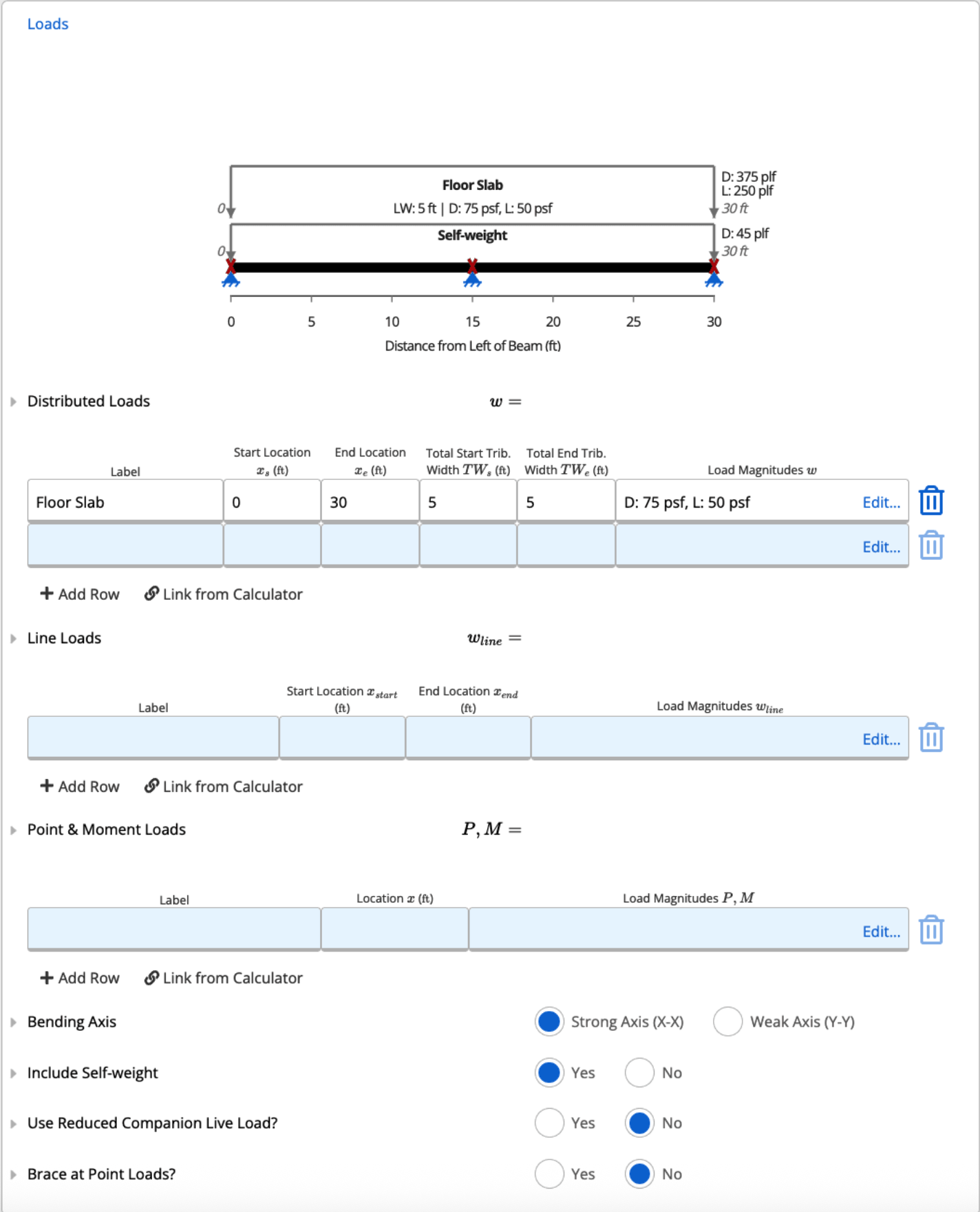
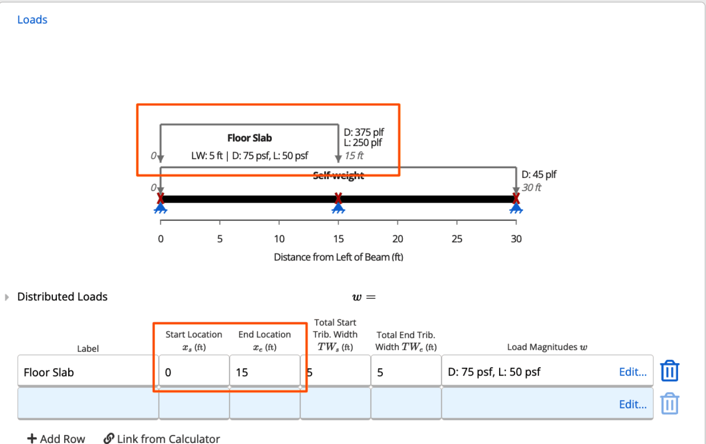
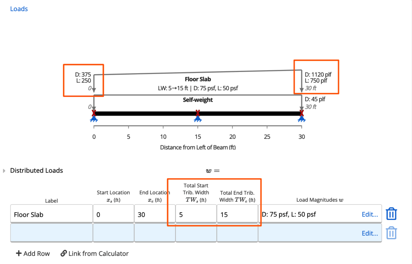
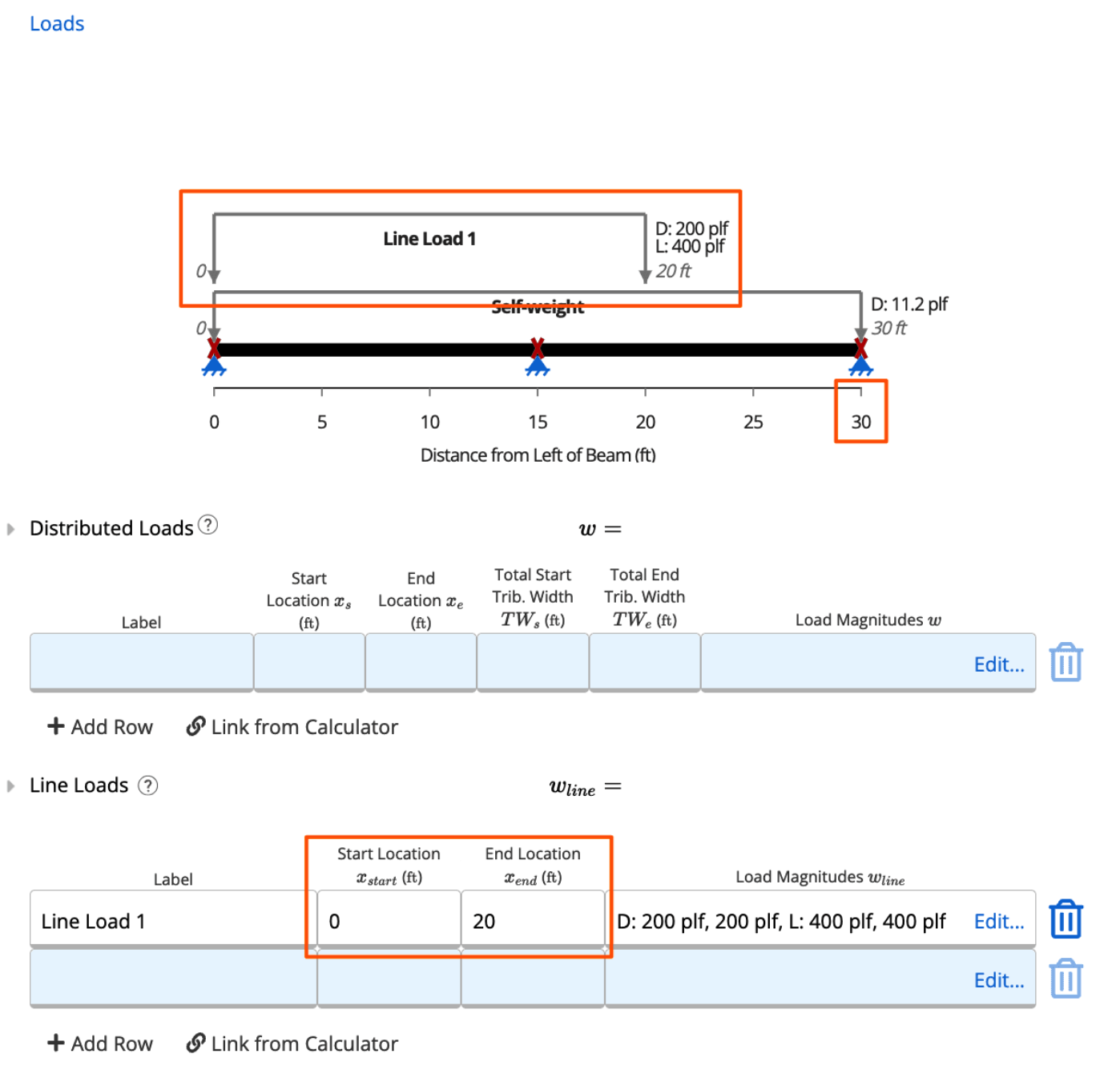
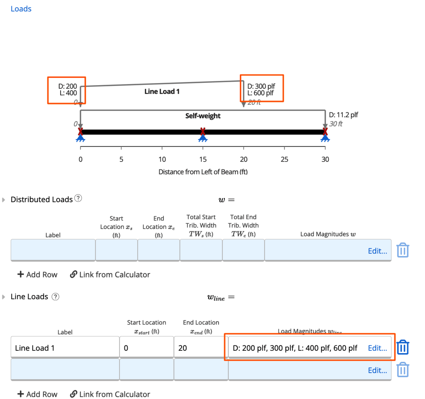
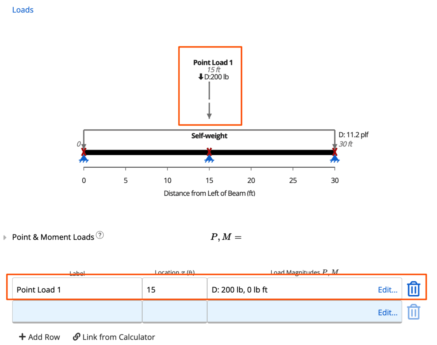
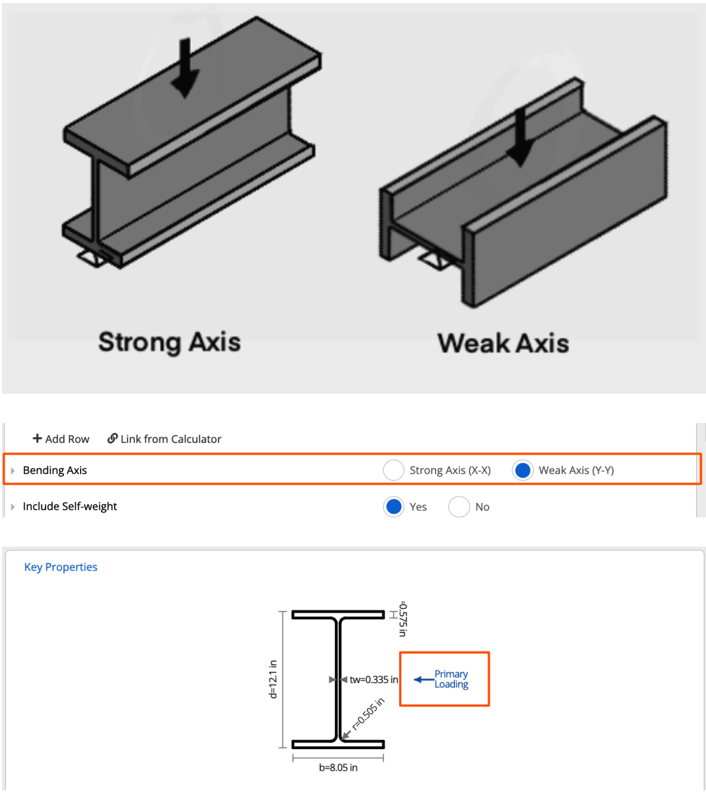
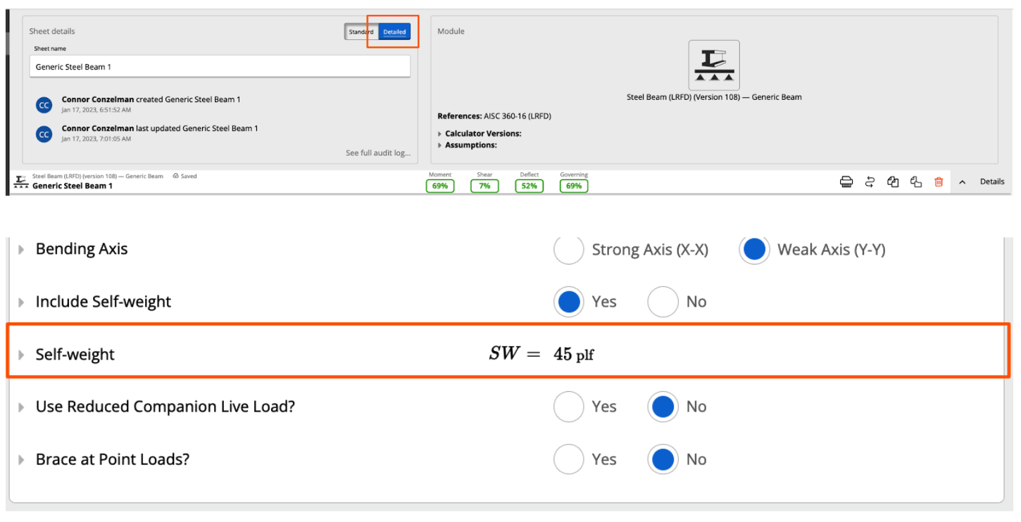
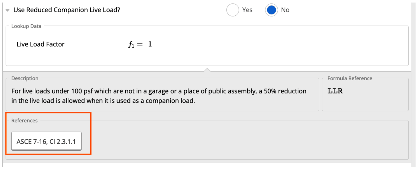
Load DiagramThe load diagram provides a live illustration of the beam and the assigned loading.Distributed LoadsA distributed load is measured in pounds-per-square-foot (psf). This load may start and end at any location. A partially distributed load (PDL), for example, would start and/or end at a location within the beam. See screenshot below.Note also that the start and end magnitudes may differ. A variable distributed load (VDL) is a triangular load, in which the start magnitude does not equal the end magnitude. You can set this by changing the tributary width at the start and at the end of the load, as shown below. An example of this would be for a hip rafter. Note that all distributed loads entered in this table are applied perpendicular to the beam. Each row of this table represents a single pair of start and end locations, but as many rows as desired may be created.You can check out this article here that walks you through how to input Distributed Loads into a Calcs.com calculator, plus this article here that expands upon the different load types.Line LoadsA line load is measured in pounds-per-lineal-foot (plf). This load may start and end at any location. A partially distributed load (PDL), for example, would start and/or end at a location within the beam. See screenshot below.Note also that the start and end magnitudes may differ. A triangular load is a load in which the start magnitude does not equal the end magnitude. Note that all line loads entered in this table are applied perpendicular to the beam. Each row of this table represents a single pair of start and end locations, but as many rows as desired may be created.Point & Moment LoadsA point load acts over a relatively small area. For example, a weight that has been hung from a ceiling or a column that is supported by a beam. This load may be of any magnitude, and may be located at any point along the beam. Note that all point loads entered in this table are applied perpendicular to the beam.A moment load causes the rotation of a member about an axis. There are few examples of pure moment loads applied in a typical structure, though the most common occurs if there is a fixed connection between a beam and column. Moment loads are also often used to idealize the effect of horizontal loads on cantilevered attachments on a beam (e.g., a satellite antenna attached to a roof rafter subjected to wind loads).Another individual beam or column bearing on or connected to this one may be linked into this table by clicking on the chain link icon on the right side of the table. Note that if you wish to connect a repeating joist or rafter, it may be easier to link these as a Line Load using the table above instead.Each row of this table represents a single location, but as many rows as desired may be created. Usually, an ‘Alternative Minimum Live Load’ will appear here by default. This Alternative Minimum Live Load, with load type ‘L2’, is NOT applied at the same time as the normal live load. For some types of surfaces, the building codes require that beams be able to support at least a minimum concentrated live load, regardless of the normal live load, and that is this value. If it is blank (zero), then the default surface type you have selected in your Project Defaults does not require an alternative minimum live load.Bending AxisChoose whether the member is loaded such that it bends about the x or y axis; X-X refers to the axis which has the higher moment of inertia (“joist orientation”) whereas Y-Y refers to the weaker moment of inertia (“plank or flat orientation”). Notice in the second and third screenshots how this field impacts your beam loading in “Summary”.Include Self-weightChoose whether or not to include the weight of the member being analyzed in the calculations. By default, self-weight is considered in all calculations. However, many span tables and design guides instead include self-weight into the design dead load, in which case leaving self-weight on in Calcs.com may lead to a small discrepancy.As a tip - you can turn on “detailed mode” in your wood beam calculator and see the self weight of your beam in the loads section of your calculator.Use Reduced Companion Live Load?For live loads under 100 psf which are not in a garage or a place of public assembly, a 50% reduction in the live load is allowed when it is used as a companion load. Note that Calcs.com will tell you which section of the ASCE this field applies to in the screenshot below.Brace at Point Loads?Choose whether or not to add braces against lateral torsional buckling at point loads. An applied load on a beam can cause lateral displacement and rotation about the plan of the section. Lateral restraints/braces aim to prevent this by restraining the compression flange. Secondary beams are commonly used as discrete lateral restraints where those secondary beams provide lateral support to the primary beam at their connection points.
3
Design Conditions
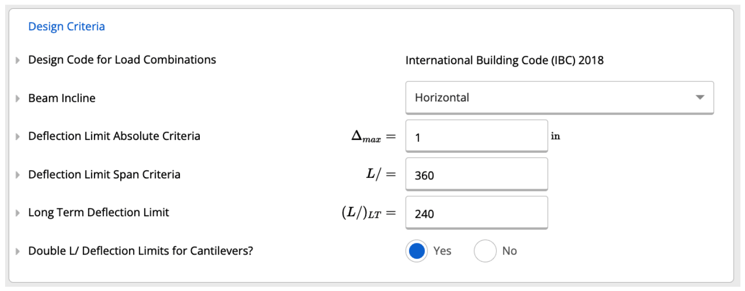
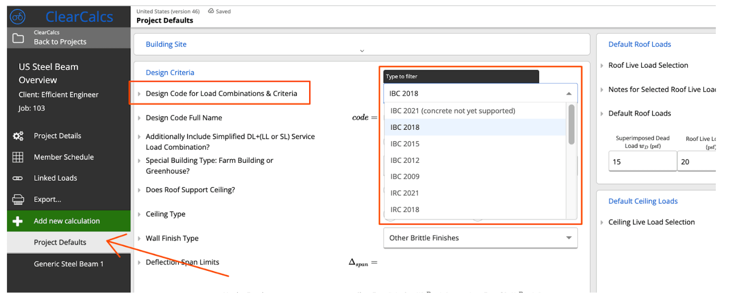
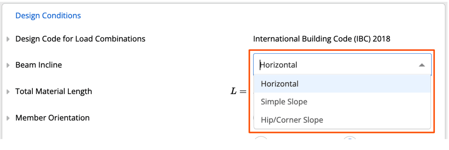
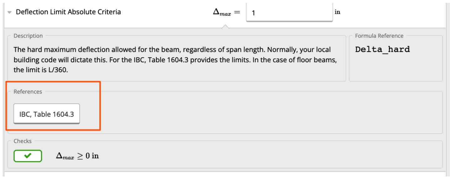
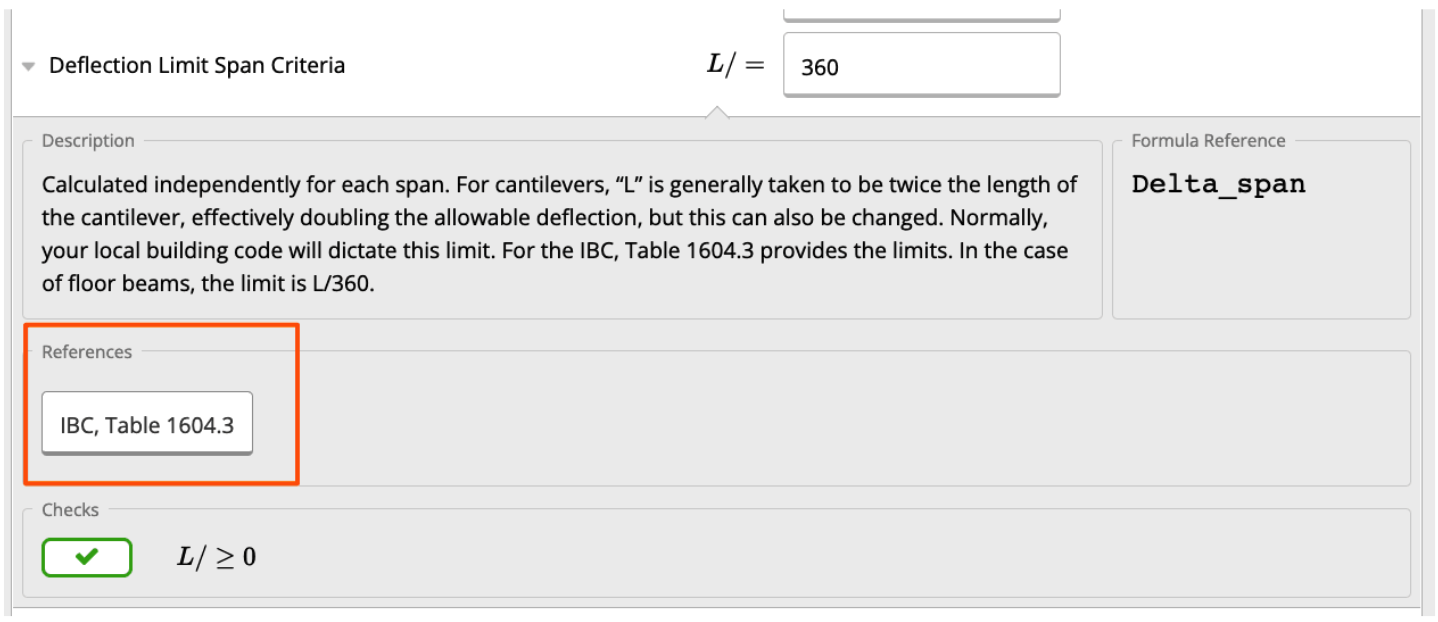
As a pro tip, you likely won’t need to change any of the inputs in this Design Conditions section of your calculator since they’re defaulting per the calculator preset you’ve selected and the design code you’ve selected. However, it’s always good practice to confirm these values and assumptions are correct for your beam.Design Code for Load CombinationsThis may be changed in the Project Defaults sheet for this project. It cannot be changed in individual calculations. See screenshot below for where you can change this in Project Defaults, and check out this article here for more information on US Project Defaults.Beam InclineIf your beam is on an incline or a hip/corner slope, this is where you’ll tell Calcs.com. This field will default based on the steel beam preset you’ve selected.Deflection Limit Absolute CriteriaThe hard maximum deflection allowed for the beam, regardless of span length. Normally, your local building code will dictate this.Some common examples when you’ll use this absolute limit is when you’re designing a floor joist in an expensive home, or when you’re designing a header above french doors. In both cases, you may want to ensure the beams won’t deflect more than 0.25” no matter what your “L/” checks show you.Deflection Limit Span CriteriaCalculated independently for each span. For cantilevers, “L” is generally taken to be twice the length of the cantilever, effectively doubling the allowable deflection, but this can also be changed. Normally, your local building code will dictate this limit. For the IBC, Table 1604.3 provides the limits. In the case of floor beams, the limit is L/360.Long Term Deflection LimitCalculated independently for each span. For cantilevers, “L” is generally taken to be twice the length of the cantilever, effectively doubling the allowable deflection, but this can also be changed. Normally, your local building code will dictate this limit. For the IBC, Table 1604.3 provides the limits. In the case of floor beams, the limit is L/360.Loads that will be included in your Long-term Deflection calculations are:
Creep component of the dead load (50% of the instant deflection in most cases) and the full live load
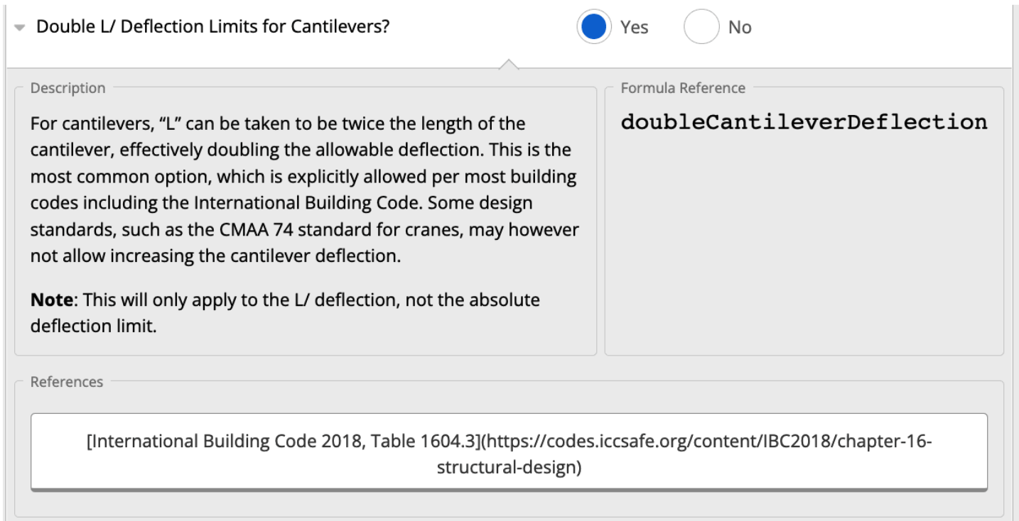
Double L/ Deflection Limits for CantileversFor cantilevers, “L” can be taken to be twice the length of the cantilever, effectively doubling the allowable deflection. This is the most common option, which is explicitly allowed per most building codes including the International Building Code. Some design standards, such as the CMAA 74 standard for cranes, may however not allow increasing the cantilever deflection.Note: This will only apply to the L/ deflection, not the absolute deflection limit.
4
Summary
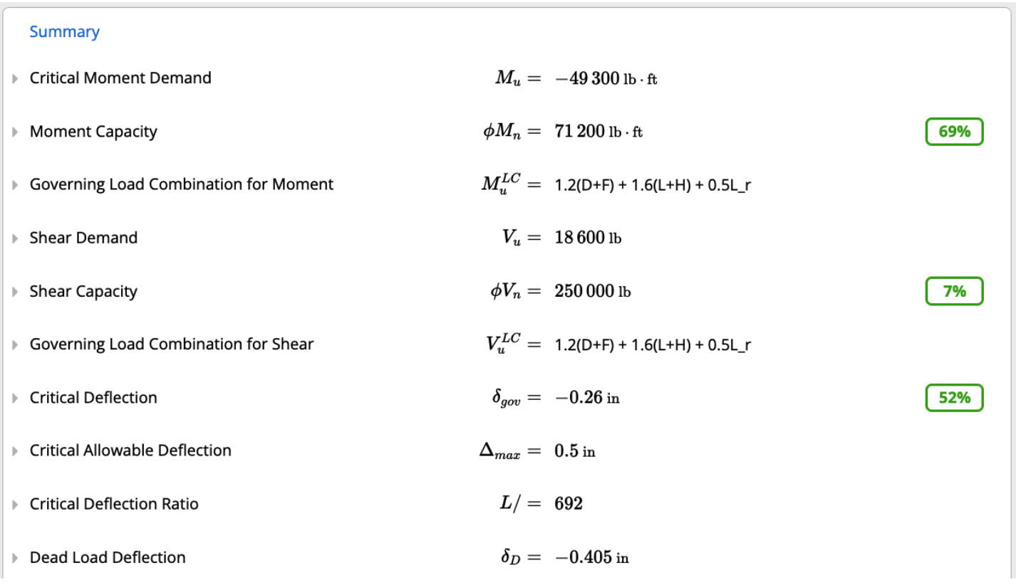
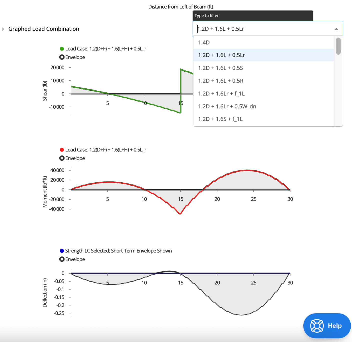
In this Summary section, Calcs.com is looking at your utilization percentages (i.e., demand divided by capacity of your beam) for Moment, Shear, Bearing, Short-Term Deflection, and Long-Term Deflection. Note as well that Calcs.com is automatically calculating the worst-case (governing) load combination.Finally, the right side of the Calcs.com screen will also show you your shear, moment, and deflection diagrams. The black line on the graphs (the “envelope”) show the worst-case (governing) load combination, while the green, red, and blue lines in the graphs show the graphed load combination. This can be modified in the dropdown shown in the first screenshot below.Interested in learning more about the US Steel Beam calculator? Check out the links below:
What design method and code standard does this calculator use?
This calculator uses the Allowable Strength Design (ASD) method per AISC 360-22. Service-level demands from ASD combinations are compared to allowable strengths Rn / Omega for bending (Omega_b = 1.67) and shear (Omega_v = 1.67).
What are the key inputs?
Key inputs include the steel section (W, S, C, HSS, angle, or custom), yield strength Fy, span lengths and support conditions, service-level loads (dead, live, snow, wind) with tributary widths, unbraced length for LTB, and deflection limit criteria for live load, total, and DL+(LL or SL) checks.
What does it check or output?
The calculator checks service moment demand versus allowable moment (AISC 360-22 Chapter F), service shear versus allowable shear (Chapter G), and three deflection limits. The summary shows the governing ASD load combination for moment and shear, support reactions for load linking, and deflection ratios.
Can it handle continuous spans and lateral-torsional buckling?
Yes, continuous spans, cantilevers, and simple spans are supported with unlimited loads. Lateral-torsional buckling is checked per AISC 360-22 Chapter F using the unbraced length Lb and the Cb gradient factor. Section classification per B4 determines whether FLB or WLB reductions apply.
When should I use the ASD version versus the LRFD version?
Use ASD when your project applies service-level load combinations (D+L, D+S, etc.) or when the design basis requires ASD. Use the LRFD version (steelBeamAISC360-22) when using factored strength-level combinations (1.2D+1.6L etc.). Both reference AISC 360-22 and produce equivalent designs at the strength limit; the difference is in load combination philosophy and resistance factors.
Does this calculator support load linking with column and footing calculations?
Yes, beam reactions at supports link directly to connected column and footing calculations in the same project. When span length, loads, or member size changes, all connected calculations update automatically, no manual re-entry.