

United StatesACI 318-19

Design rectangular concrete columns to ACI 318-19 with customizable longitudinal bar layout. Checks include pure axial capacity, X- and Y-axis P-M interaction, biaxial bending via the Bresler method, and moment magnification for slender columns. Axial reactions from beams above link automatically.
Background
The Concrete Column overview outlines the key properties, reinforcement, loads, and capacities calculated in the summary. You can learn how each of the properties are calculated within your calculation by opening your project in detailed view, or by selecting the arrow on the side of the widget to view the equations, references and descriptions in debug mode. Project default values can also be used to link code standards, defined default loads, properties, or design criteria so that defined values are automatically pulled to your beam design. You can also check out a video for the calculator overview hereMethod & scope
See the exact clause
Calculation method
The Rectangular Concrete Column (ACI 318-19) calculator uses the same fundamental design approach as the ACI 318-14 version, interaction diagrams from the rectangular stress block, Bresler biaxial method, and non-sway moment magnification. The core structural logic is equivalent between the two editions.Interaction diagram
The P-M interaction diagram is generated using εcu = 0.003 and the ACI rectangular stress block factor β1 per ACI 318-19 Table 22.2.2.4.3, which varies with f’c:- f’c ≤ 4000 psi: β1 = 0.85
- f’c > 4000 psi: β1 = 0.85, 0.05 × (f’c, 4000) / 1000 ≥ 0.65
Slenderness (non-sway frame)
For slender non-sway columns, moment magnification is applied via the ACI magnification method: Mc = δs × Mu where δs = Cm / (1, Pu / 0.75Pc) with Cm = 0.6 + 0.4 × (M1/M2) derived from the user-entered end moment ratio.Biaxial bending (Bresler method)
The Bresler reciprocal load method determines the biaxial capacity: 1/φPn,biaxial = 1/φPnx + 1/φPny, 1/φPo The biaxial utilization Pu / φPn,biaxial ≤ 1.0 must be satisfied. The calculator conservatively evaluates the interaction at the maximum simultaneous Pu, Mu,x, and Mu,y from the governing LRFD combination. ACI 318-19 clause reference updates (φ factor transitions in Section 21.2, shear table changes) are reflected, but the structural design logic confirmed from the template JSON is equivalent to the ACI 318-14 version for the checks covered.How to use it
1
Key Properties
The column geometry and concrete strength can be defined under the key properties. You can specify the total height, or length of the column here. The buckling length factor for both the x and y axis can also be specified. A buckling length factor of 1 is generally conservative for non-sway frames and nonconservative for sway frames.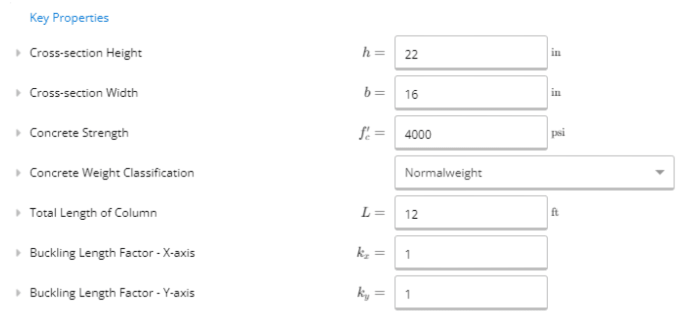
2
Reinforcement
The longitudinal reinforcement can be defined by specifying the bar size and reinforcement strength. By default, the calculator considers one bar at each corner. To add more reinforcement along the edges, you can specify them under the “Additional Reinforcement Bars (per side). For example, if we wanted 4 bars along each of the faces, you would input 2, since one bar is already counted at the corners. The concrete cover also needs to be defined, this should be a minimum of 1.5 in, as per ACI 318-19. The minimum size and spacing for ties are also calculated.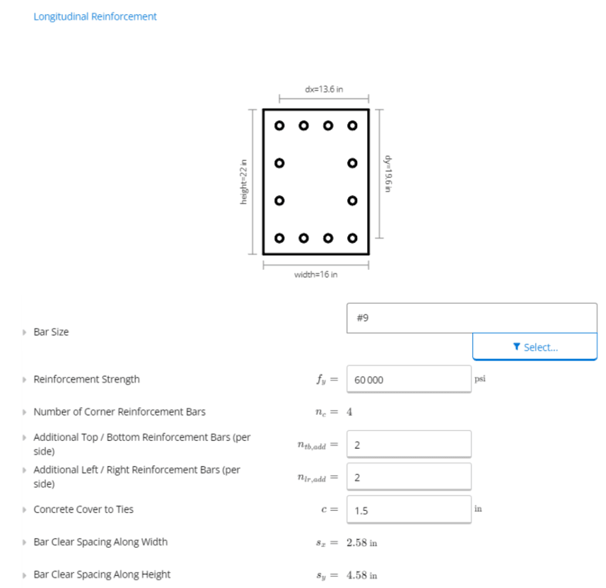
3
Loads
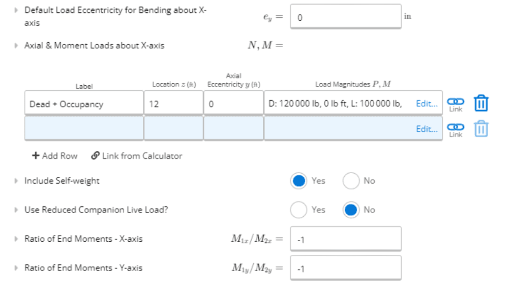
Calcs.com has a variety of loading conditions that can be entered. To start, we can specify a default load eccentricity for bending about the X-axis, or we can manually change this value per load in the table. The Axial & Moments Loads about X-axis table takes into account the unfactored load conditions. These can be defined as dead, live, snow, or wind loads for example, and can be applied as a vertical load or a moment load. The location these are applied at is measured from the bottom of the column. There is also an option to use the reduced companion live load (refer to IBC Clause 1605).The ratio of end moments can also be defined in these properties. This is a way of comparing bending moments at each end of the column, where a column with single curvature (i.e. a beam) indicates a negative ratio, and a column with double curvature (i.e. a shell) has a positive ratio, since the moments at each end are rotating in the same direction. This ratio should always be between -1 and 1. This ratio in particular impacts the calculation of slenderness effects and moment magnification.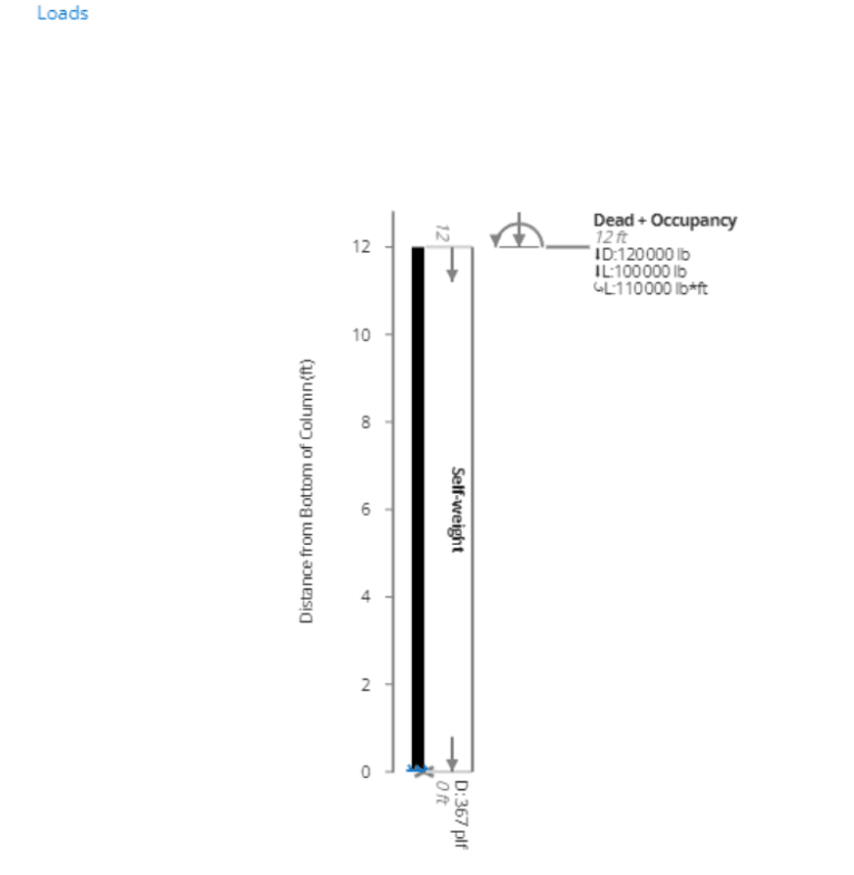
4
Y-Axis Moment Loads
This input works the same way as the table for loads in the X-axis, however should consider that these will be applied in the perpendicular direction. Any axial loads defined here will be added together with the axial loads entered in the equivalent table for X-axis loads.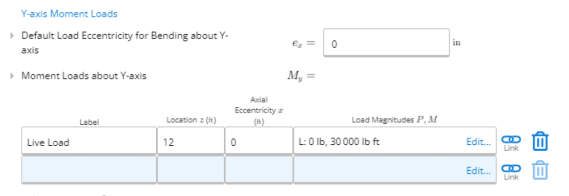
5
Results
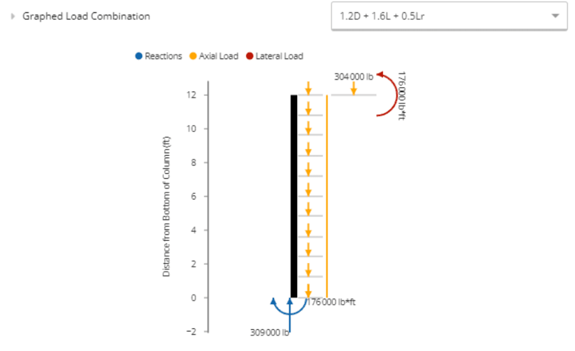
In our summary, we can see axial and moment loads are computed, with the interaction checks and biaxial bending checks also being carried out. All capacities are factored in the summary, based on the strength reduction factor. Our graphed load combinations are shown as well.The pure axial load capacity considers the squash load and other factors. This is for non prestressed members, taking into account the concrete strength and area, added to the steel yield strength and area.The axial interaction capacity looks at combined axial and bending, taking the sum of forces from concrete and the reinforcement. Calcs.com checks for this in both the X and Y directions. Next, we have moment capacity checks in both directions, where the nominal column capacity is multiplied by the eccentricity distance.The bi-axial bending is checked as per the Bresler method, which only applies when the design axial load is under 10% of the squash load.A passing design will be indicated with a utilization below 100%. If your design is failing, you can hover over the error to see where exactly the error is occurring. To increase capacity, typical solutions include using larger column dimensions, higher concrete strength, or more reinforcement.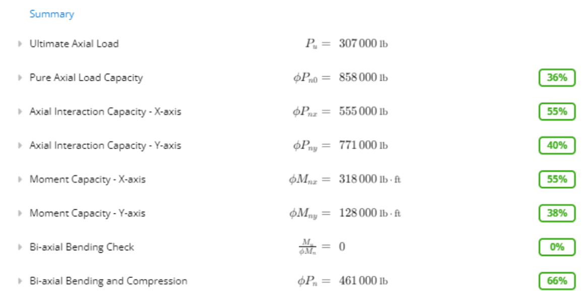
Common questions
What design method and standard does this calculator follow?
What design method and standard does this calculator follow?
Strength Design Method (LRFD) per ACI 318-19. LRFD load combinations from ASCE 7 determine the governing factored axial load Pu and biaxial moments Mu,x and Mu,y. ACI 318-19 Section 22 provisions govern the interaction diagram and slenderness checks.
What are the key inputs?
What are the key inputs?
Column cross-section dimensions (h and b, in inches), concrete strength f’c (psi), lightweight concrete factor λ, column height L (ft), effective length factors K for X and Y axes, end moment ratio Cm, longitudinal bar size and count (corner bars plus optional additional bars per face), reinforcement yield strength fy (40-80 ksi), clear cover to ties, load eccentricities, and factored loads by type (D, L, Lr, S, R, W, Ev, Eh) on both axes.
How is biaxial bending handled?
How is biaxial bending handled?
The Bresler reciprocal load method is used: 1/φPn,biaxial = 1/φPnx + 1/φPny, 1/φPo. φPnx and φPny are uniaxial capacities at the acting moments about each axis; φPo is the pure axial capacity. The biaxial utilization Pu / φPn,biaxial ≤ 1.0 must be satisfied.
How does slenderness affect the design?
How does slenderness affect the design?
For slender columns in non-sway frames (klu/r > 22), moment magnification is applied: Mc = δs × Mu where δs = Cm / (1, Pu/0.75Pc). Cm is derived from the user-entered end moment ratio M1/M2. Sway vs. non-sway classification and bracing condition are entered by the user.
Does the calculator check shear?
Does the calculator check shear?
Shear is flagged as a warning, it is not numerically checked. For columns with significant lateral loads, shear capacity should be verified separately per ACI 318-19 Table 22.5.5.1.
Does this calculator support load linking with beam calculations?
Does this calculator support load linking with beam calculations?
Yes, axial load reactions from connected beam calculations link directly to this column. When loads change in any upstream beam, the column’s axial demand updates automatically, keeping the full gravity load path consistent.
Next steps
Design a Concrete Beam to ACI 318-19
Design rectangular concrete beams and T-beams to ACI 318-19 across unlimited spans. Checks flexure, shear, and short- and long-term deflection.
Concrete Column Calculator to ACI 318-19 - Worked Example
Worked example: an axially loaded concrete column to ACI 318-19, solving nominal compressive strength and checking moment and interaction utilization.