

United StatesNDS 2024 (ASD)

The Calcs.com timber column ASD calculator to NDS 2024 enables the fast and accurate design of wood columns and studs to American standards. With support for dynamic load linking between beams and columns, easily design accurate and quality engineered columns, and select from our database of thousands of US wood sections.
The Calcs.com Timber Column Calculator allows users to design timber columns by specifying the desired load cases and dimensions of the column. In this article, each section of the calculator will be explained followed by a few worked examples.
The Timber Column Calculator has 4 main sections
- Key Properties
- Design Conditions
- Loads
- Summary and Graphs
Worked example
Task 1
Design a timber stud with the following characteristics- for residential application
- 12ft in height with noggings (along the weak axis) every 3ft
- member type: 2x8 Douglas Fir stud
- fixed base and a roller support at the top
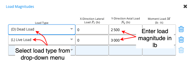
- an axial load at the top: 1000lbs/ft dead load and 1200lbs/ft live load with 2.5ft stud spacing
- assume zero eccentricity
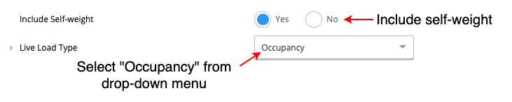
- include self-weight
- assume dry service conditions and temperature conditions to be <100 degrees F
Method & scope
Method
Task 2
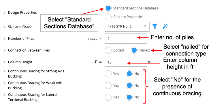
Design a timber column with the following characteristics- for residential application
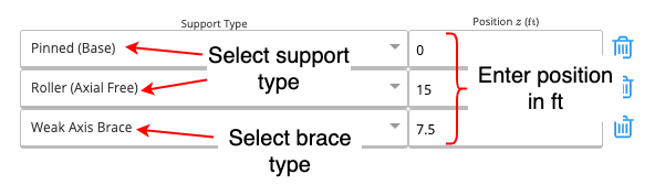
- 15ft in height with a weak axis brace halfway along the column
- fixed support at the bottom and roller support at the top
- 2 piles nailed together
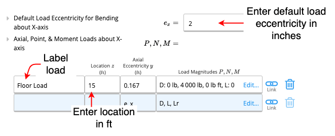
- Assume default load eccentricity to be equal to 2 inches
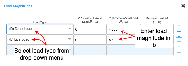
- Axial load at the top: 4000lb dead load and 8500lb live load
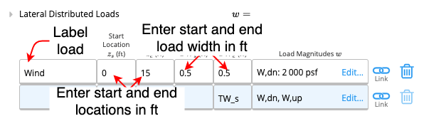
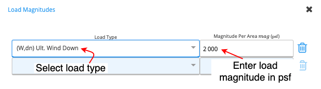
- A laterally distributed wind load of 2000psf from top to bottom of the column (load width 0.5ft)
- include self-weight
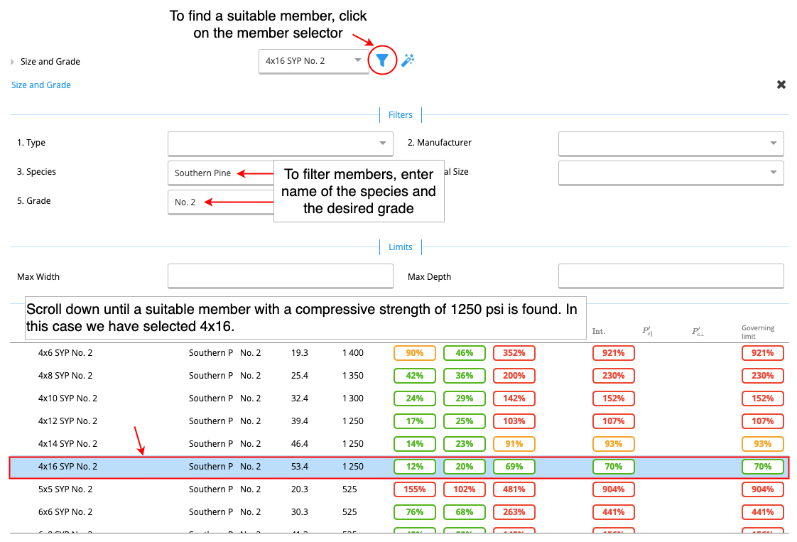
- select a No.2 grade Southern Pine Member with a compressive strength of 1250psi
- assume dry service conditions and temperature conditions to be <100 degrees F
Method

 |  |
See the exact clause
What it calculates
Column axial loads link from connected beam calculations automatically, update a span or load once and every downstream column updates. Design wood columns and studs to NDS 2024 ASD with compression stability (Cp), biaxial bending interaction (NDS Eq. 3.9-3), and bearing checks. Columns are load-path critical members. An under-designed post or stud transfers risk straight to the footing and foundation below, and errors are difficult to catch without a full code-compliant check. NDS 2024 ASD is the method required by the current IBC for jurisdictions that have adopted the 2024 code cycle. This calculator runs every required check, column stability, combined bending and axial interaction, and bearing, in one place, with load linking that keeps the full load path consistent when spans or loads change.Calculation method
The Wood Column (ASD, NDS 2024) calculator designs sawn lumber, glulam, and structural composite lumber (SCL) columns and studs using Allowable Stress Design per the 2024 National Design Specification for Wood Construction. Reference design values are drawn from the NDS 2024 Supplement (Tables 4A, 4B, 4C, 4D, 4E, 4F) and adjusted by all applicable factors before each limit state is evaluated.Design method
All reference design values (Fc, Fb, Ft, Fv, Fc⊥) are multiplied by applicable adjustment factors to obtain allowable values. The governing utilization ratio across all checks must not exceed 1.0. The primary design basis is NDS 2024 Chapters 3 and 4, with column stability governed by NDS 2024 Section 3.7.Adjustment factors
The key adjustment factors applied by this calculator are:- CD (load duration factor), amplifies or reduces allowable stress based on the duration of the controlling load combination; short-duration loads (wind, seismic) allow higher stress than sustained dead loads
- CM (wet service factor), reduces allowable values when in-service moisture content exceeds 19% for sawn lumber or 16% for glulam and SCL
- Ct (temperature factor), reduces values for members subject to sustained elevated temperatures above 100°F
- CF (size factor), modifies Fb, Ft, and Fc for sawn lumber based on cross-section depth and width per NDS 2024 Supplement tables
- Ci (incising factor), applied when preservative treatment requires incising, reducing most reference values per NDS 2024 Table 4.3.8
- Cr (repetitive member factor), increases Fb by 1.15 when three or more parallel members at 24 in. or less spacing share loads through adequate sheathing
- Kf (built-up column factor), reduces the effective column stability factor for nailed or bolted multi-ply columns relative to an equivalent solid or glulam section
Compression checks
Two independent compression capacity checks are performed, one for each principal axis, to account for different effective lengths and bracing conditions: F’c,x = Fc × CD × CM × Ct × CF × Ci × Cp,x F’c,y = Fc × CD × CM × Ct × CF × Ci × Cp,y The column stability factor Cp is computed per NDS 2024 Eq. 3.7-1, which is a function of the Euler critical buckling stress FcE = 0.822 E’min / (Le/d)², the adjusted reference compressive stress F*c (all factors except Cp), and the parameter c (0.8 for sawn lumber, 0.9 for glulam and SCL). A separate Cp is calculated for each axis using the corresponding effective slenderness ratio. Utilization (X-axis): fc / F’c,x ≤ 1.0 Utilization (Y-axis): fc / F’c,y ≤ 1.0Bending and shear checks
Biaxial bending is evaluated independently on each principal axis: F’b = Fb × CD × CM × Ct × CF × Ci × CL × Cr For glulam and SCL members, the volume factor CV replaces CL for strong-axis bending (the lesser of the two governs). The beam stability factor CL accounts for lateral-torsional buckling per NDS 2024 Appendix E; for columns with adequate bracing on both axes, CL = 1.0. Shear is checked on each axis: F’v = Fv × CD × CM × Ct × Ci Utilization (shear): fv / F’v ≤ 1.0Combined loading
For members subject to simultaneous axial compression and biaxial bending, the calculator evaluates NDS 2024 Eq. 3.9-3 and 3.9-4: (fc / F’c)² + fb,x / (F’b,x × [1, fc / FcE,x]) + fb,y / (F’b,y × [1, fc / FcE,y, (fb,x / FbE)²]) ≤ 1.0 The denominator terms [1, fc / FcE] amplify the effective bending demand to account for the P-delta effect of axial load on lateral deflection. The summary utilization is the maximum across both interaction equations. For members subject to tension and bending, NDS 2024 Eq. 3.9-1 and 3.9-2 are evaluated: ft / F’t + fb / F’b ≤ 1.0Bearing
Bearing is checked at both member ends:- Parallel to grain (F’c,||): applies where the column end bears on a plate or sill aligned with the grain direction
- Perpendicular to grain (F’c⊥ = Fc⊥ × CM × Ct × Ci × Cb): applies where load transfers across the grain, such as at a sill plate or beam seat
NDS 2024 reference design values
Reference design values are sourced from the NDS 2024 Supplement tables for the selected species, grade, and size classification. Where NDS 2024 values differ from NDS 2018 for specific species-grade combinations, the 2024 values govern. If your project requires NDS 2018 compliance, use the timberColumnASD calculator instead.How to use it
1
Key Properties
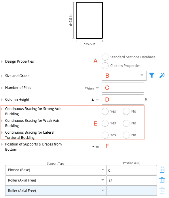
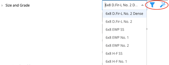
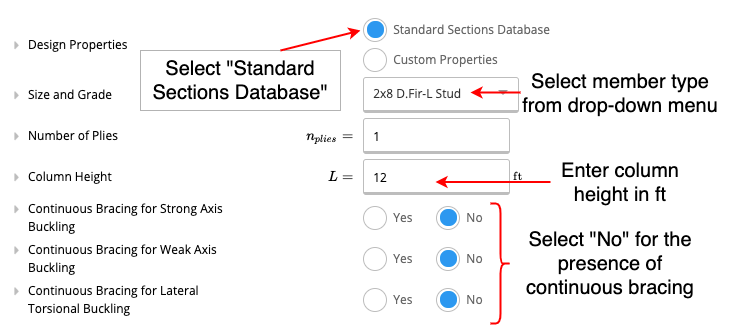
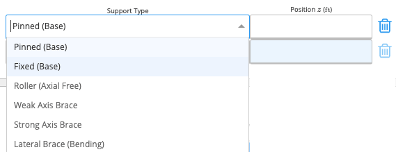
- Continuous bracing for strong (major) axis buckling
- Continuous bracing for weak (minor) axis buckling
- Continuous bracing for lateral-torsional buckling
2
Design Conditions
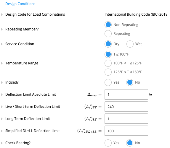
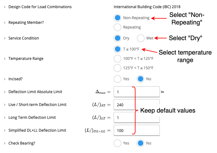
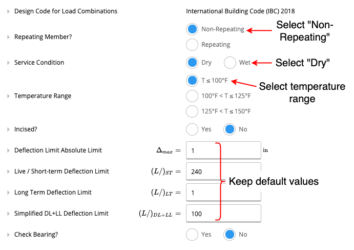
- Repeating Member: A member is considered repeating if multiple members are repeating at less than 24” spacing under a load-distributing element, such as a floor or roof.
- Service Condition: The user can select if the service condition is ‘dry’ or ‘wet.’ It is considered wet if the moisture content of wood will exceed 19% for an extended time. Most often applies only to exterior use.
- Temperature Range: The user can specify the range of sustained temperature exposure from the options given.
- Incised: A member is incised if lumber is incised to a maximum depth of 0.4” and a maximum length of 3/8”, with a density of incision up to 1100/ft².
- Deflection Limit Absolute Limit: This is the hard maximum deflection allowed for the beam, regardless of span length. Normally, the local building code will dictate this. This quantity must be specified in inches(in).
- Check Bearing: If this is set to yes, a bearing check will be performed assuming the column bears on a perpendicular member of the same material and grade.
3
Loads
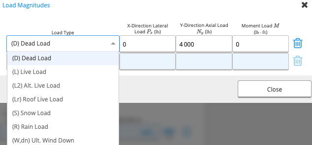
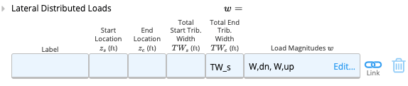
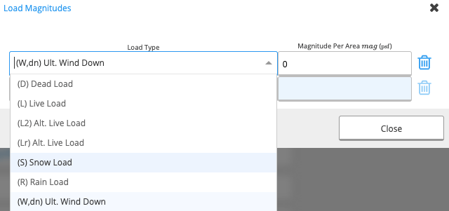
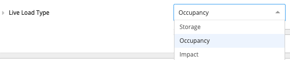

4
Summary & Graphs
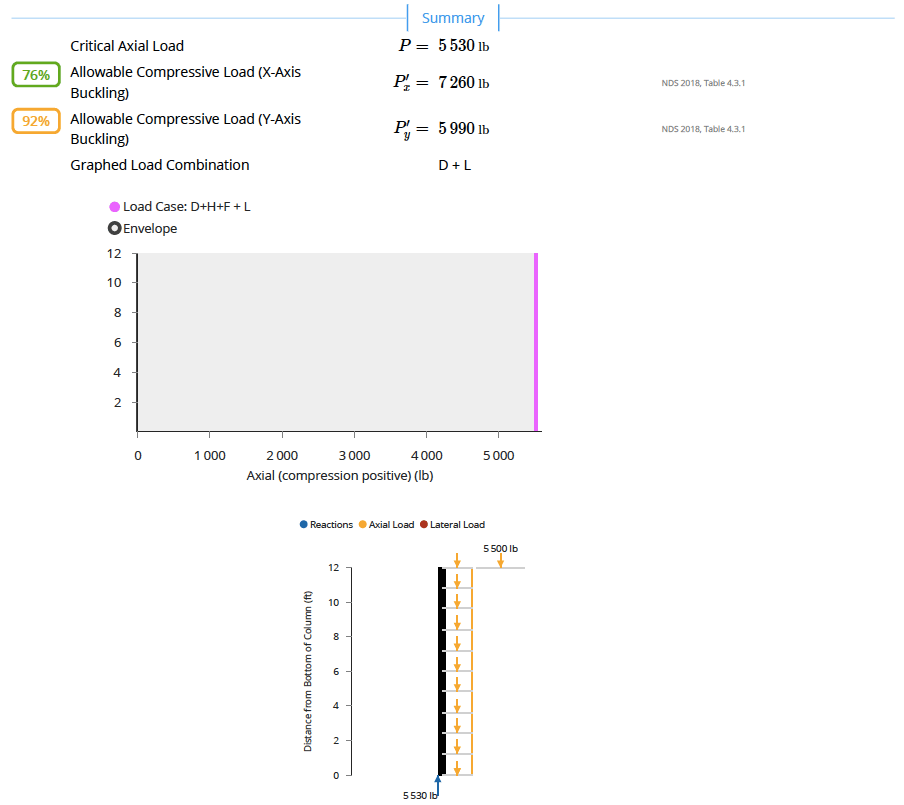
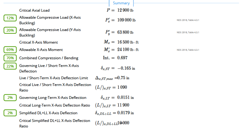
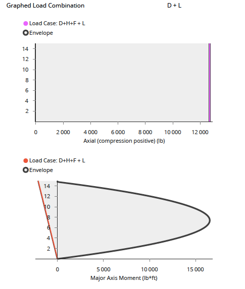
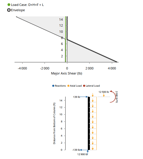
The summary section the key parameters of your calculation will be outlined.In the graphs section, the user can select the load combination that they would like the see in their graph (e.g.: D+L).A sample of the summary and graphs produced during calculations can be seen in the examples given below.
US Wood Column: Overview
US Wood Column: Example
Available presets
Each preset opens the calculator with a typical setup already entered.Common questions
What design method and standard does this calculator use?
What design method and standard does this calculator use?
This calculator designs wood columns and studs to the 2024 National Design Specification for Wood Construction (NDS 2024) using Allowable Stress Design (ASD). Adjusted allowable compression stress F’c and the column stability factor Cp are computed from NDS 2024 Table 4A/4B reference design values multiplied by all applicable adjustment factors.
What inputs does the wood column calculator require?
What inputs does the wood column calculator require?
Key inputs include column height, effective length factors (Ke) for both axes, section type from the US wood section library or custom entry, number of plies, applied loads (axial and biaxial bending), and service conditions (moisture, temperature, incising). Dynamic load linking from beam calculators is supported to eliminate manual load transfer.
What checks and outputs does the calculator provide?
What checks and outputs does the calculator provide?
Outputs include the column stability factor Cp, adjusted allowable compressive stress F’c, bending interaction ratio per NDS 2024 Eq. 3.9-3, combined bending and axial utilization, and bearing capacity check where applicable. Utilization ratios for each limit state are shown, values at or below 1.0 indicate adequate capacity.
How does this calculator differ from the NDS 2018 version?
How does this calculator differ from the NDS 2018 version?
The NDS 2024 version applies reference design values and adjustment factors from the 2024 edition of the NDS Supplement. For some species and grades, tabulated values differ from NDS 2018. If your jurisdiction has adopted the 2024 IBC, which references NDS 2024, use this calculator. The timberColumnASD calculator is for projects requiring NDS 2018 compliance.
How do I set effective length factors for my column?
How do I set effective length factors for my column?
Set Ke for each axis based on your end conditions: Ke = 1.0 for pin-pin, 0.65 for fixed-fixed, 0.8 for pin-fixed, and 2.1 for free-fixed (cantilever). NDS Appendix G provides guidance for common conditions. For stud walls with sheathing providing lateral restraint on the weak axis, Ke is often taken as 1.0 on the strong axis and 1.0 on the weak axis with the full wall height as the unbraced length.
Can I use this calculator for multi-ply built-up columns?
Can I use this calculator for multi-ply built-up columns?
Yes. Enter the number of plies in the built-up column input. The calculator applies the built-up column factor Kf per NDS 2024, which reduces the effective column stability factor Cp for nailed or bolted multi-ply assemblies relative to a solid or glulam section of the same cross-section. This correctly models the reduced buckling capacity of doubled or tripled studs.
Next steps
Design a Wood Beam (ASD) to NDS 2024
Design wood beams to NDS 2024 (ASD): bending, shear, bearing and three deflection limits, with multi-ply and flitch plate options.
Design a Wood Column (LRFD) to NDS 2024
NDS 2024 LRFD wood column. Stability (Cp), combined bending and axial (NDS 3.9), and bearing with φc, KF, λ. Load reactions link from connected beams.
Design a Wood Member (Design Only - ASD) to NDS 2024
Design wood truss chords and frame members to NDS 2024 ASD. Combined axial and biaxial bending per Eq. 3.9-3, stability factor Cp, all adjustment factors.
Wood Column to NDS 2018 - Validation Examples
Wood Column to NDS 2018 - Validation Examples