

United StatesIBC 2024ASCE 7-22ACI 318-19

Design restrained (basement) retaining walls to IBC 2024, ASCE 7-22, and ACI 318-19. Rankine theory with at-rest or active soil pressure, combined axial-flexural stem design, footing flexural checks, and optional shear key. Input dead and live loads at the wall top for more realistic restraint forces than deflection-only workflows.
Background
The Calcs.com Restrained Retaining Wall Calculator allows you to quickly design basement retaining walls to IBC 2021, ASCE 7-16, and ACI 318-19. This calculator assumes the absence of shear keys, no inclination of soil behind the structure, and excludes wind or earthquake loads. All concrete detailing assumes that the rebar is continuous over the entire height of the wall and should be checked separately. This calculator is similar to the cantilever retaining wall calculator, however does not check for overturning as it is fully prevented by restraints at the time. This could be restrained by a floor diaphragm, for example.Method & scope
What it calculates
Design restrained (basement) retaining walls to IBC 2024 and ACI 318-19 with combined axial-flexural stem design, the check that deflection-only workflows miss. Input dead and live loads at the wall top for realistic restraint forces. Covers basement configurations the cantilever retaining wall calculator cannot handle, with Rankine at-rest or active pressure and an optional shear key. Input dead and live loads directly at the top of the wall stem to analyze combined axial-flexural effects per ACI 318-19, producing more realistic restraint forces than deflection-only workflows. Example: an 11-foot wall without axial input may yield restraint forces exceeding 800 plf; with axial input, designs align with actual construction scenarios. Covers basement configurations the cantilever retaining wall calculator cannot handle.Calculation method
The Restrained (Basement) Retaining Wall (IBC 2024) calculator designs propped retaining walls, typically basement walls braced at the top by a floor diaphragm, per IBC 2024, ASCE 7-22, and ACI 318-19. Rankine theory is used for lateral earth pressure and the wall stem is analyzed as a propped cantilever with combined axial and lateral load.Lateral earth pressure (Rankine theory)
Lateral soil pressure is estimated using Rankine theory. Two modes are supported:- At-rest (K_0 = 1, sin phi), for walls that cannot rotate or translate at the top, which is the typical condition for basement walls braced by a floor diaphragm
- Active (K_a = tan²(45°, phi/2)), for walls where top movement cannot be prevented
Stability checks
Sliding resistance is verified at the footing base: FS_sliding = F_resist / F_slide ≥ 1.5 where F_resist combines base friction and passive soil resistance at the toe, plus optional shear key passive resistance. Maximum bearing pressure q_max is checked against the allowable bearing capacity q_a.Stem combined axial-flexural design (ACI 318-19, Cl. 22.4 and 22.2)
The wall stem is designed as a one-way propped vertical slab. Dead and live loads at the top of the wall are combined with the lateral soil load to produce combined axial force N* and bending moment M* at the critical section. Capacity checks: utilization (flexure) = M_u,stem / (phi × M_n,stem) ≤ 1.0 utilization (axial) = N_u,stem / (phi × N_n,stem) ≤ 1.0 utilization (shear) = V_u,stem / (phi × V_n,stem) ≤ 1.0 Combined axial-flexural interaction is checked per ACI 318-19 Cl. 22.4, ensuring the design accounts for the interaction between vertical loads and the lateral soil pressure rather than treating them independently.Footing flexural and shear design (ACI 318-19, Cl. 22.2)
The footing is checked for moment and shear demand at the critical sections in the toe. Upward soil pressure on the heel is conservatively neglected for strength design. utilization = M_u,ftg / (phi × M_n,ftg) ≤ 1.0 utilization = V_u,ftg / (phi × V_n,ftg) ≤ 1.0Shear key (ACI 318-19, Cl. 14.5)
If a shear key is specified, it is aligned with the wall stem. Shear key flexural and shear capacities are checked using plain concrete provisions. The shear key passive resistance contribution is included in the sliding check.Assumptions and scope
No soil inclination at grade. Only dead/live surcharge, wall self-weight, soil loads, and axial wall loads are considered. Wind and seismic lateral loads are excluded. Concrete detailing must be verified separately. Expansive soils are not modeled.How to use it
1
Key Dimensions
In the Key Dimensions section, you can input the geometry for your concrete retaining wall. The size of the wall, toe and heel can be defined here. The restraint height will be restricted to be within the height of the retaining wall.As shown in the diagram, this calculator assumes no shear key and a flat backfill with no slope.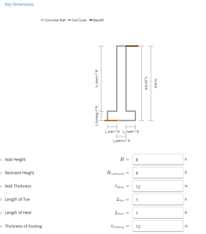
2
Soil and Load Properties
In Calcs.com, you can set a dead load or live load surcharge to be applied on the backfill.For example, a concrete slab can be modeled as a dead load surcharge. If the weight of the surcharge prevents overturning and sliding action, a dead load can be placed directly above the heel.The soil properties allow you to define the geometry of the soil, where the height of the backfill is flat with no slope, measured between the retained soil surface and the underside of the retaining wall base. The depth of the soil cover to the bottom of the footing can be set if the soil rises on top of the toe.You can also define which lateral pressure method will be used. Calcs.com supports Equivalent Fluid Pressure, Rankine and Coulomb methods.From this, the base soil properties will be calculated, including the friction coefficient and the cohesion.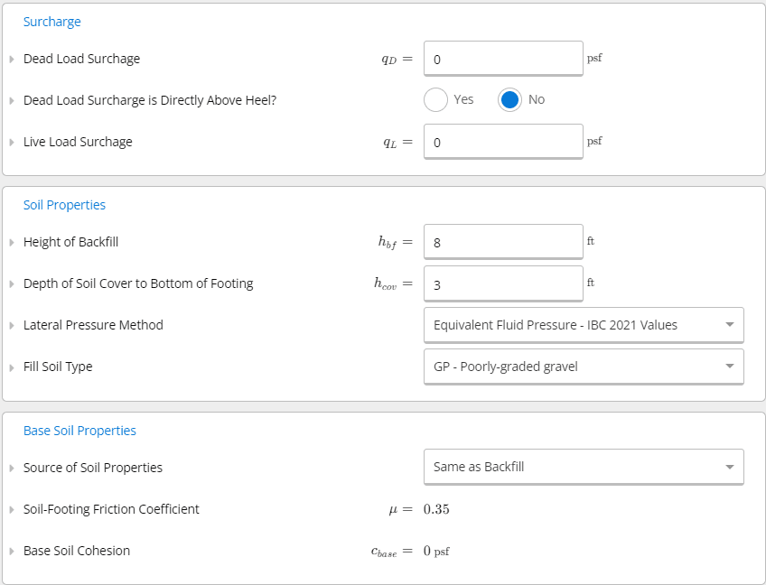
3
Concrete Properties and Reinforcement
Next, you can design the concrete and reinforcement for your retaining wall, specifying the size and location.For this calculator, the concrete detailing needs to be checked separately. Our calculations will only be used to determine if the moment and shear capacity of the stem, and heel are adequate.For the stem reinforcement, the placement can be defined with one row at the exposed face, one row at the center, or two rows at each face. This should be selected accordingly to handle negative moments, due to the restrained wall. The inputs for reinforcement are checked against ACI 318-19.Shrinkage/temperature reinforcement can also be specified as a single row of reinforcement bars running perpendicular to the wall direction.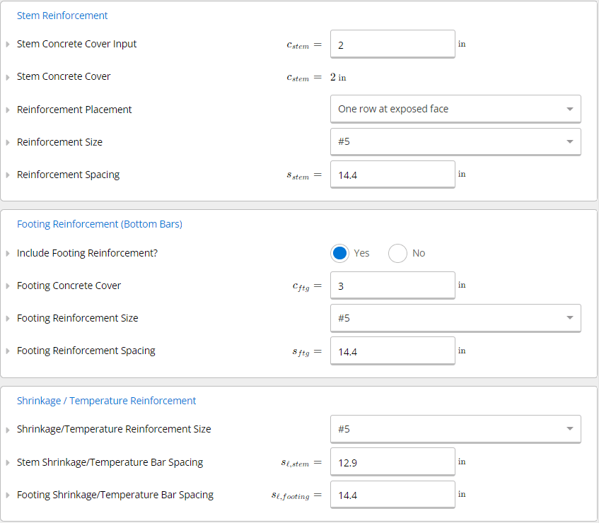
4
Summary
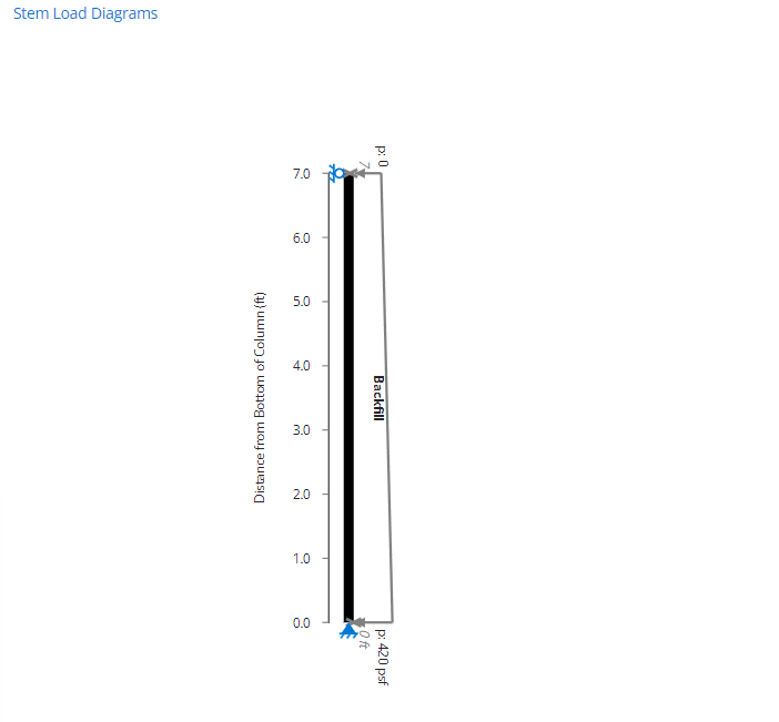
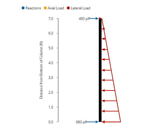
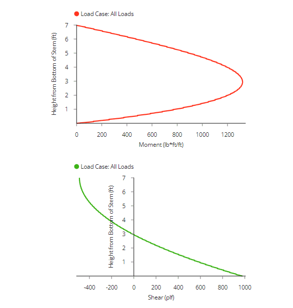
The overall stability of the retaining wall is calculated, focusing on total sliding forces and soil bearing capacity. These are compared against the minimum sliding factor of safety which can be user defined in the design criteria. The lateral force transmitted is also calculated in order to determine the reactions at both of the footing restraints. This can be seen in the stem load diagrams for the loads, moment, shear and reaction diagrams in the dropdown.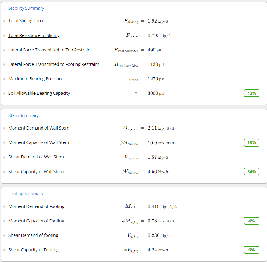
Common questions
What design standards does this calculator use?
What design standards does this calculator use?
The calculator references IBC 2024 for load combinations, ASCE 7-22 for load factors and lateral earth pressure classification, and ACI 318-19 for reinforced concrete section design. Lateral earth pressure is calculated using Rankine theory with at-rest or active soil assumptions entered by the engineer.
What are the key inputs?
What are the key inputs?
Key inputs are wall height, restraint height (distance from footing to the top restraint), wall thickness, concrete compressive strength (f’c), reinforcement bar size and spacing, concrete cover, soil unit weight, internal friction angle (phi), dead and live surcharge loads, axial dead and live loads at the wall top, and allowable bearing capacity. At-rest or active pressure is selected by the engineer.
What does the calculator check and output?
What does the calculator check and output?
The calculator checks stability (sliding, bearing), stem flexural design under combined axial load and bending moment per ACI 318-19, stem shear capacity, axial capacity of the wall stem, footing flexural and shear design, and optional shear key capacity. Utilization ratios, load demands, and lateral force diagrams are reported for both the top restraint and footing restraint.
When should I use at-rest pressure instead of active pressure?
When should I use at-rest pressure instead of active pressure?
Use at-rest earth pressure (K_0 = 1, sin(phi)) for restrained walls that cannot deflect, the typical condition for basement walls braced by a floor slab or foundation. Active pressure (K_a) applies when the top of the wall is free to translate. Most basement wall designs should use at-rest conditions.
How does this IBC 2024 version differ from the IBC 2021 version?
How does this IBC 2024 version differ from the IBC 2021 version?
The IBC 2024 version updates load combinations to IBC 2024 and ASCE 7-22 (from IBC 2021 and ASCE 7-16), adds combined axial-flexural stem design with explicit dead and live load inputs at the wall top, adds a shear key option, and includes axial capacity checks for the stem. For projects already designed under IBC 2021, use the IBC 2021 version.
What limitations apply to this calculator?
What limitations apply to this calculator?
This calculator assumes no soil inclination at grade and excludes wind and seismic lateral loads, these must be verified separately. It covers restrained (propped) configurations only. For freestanding cantilever walls, use the Cantilever Retaining Wall (IBC 2024) calculator. Expansive soils are not modeled.
Next steps
Cantilever Retaining Wall Overview
Design concrete or CMU cantilever retaining walls to IBC 2024, ASCE 7-22, ACI 318-19 and TMS 402-22, with shear key design and seismic loads.
Design a Wall Footing to ACI 318-19
Design continuous wall footings to ACI 318-19 per IBC 2021 or IBC 2024. Results cover ultimate load, bearing capacity and serviceability.
Design a Restrained (Basement) Retaining Wall
Design restrained (basement) retaining walls to IBC 2024, ASCE 7-22 and ACI 318-19, with at-rest or active soil pressure and an optional shear key.