Video Overview
Watch this video for an overview of the Steel Base Plate calculator and learn how to efficiently design steel base plates and anchor rods:
The Calcs.com Steel Base Plate calculator enables a fast and efficient design of steel base plates and anchor rods using LRFD (Load and Resistance Factor Design) methodology. The calculator provides the required base plate thickness and anchor capacities based on compressive axial capacity, flexural design, and anchor design. This calculator follows ACI 318-19, which exclusively uses Strength Design for concrete anchorage.
This calculator performs calculations per ACI 318-19, AISC 360-16, and the AISC Design Guide 1, 2nd Edition.
Want to learn more? Check out our Steel Base Plate Design webinar for an in-depth walkthrough of base plate design, including design considerations, failure modes, and worked examples using this calculator.
Assumptions and Limitations
- The base plate is assumed to be rigid and resting in the center of the concrete pier.
- Group effects for tensile and shear are limited to the grouped anchors on one side of a plate.
- Cases where net tension is applied to the base plate are not currently supported.
Inputting Data
Key Properties
Begin by defining the geometry and material properties of your column and base plate.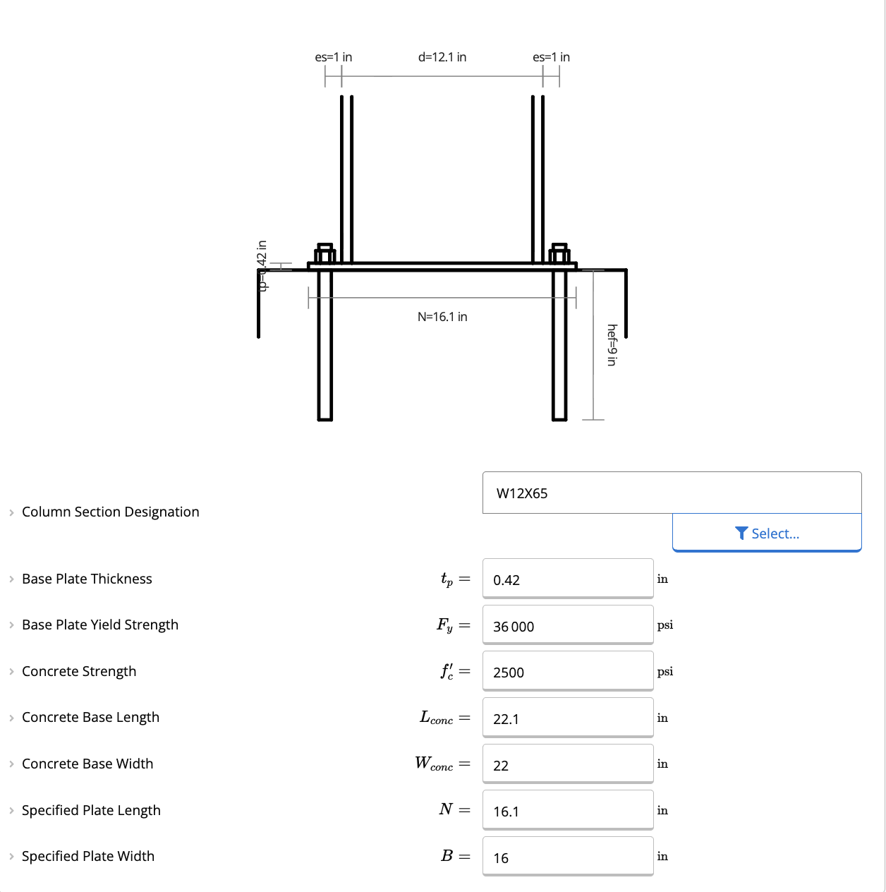
- Column Section Designation: Select your column size from the database (W, S, M, HP, HSS, HSS-R, or PIPE sections).
- Base Plate Dimensions:
- Thickness (): Enter your desired thickness. The calculator will check this against the required minimum thickness ().
- Yield Strength (): Typically 36 ksi (A36 steel), but can be adjusted.
- Plate Length () & Width (): Define the physical dimensions of the plate.
Anchor Rod Properties
Configure the anchorage for the connection.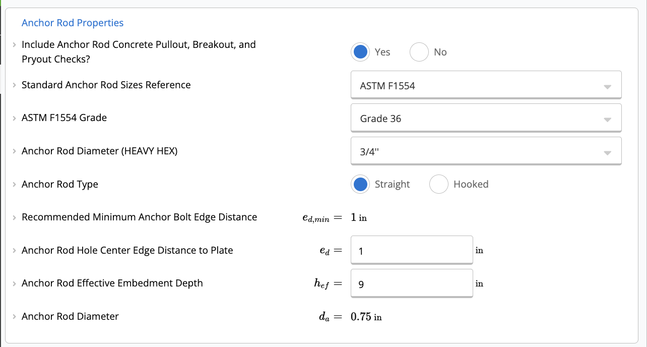
- Standard Reference: Choose between ASTM F1554 grades (Grade 36, 55, 105) or Custom anchor rods.
- Rod Diameter (): Select a standard diameter (e.g., 3/4”) or enter a custom value.
- Anchor Type: Choose between Straight or Hooked rods.
- Embedment (): Define the effective embedment depth.
- Edge Distance (): Specify the distance from the center of the anchor to the edge of the plate.
The calculator currently defaults to a 4-bolt configuration.
Concrete Properties
Define the supporting concrete pedestal or foundation.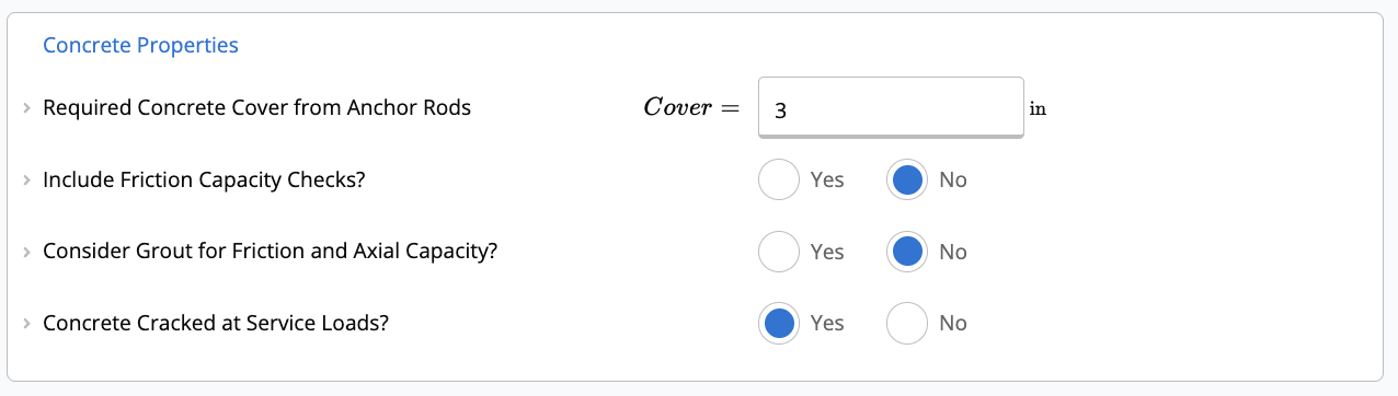
- Concrete Strength (): Compressive strength of the concrete (e.g., 3000 psi).
- Base Dimensions: Enter the length () and width () of the concrete support.
- Grout: You can toggle whether to include a grout pad and specify its strength ().
- Cracked Concrete: Specify if the concrete is assumed to be cracked at service loads (affects anchor breakout capacity).
Applied Loads
Input your unfactored loads. The calculator will automatically apply load combinations based on ASCE 7-16 (or your project defaults).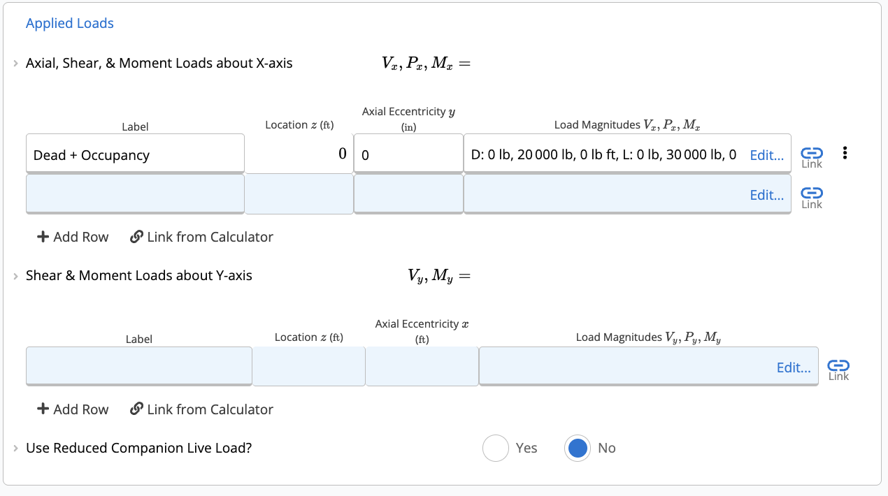
- Axial, Shear, & Moment (X-Axis): Enter loads acting about the X-axis (Strong axis).
- Shear & Moment (Y-Axis): Enter loads acting about the Y-axis (Weak axis).
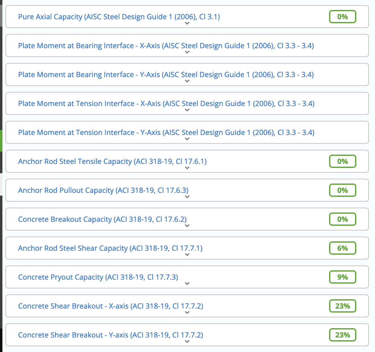
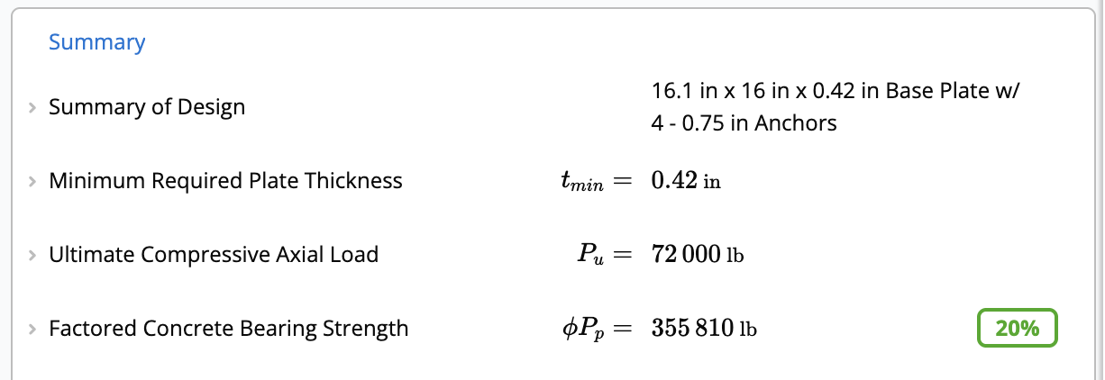
Understanding the Results
The calculator provides real-time checks for various failure modes.Summary
- Minimum Required Plate Thickness (): The governing thickness required to satisfy bending demands from axial and moment loads.
- Concrete Bearing Strength (): Checks if the concrete/grout can support the compressive loads.
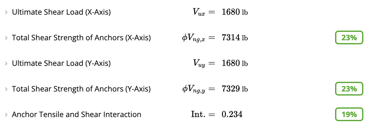
Anchor Capacity
If Include Anchor Rod Concrete Pullout, Breakout, and Pryout Checks? is set to Yes, the following are checked using factored (LRFD) loads:- Total Tensile Capacity of Anchors: Checks steel strength, concrete breakout, and side-face blowout.
- Total Shear Strength of Anchors: Checks steel shear strength, concrete breakout, and pryout strength in both X and Y directions.
- Anchor Tensile and Shear Interaction: Checks combined tension and shear interaction (must be ).
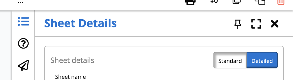
Detailed Checks
Want to dig deeper? Scroll down to the detailed sections to see exactly how each capacity is calculated.Pro Tip: Ensure your view is set to “Detailed” using the toggle at the top of the calculator. This reveals all intermediate steps and formulas used in the calculations.
- Plate Bending (): Verifies the plate’s capacity against the ultimate moment demand at the bearing interface.
- Concrete Breakout (): Reviews the projected failure areas and specific modification factors () used for edge distance, eccentricity, and cracking.
- Frictional Shear (): If enabled, calculates the shear capacity provided by friction between the base plate and concrete.