

All regions

Perform lightning fast analysis of any arbitrary cross-section. Default options make it easy to input the geometry for I-section, T-sections, angles, Cees, Zeds, and more. Analysis outputs include everything from second moments of area to section moduli to warping and torsion constants. Within the Calcs.com platform, arbitrary cross-sections can be linked in to design calculators to use your custom cross-section in a design.
The Calcs.com cross-section calculator allows the user to input the geometry of an arbitrary cross-section using either simple dimensions of common shapes or fully-custom outline definitions. It then determines the elastic, warping, and/or plastic properties of that section - including areas, centroid coordinates, second moments of area/moments of inertia, section moduli, principal axes, torsion constant, and more!
You can use the cross-section properties from this tool in our beam analysis and portal frame calculators.
Method & scope
Calculation method
The Custom Cross-Section Properties calculator uses numerical mesh analysis to compute the full set of section properties for any arbitrary planar cross-section. You define the geometry using parametric shape primitives or a free-form polygon, and the calculator assembles the section, meshes it, and solves for properties that range from simple area integrals through to the torsion and warping problems that require a boundary-value solver.Geometry input and composite sections
The calculator provides a library of built-in section types to cover the most common fabricated shapes:- I-section and T-section, depth, flange width, flange thickness, web thickness
- Angle section, leg lengths and thickness
- Channel (C and Z sections), height, flange width, thickness
- Rectangular and hollow rectangular, width, depth, and optional wall thickness
- Circular and hollow circular, outer diameter and optional wall thickness
- Custom polygon, vertex coordinates for fully arbitrary outlines
Area properties from direct integration
For simple geometry, first-order and second-order area properties are computed directly from the section outline by integration:- Gross area: A = integral of dA over the section
- Centroid: x̄ = (integral of x dA) / A, ȳ = (integral of y dA) / A
- Second moments of area: Ixx and Iyy about centroidal axes
- Product moment of area: Ixy (non-zero for asymmetric sections such as angles and Z-sections)
- Principal axes: rotation angle theta_p where Ixy = 0, and principal second moments I1, I2
- Section moduli: Zx = Ixx / y_max, Zy = Iyy / x_max (elastic)
- Plastic section moduli: Sx and Sy, computed by locating the plastic neutral axis where equal areas lie above and below
- Radii of gyration: rx = sqrt(Ixx / A), ry = sqrt(Iyy / A)
Shear center
The shear center is the point through which a transverse shear force produces bending without twist. For doubly-symmetric sections it coincides with the centroid; for asymmetric open sections (angles, channels, Z-sections) it lies off the centroid and must be computed from the shear flow distribution. The calculator solves the shear flow problem using the thin-wall approximation for standard section shapes and the full finite element solution for arbitrary polygons. The shear center coordinates (x_s, y_s) are reported relative to the centroid.Torsion constant (J)
The St Venant torsion constant J resists uniform torsion. For closed (hollow) sections it is computed from the Bredt formula: J = 4 A_enclosed² / integral(ds / t) where A_enclosed is the enclosed area and t is the wall thickness at each point along the perimeter. For open sections, the thin-wall approximation gives: J ≈ (1/3) sum(b_i × t_i³) where each segment i has breadth b_i and thickness t_i. For irregular sections, the full Saint-Venant torsion boundary-value problem is solved on the mesh, giving the result T = G J (d theta / dz). The mesh-based result is more accurate than the thin-wall approximation for stocky flanges or re-entrant corners.Warping constant (Cw)
The warping constant Cw (also written as Iw) governs non-uniform torsion and lateral-torsional buckling calculations. It is defined by: Cw = integral of omega² dA where omega is the normalized warping function at each point of the cross-section. The calculator solves the warping problem on the mesh to determine the warping function distribution, then integrates to get Cw. For doubly-symmetric I-sections the closed form is: Cw = (Iy × h_0²) / 4 where h_0 is the distance between flange centroids. The mesh solution matches this for standard shapes and extends to arbitrary geometry where no closed-form exists.Mesh and accuracy
The cross-section is divided into triangular elements. The calculator displays the mesh in the diagram output so you can verify that the geometry has been interpreted correctly before accepting results. More complex shapes with re-entrant corners or thin outstanding elements are handled by automatic mesh refinement where aspect ratios would otherwise degrade accuracy. Three assumptions apply to all results:- Entered dimensions must be physically realizable, no overlapping sub-areas within the same region
- No new enclosed areas are created by stacking shapes (each enclosed void must be explicitly modeled as a hollow)
- Properties are for the gross unreduced section, effective section properties for slender elements under compression require a separate reduction per the applicable design code
How to use it
1
Linking a custom cross-section into beam & column design calculators
The typical workflow for using a non-catalog section in a design calculation is:
- Create a Custom Cross-Section Properties calculation to define the geometry and compute properties.
- Link it into a beam or column design calculator (e.g. AISC Steel Beam, AS 4100 Steel Beam, Wood Column) as the section.
- Check standard database sections individually: often a single catalog section covers the demand once bracing and load path are set correctly.
- Use a single custom I-section that conservatively bounds the built-up shape.
- Use the Custom Cross-Section calculator for properties only, and perform the code check by hand against those properties. You can request additional section types via the section request process.
- ‘Key Properties’, where the geometry of the cross-section is defined.
- ‘Summary’, where the type of analysis is selected and the calculated properties are displayed.
2
Key Properties
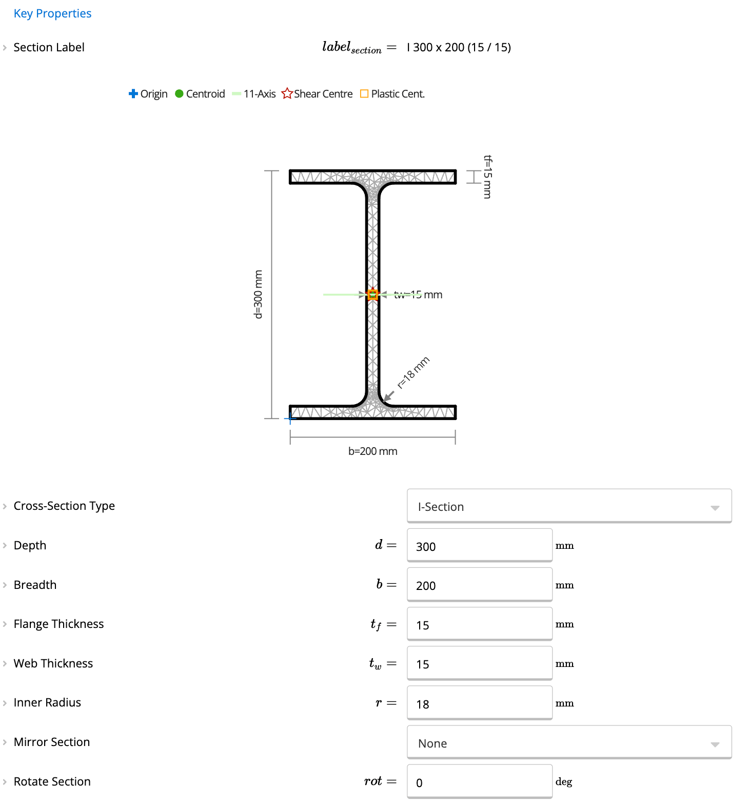
- Primary Section:
- The primary section is the section you define at the start of the calculator. Use the dropdown menus and input fields to specify its type, dimensions, and properties.
- Enable Composite Section:
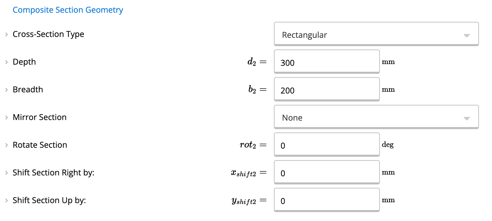
- In the Key Properties section, select “Yes” for the Composite option. This unlocks additional input fields to define a secondary section.
- Add a Secondary Section:
- After enabling the composite option:
- Specify the Secondary Section Type from the dropdown (e.g., rectangular, circular, I-section).
- Enter the required dimensions and offsets for the secondary section.
- Use the Shift and Rotation fields to position the secondary section relative to the primary section
- After enabling the composite option:
- Visualize the Composite Section:
3
Summary Outputs and Analysis Types
Five different Analysis Type options are available: “None”, “Elastic Only”, “Elastic + Warping”, “Elastic + Plastic”, and “Full”. The default, and fastest, option is “Elastic Only”, while the other options add warping and/or plastic analyses as well. Note that an elastic analysis is always performed in every option.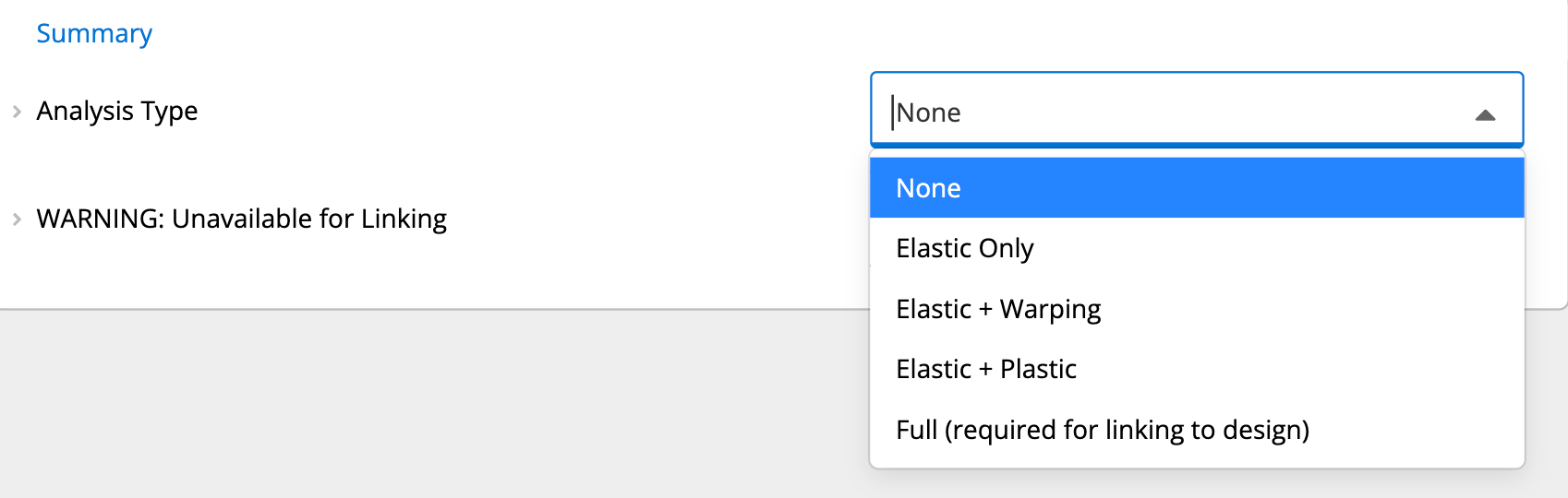
- Angle of Major Principal Axis: The major principal axis (the “1” axis) may be inclined to non-symmetric sections, or it may be at 90 degrees if the section has more lateral than vertical stiffness. This defines its angle, relative to the X-axis. Note that the minor principal axis (the “2” axis) is exactly perpendicular to this. The principal axis orientation is also indicated on the cross-section diagram.
- Area: The cross-sectional area of the section. This value is commonly used in determining the axial strength of a column.
- First Moments of Area: The first moments of area are relevant for certain shear calculations, such as shear flow. Note that the first moments are areas taken about the centroid and the geometric axes.
- Second Moments of Area / Moments of Inertia: The second moments of area, also known in engineering as the moments of inertia, are related to the bending strength and deflection of a beam. Note that all values are taken about the centroid of the cross-section, though values are available for both geometric and principal axes. The Polar Moment of Inertia is identical for both types of axes, as the “Z” axis is always assumed to be the same as the “3” axis. The Product Moment of Inertia is, by definition, zero for principal axes.
- Elastic Section Moduli: The elastic section moduli are equal to the second moments of area/moments of inertia divided by the distance to the farthest fiber in the cross-section perpendicular to the axis of bending. Values are provided for both positive and negative bending, where positive bending is defined as the top-most or left-most portion of the cross-section being in compression. Values are also provided for both geometric and principal axes and are always about the centroid. N.B. Elastic section modulus is also known as statical section modulus.
- Distance from Centroid to Extreme Fibers: The distance between the centroid of the cross-section and the extreme fiber of the cross-section, perpendicular to the axis of bending. The second moments of area/moments of inertia divided by these distances will equal the elastic section moduli.
- Radii of Gyration: The radii of gyration are the root mean square distances of each fiber in the cross-section relative to the given axis. Values are always about the centroid and are available about both the geometric and principal axes. The Polar Radius of Gyration is identical for both types of axes, as the “Z” axis is always assumed to be the same as the “3” axis.
- Centroid: The location of the centroid is shown in the cross-section diagram. Mouse over the green circle icon and a tooltip will display the exact coordinates of the centroid. Note that the origin (0,0) location is indicated by blue crosshairs.
- St Venant Torsion Constant: The torsion constant is related to how well the cross-section can resist pure torsional forces and is commonly used in lateral-torsional buckling formulae.
- Warping Constant: As a torsional or eccentric force is applied, the cross-section may not just twist but also warp. This constant is a measure of how easily that warping can happen and is often used in lateral-torsional buckling formulae.
- Shear Areas: Only some of a cross-section will effectively resist a shear force applied about a given axis (that is, a shear force perpendicular to the given axis). The values shown are based upon a shear flow integration, and as such, they may not exactly match classical calculations based upon areas of a web.
- Monosymmetric Constants: The monosymmetry constants define how close a cross-section is to be symmetric. The constant approaches zero when a cross-section is symmetric about the given axis.
- Shear Center: The location of the shear center is shown in the cross-section diagram. Mouse over the star icon and a tooltip will display the exact coordinates of the shear center. Note that the origin (0,0) location is indicated by blue crosshairs.
- Plastic Section Moduli: The plastic section moduli are shown for both geometric and principal axes. Note that while the plastic section modulus is not dependent upon the direction of bending, the shape factor, which is the ratio of plastic to elastic section moduli, is so dependent.
- Plastic Centroid: The location of the plastic centroid is shown in the cross-section diagram. Mouse over the orange square icon and a tooltip will display the exact coordinates of the plastic centroid. Note that the origin (0,0) location is indicated by blue crosshairs.
Custom Cross-Sections: Overview
Custom Cross-Sections: Example
Custom Thin Wall Section Properties Calculator Overview
Available presets
Each preset opens the calculator with a typical setup already entered.Common questions
What is moment of inertia (second moment of area)?
What is moment of inertia (second moment of area)?
The moment of inertia (also called the second moment of area) measures how a cross section resists bending about a given axis. A higher I value means the section is stiffer in bending. It appears in the beam bending formula M = EI × d²y/dx² and is the fundamental input for deflection and stress calculations.
What properties are included for each section?
What properties are included for each section?
For each section you get: cross-sectional area (A), second moment of area (I_x, I_y), elastic section moduli (S_x, S_y), plastic section moduli (Z_x, Z_y), radius of gyration (r_x, r_y), torsion constant (J), warping constant (I_w), shear areas (A_vx, A_vy), centroid location, shear center, and self-weight. Material properties, yield strength F_y, elastic modulus E, shear modulus G, and characteristic timber strengths, are also included. Cold-formed steel sections include DSM buckling factors.
What design code does this calculator use?
What design code does this calculator use?
This is a pure geometry analysis calculator, it does not reference a design code. It computes cross-section properties (area, centroid, second moments of area, section moduli, shear center, warping constant, torsion constant) from the geometry you enter, independent of any material or building standard. Those properties then feed into code-specific design calculators for AS 4100, AISC 360, EN 1993, or any other standard.
What are the key inputs?
What are the key inputs?
You choose a section type from the built-in geometry library (I-section, T-section, angle, channel, rectangular hollow, circular, or fully custom polygonal shape) and enter the corresponding dimensions, depths, widths, flange and web thicknesses. For composite sections, you add a second shape and set its position offset. For the full analysis mode you can also include steel database members (Australian, US, or European standard sections) as one component of a composite section.
What properties does it calculate?
What properties does it calculate?
Standard outputs include gross cross-sectional area (A), centroid location, second moments of area about both principal axes (Ixx, Iyy), product moment of area (Ixy), section moduli (Zx, Zy), radii of gyration (rx, ry), plastic section moduli (Sx, Sy), and shear center location. The full analysis mode adds St Venant torsion constant (J) and warping constant (Cw), which are required for lateral-torsional buckling and torsion design checks.
Can I use a custom cross-section in a beam or column design calculator?
Can I use a custom cross-section in a beam or column design calculator?
Yes, that is the primary use case. Within a Calcs.com project, the calculated section properties from this calculator link directly into steel beam, steel column, or timber design calculators. When you change a dimension in the cross-section calculator, every linked design calculation updates automatically. This is how engineers model fabricated plate girders, castellated beams, or built-up sections that do not appear in the standard section libraries.
How accurate is the mesh-based analysis for torsion and warping constants?
How accurate is the mesh-based analysis for torsion and warping constants?
The calculator meshes the cross-section geometry and solves the torsion and warping problems numerically. Accuracy depends on mesh refinement, finer meshes give results closer to closed-form values. The calculator displays the mesh in the diagram so you can inspect it before accepting results. For simple shapes (solid rectangle, circle, thin-walled open sections) results match published handbook values to within numerical precision. For irregular shapes, the mesh solution is the only practical approach and results are suitable for structural design purposes.
Next steps
Design a PFC and Angle Section to AS4100-1998
Design combined PFC and angle steel sections to AS 4100:1998. Checks bending capacity, deflection, and brick-load stress on the angle leg.
Design a PFC and Plate Section to AS4100-1998
Design combined PFC and plate steel sections for masonry support to AS 4100:1998. Checks bending capacity, short- and long-term deflection, and plate stress.
Use the Custom Thin-Walled Section Properties Calculator
Run rapid buckling analysis of any thin-walled cross-section. A CUFSM port returns critical buckling parameters Mol, Mod, and Mo for the Direct Strength Method.
Create and Use a Custom Section in the Custom Truss Analysis
Learn how to build a custom truss layout, define member types, create a custom cross-section, and link it into the Custom Truss Analysis calculator.