

All regions
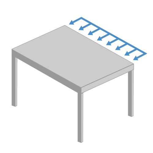
Perform FEA-based analysis of simple flexible diaphragms with unlimited loads and braced wall lines. Results include governing shear demand and per-wall-line load distribution for wind and seismic. Available on the free plan.
Method & scope
Scope: simple flexible diaphragms without torsion
The Diaphragm Analysis calculator models a simple flexible diaphragm without torsion, essentially a 1D load path between braced wall lines. You define the diaphragm length and the braced walls that support it; the calculator distributes lateral load to those walls. It is not a general 2D diaphragm model. Systems that need torsion, irregular plan geometry, or open/cantilevered layouts should be analyzed with another method outside this calculator.Calculation method
The Diaphragm Analysis calculator models a flexible diaphragm as a one-dimensional beam spanning between braced wall lines, using an FEA beam solver to distribute lateral wind and seismic demands.Flexible diaphragm assumption
The calculator assumes a fully flexible diaphragm. Under this assumption, lateral loads are distributed to each vertical resisting element (braced wall line) by tributary area only, each span between adjacent wall lines is treated as an independent simple beam. This is the approach required by ASCE 7 and IBC for wood-sheathed diaphragms that meet the flexible diaphragm classification criteria. To model this correctly, the calculator inserts a hinge immediately adjacent to each interior braced wall line. The exterior wall lines are pinned supports. The result is that each span resolves independently with no moment transfer between spans.Load input and load cases
Line loads are entered as distributed lateral forces with a start position and end position along the diaphragm. Each load entry specifies separate magnitudes for two load types:- (W) Wind: lateral wind load on the diaphragm
- (E) Seismic: lateral seismic load on the diaphragm
FEA solver and shear distribution
The FEA beam solver processes all load combinations simultaneously and returns the following for each load case:- Reaction at each braced wall line (R_w for wind, R_E for seismic)
- Shear diagram along the diaphragm length
- Governing shear demand V, the maximum in-plane shear at any cross-section
Demands table
The demands table collects the per-wall-line reactions from the FEA results and presents wind load and seismic load for each named braced wall line. These values feed directly into shear wall and diaphragm nailing design. V_governing = max(V_wind, V_seismic)How to use it
1
Linking wind loads: MWFRS Envelope Procedure is required
To link wind pressures into the Diaphragm Analysis calculator:
- Open your Wind Loads calculation.
- Set Calculation Type to MWFRS (Envelope Procedure). Do this before linking; switching after the fact will not backfill the linked values.
- Return to the Diaphragm Analysis calculator and link the wind load from the Envelope Procedure Wind Loads sheet.
Common questions
What is a diaphragm in structural engineering?
What is a diaphragm in structural engineering?
A diaphragm is a horizontal structural element (floor or roof) that transfers lateral loads (wind or seismic) to the vertical resisting system (shear walls or braced frames). It acts like a horizontal beam spanning between braced wall lines.
How do I enter wind loads?
How do I enter wind loads?
Enter the total lateral force or a uniform wind pressure along the diaphragm span. For ASCE 7 wind loads, compute the design wind pressure and enter the resulting tributary load per unit length.
What is the difference between shear walls and portal frames in this context?
What is the difference between shear walls and portal frames in this context?
Both are vertical resisting elements. The calculator treats them identically, they are simply lateral force resisting elements at specified positions. The distinction matters for capacity design but not for the force distribution this calculator performs.
What analysis method does this calculator use?
What analysis method does this calculator use?
The calculator uses a FEA beam solver to model the diaphragm as a simple flexible beam spanning between braced wall line supports. For flexible diaphragms, loads are distributed to vertical resisting elements by tributary area only, each span between adjacent wall lines is treated as an independent simple beam. This is consistent with the flexible diaphragm assumption in IBC and ASCE 7 for wood-sheathed diaphragms.
What are the key inputs?
What are the key inputs?
Key inputs are the diaphragm length (perpendicular to the loading direction), the positions of each braced wall line measured from the left end, and the lateral loads applied as distributed line loads. Each load entry requires a start location, end location, and magnitude for wind (W) and seismic (E) load types independently.
What does the calculator output?
What does the calculator output?
The calculator reports the governing shear demand in the diaphragm (maximum in-plane shear), the governing load type (wind or seismic), and a demands table showing the total wind and seismic load carried by each braced wall line. Diagrams show the shear distribution, free body diagram, and reaction summary for the selected load case.
Can I model a diaphragm with more than two wall lines?
Can I model a diaphragm with more than two wall lines?
Yes. Any number of intermediate braced wall lines can be added. Each interior wall line gets a hinge inserted adjacent to it so that each span is treated as a simple beam, consistent with flexible diaphragm tributary area assumptions. The minimum configuration is two wall lines (at each end).
Does this calculator handle torsion or rigid diaphragms?
Does this calculator handle torsion or rigid diaphragms?
No. Only simple flexible diaphragms without torsion are supported. Loads must act perpendicular to the diaphragm span direction. For buildings where the diaphragm cannot be classified as flexible, a rigid or semi-rigid analysis is required and is outside the scope of this calculator.
Is this the free version? What is different from the full Diaphragm Analysis calculator?
Is this the free version? What is different from the full Diaphragm Analysis calculator?
Yes, this is the free-plan version. It provides full FEA-based flexible diaphragm analysis with unlimited wall lines and loads. The free version is available without a paid subscription, making it a practical tool for quick checks or for engineers who are evaluating the platform.
Next steps
Use the Diaphragm Analysis (Load Linking) Calculator
Analyze flexible diaphragms with FEA and unlimited loads and wall lines. Load distribution and in-plane shear, with wall-line reactions linked to shear walls.
Use the Beam Analysis Calculator
Get bending moment, shear force and deflection along single or multi-span beams using linear-elastic FEA. Handles cantilevers, continuous spans and mixed loads.
Use the Truss Analysis Wizard
Solve 2D roof, floor and custom trusses with a live FEA engine. Set nodes, fixities and members in the browser and see results as you work.