

United States

Post and column loads link directly from the calculations above, so changes propagate to the footing automatically. Design pier, pole, and deck-post footings to ACI 318-19 per IBC 2024. Results cover lateral embedment, vertical bearing, compression-bending interaction, shear, and uplift with skin friction resistance below the active soil zone.
See how to design a Deck Pier Footing using Calcs.com’s Pier Footing calculator.
Download this example as a PDF: Deck Pier Footing [USA Pier Footing]
This design example is part 4 of 4 in our “Deck Design Series.” For more information on how to use Calcs.com to design a deck, click here.
Please be aware that this example should not be used as advice, recommendations, or instructions for engineering design and should only be followed as a guide to using Calcs.com.
Method & scope
Calculation method
The Pole Footing (IBC 2024) calculator designs plain (unreinforced) concrete pier, pole, and deck-post footings to ACI 318-19 under IBC 2024, with ASD and LRFD load combinations from ASCE 7-22 (Ch. 2). The pier is assumed to be continuously restrained against buckling by the surrounding soil, so unbraced-length effects are neglected in the concrete compression checks.Lateral embedment (IBC 2024, Cl. 1807.3)
The governing check for pole footings is the embedment depth needed to resist lateral load without excessive rotation. The IBC 2024 method evaluates the lateral soil-bearing pressure at one-third of the embedment depth and at the full depth:- S_(1/3), lateral soil stress at one-third of the embedment depth
- S_d, lateral soil stress at the full embedment depth
Vertical bearing
Gross vertical bearing pressure is the total downward service load divided by the pier base area: utilization = q_gross / q_a ≤ 1.0Compression and bending capacity (ACI 318-19, Ch. 21)
The pier is checked as a plain concrete member under combined axial load and moment. Nominal moment capacity is evaluated on the tension and compression faces and combined with the compression capacity: utilization = (P_u / (phi × P_n)) + (M_u / (phi × M_n)) ≤ 1.0 with phi = 0.60 for plain concrete in combined loading.Shear capacity (ACI 318-19, Ch. 21)
One-way shear demand is compared to the plain-concrete shear strength: utilization = V_u / (phi × V_c) ≤ 1.0Uplift and downward safety factors
Uplift from wind or seismic is resisted by self-weight plus skin friction below the active soil movement zone: FS_uplift = (W_pier + W_soil + f_s × A_skin) / T_net ≥ FS_min A downward capacity check confirms the pier and bearing soil carry the maximum compressive service load: FS_down = R_down / P_max ≥ FS_min The active (movement) zone depth is a user input, so skin friction acts only below it. The wall or post self-weight above is not counted in the uplift resistance.Concrete bearing at the post interface (ACI 318-19, Cl. 22.8)
Bearing stress where the post or bracket lands on the pier is compared to the plain-concrete bearing capacity. This check governs when concentrated loads transfer from a steel post base or bracket into the top of the pier.Assumptions
The post is centered on a prismatic pier and designed separately. The footing is unreinforced (plain) concrete. Per IBC 2024 Cl. 1807.3, embedded posts are not used to provide lateral support for materials such as plaster, masonry, or concrete unless separate bracing is provided. Pier deflection and movement, where applicable, are checked separately.How to use it
1
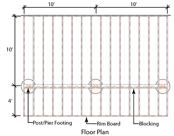
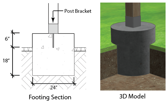
Diagram
2
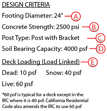
Design Information
3
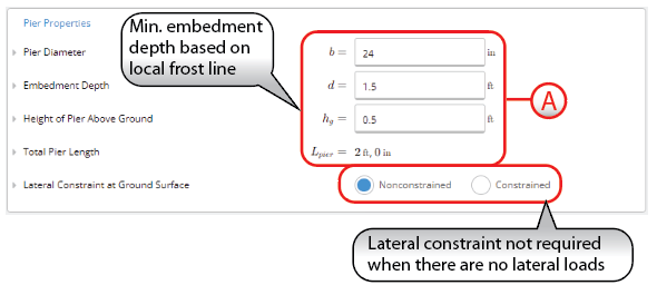
Pier Properties
4
Concrete Properties
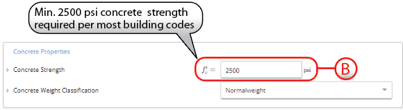
5
Post Properties
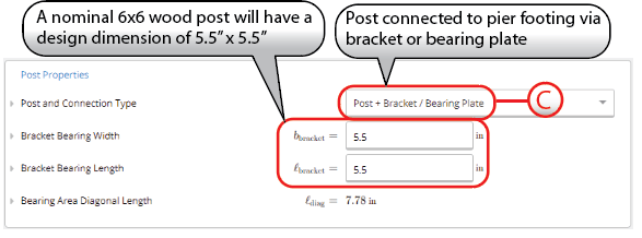
6
Soil Properties
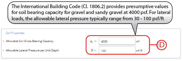
7
Loads
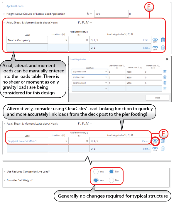
US Pier Footing: Overview
US Pier Footing: Example
Resistance checks against uplift and downward forces in pier footing designs
Common questions
What design standards does this calculator use?
What design standards does this calculator use?
The calculator uses IBC 2024 Cl. 1807.3 for lateral embedment, ACI 318-19 Chapter 21 for plain-concrete compression, bending, shear, and bearing capacity, and ASCE 7-22 (Ch. 2) for ASD and LRFD load combinations. This is the current edition for 2024 IBC projects.
What are the key inputs?
What are the key inputs?
Key inputs are pier diameter, embedment depth, and height above ground, concrete strength and density, the post type and dimensions (round or rectangular post, or steel bracket bearing width and length), allowable gross soil bearing capacity, allowable lateral soil pressure per unit depth, allowable uplift and downward skin friction values, length of the active (movement) soil zone, and the height at which lateral load is applied. Applied vertical and lateral loads can be entered manually or linked from a post or column calculation above.
What does the calculator check and output?
What does the calculator check and output?
It checks lateral embedment (the required versus provided depth), vertical bearing pressure, combined compression and bending capacity of the plain-concrete pier, one-way shear, concrete bearing at the post interface, and uplift and downward safety factors including skin friction below the active soil zone. Demand, capacity, and utilization are reported for each check.
Can I use it for deck posts, poles, and bracket-mounted columns?
Can I use it for deck posts, poles, and bracket-mounted columns?
Yes. The calculator suits residential and light-commercial pier, pole, and deck-post footings. Choose a round or rectangular embedded post, or a steel post landing on a bracket, and enter the base reaction (often from a deck-beam calculation above). Concentric loads set the lateral load to zero; lateral wind or seismic loads drive the embedment check.
How is the embedment depth determined, and what does the active soil zone do?
How is the embedment depth determined, and what does the active soil zone do?
Embedment follows IBC 2024 Cl. 1807.3, comparing the lateral soil-bearing pressure at one-third of the depth and at full depth against the allowable. Nonconstrained posts (free at grade) need a deeper embedment solved from moment equilibrium; a constrained post (braced at grade) can be shorter. The active (movement) zone depth is a separate input, and uplift skin friction is credited only below it, relevant on expansive or frost-susceptible soils.
Does this calculator support load linking with column or post calculations?
Does this calculator support load linking with column or post calculations?
Yes. If a column, post, or deck-beam calculation sits above the footing in the same Calcs.com project, the axial and lateral reactions at the base link directly. When the loading or member above changes, the footing automatically re-runs embedment, bearing, compression-bending, shear, and uplift with the updated reactions, no manual re-entry.
Next steps
Design a Combined Footing to ACI 318-19
Design combined rectangular footings for two columns to ACI 318-19 per IBC 2024: bearing, overturning, sliding, flexure, shear and development length.
Design a Spread Footing (IBC 2024)
Design isolated spread footings to ACI 318-19 per IBC 2024 (ASCE 7-22): bearing, flexure, one-way and punching shear, and development length.
Spread Footing to ACI 318-14 - Validation Examples
Validation and design examples for concrete spread footings to ACI 318-14.
Design a Wall Footing to ACI 318-19
Design continuous wall footings to ACI 318-19 per IBC 2021 or IBC 2024. Results cover ultimate load, bearing capacity and serviceability.