

United States

Footing loads link to the wall above, so load changes propagate downstream automatically. Design continuous wall footings to ACI 318-19 per IBC 2021 or IBC 2024. Results cover ultimate load, bearing capacity, and serviceability.
This design example shows the typical design of a reinforced concrete wall footing under concentric loads. It was originally designed and used in the following reference:
James Wight, Reinforced Concrete Mechanics and Design, 7th Edition, 2016, Pearson, Example 15-1
This is a very thorough textbook on reinforced concrete and we recommend it as a reference for concrete design in the United States.
Method & scope
Design Criteria
We will design our footing to resist its load and check it for:- Soil bearing pressure
- Shear resistance
- Flexural resistance
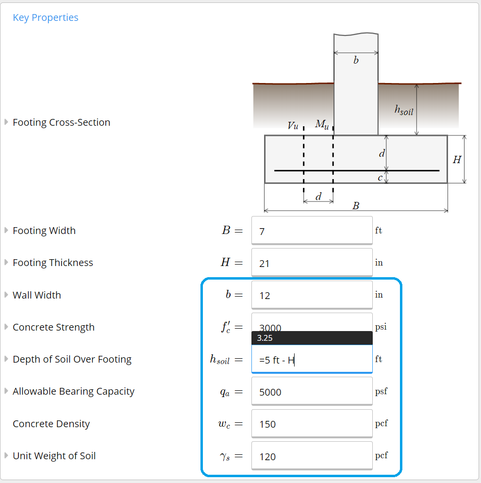 Looking at the reinforcement section, the concrete cover is already set to 3 inches (the minimum for footings) and the steel strength is already 60 ksi. All that’s left here is to find the size and spacing required.
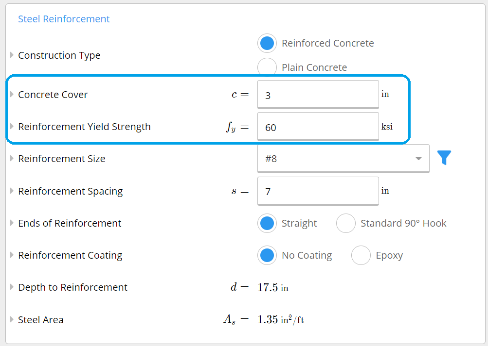 Entering our loads:
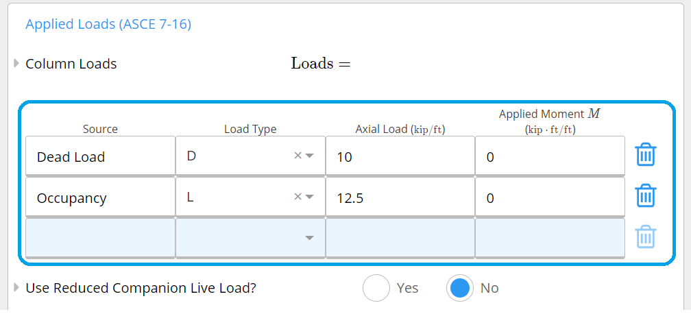 Notice that we don’t use the reduced companion live load - in this case, since we only have dead and live loads, this won’t affect the results, and since we don’t know the source of the live load it’s conservative not to reduce the live load. See ASCE 7-16, Cl 2.3.1 for more information.
Calculation method
The Wall Footing (ACI 318-19) calculator designs continuous strip footings per ACI 318-19, with load combinations from ASCE 7-16 (IBC 2021) or ASCE 7-22 (IBC 2024). It checks bearing pressure under service loads, flexural reinforcement, one-way shear, and reinforcement development length.Bearing pressure check (ASD, ASCE 7-16/22 Ch. 2)
Service loads are combined using ASD load combinations to compute the gross soil bearing stress q_s at each load case: utilization = q_s / q_a ≤ 1.0 Stability checks for sliding (FS_s), overturning (FS_ovt), and uplift are also reported under service loads.Flexural design (ACI 318-19, Cl. 22.2)
Factored moment demand M_u is calculated at the critical section (face of the wall) from the net upward soil pressure under the LRFD load combinations. Required flexural reinforcement area A_s is compared to the provided area and to the minimum reinforcement: A_s,min = 0.0018 × H × b (per ACI 318-19, Cl. 7.6.1) utilization = M_u / (phi × M_n) ≤ 1.0 Compression reinforcement is not considered in bending strength calculations.One-way shear (ACI 318-19, Cl. 22.5)
The critical shear plane is taken at distance d (effective depth) from the wall face. Shear capacity phi × V_c uses the concrete shear strength formulation per ACI 318-19: utilization = V_u / (phi × V_n) ≤ 1.0 No shear reinforcement is included.Development length (ACI 318-19, Cl. 25.4)
Available development distance is l_a = B/2, b/2, cover. Required development length l_d is calculated per ACI 318-19 and reduced for excess reinforcement area (A_s,reqd / A_s,provided). If development length is insufficient, the calculator automatically checks whether a plain concrete design is adequate.Top (negative moment) reinforcement
For cases with overturning moments generating tension at the top of the footing, top bar reinforcement is also checked for negative bending capacity and development length.Assumptions
Wall is centered on the footing. Lateral loads are only used for the sliding check. No shear reinforcement is considered. Wall reinforcement is assumed to continue directly into the footing (interface is not checked). There are no significant changes between IBC 2021 and IBC 2024 or between ASCE 7-16 and ASCE 7-22 that affect this calculation.How to use it
1
Problem Statement
Design a reinforced concrete to support a concrete wall in a relatively large building. The wall is 12 inches thick and carries unfactored dead and live loads of 10 kip/ft and 12.5 kip/ft respectively. The allowable soil pressure is 5,000 psf and the its density is of 120 pcf. The bottom of the footing should be at 5 ft below ground level. Concrete strength is 3,000 psi and reinforcement strength is 60,000 psi.
2
Soil Bearing
The first thing to do is to determine the width of our footing, which is determined by the allowable soil bearing capacity. We need to estimate the required thickness of the footing, since the self-weight of the footing is usually quite significant.The textbook recommends using a value of 1-1.5 times the wall thickness for the footing thickness. In the example, they first try with a 12 inch thick footing. Once we have this, we can calculate the self-weight:Once we know the self-weight, we immediately remove it from the allowable bearing pressure, together with the weight of the soil above the footing, and then divide the total load by this adjusted bearing pressure to find the required area.We thus select a footing width of 62 inches or 5.17 ft.Checking in Calcs.com, we can see that a 5.17 ft wide x 1 ft thick footing efficiently makes full use of the bearing capacity. However, we can already see a storm on the horizon! Our shear capacity may not be quite enough with only 12” of thickness, and our reinforcement can’t fully develop - we’ll have to do something about that… 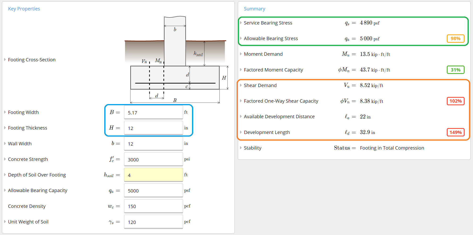
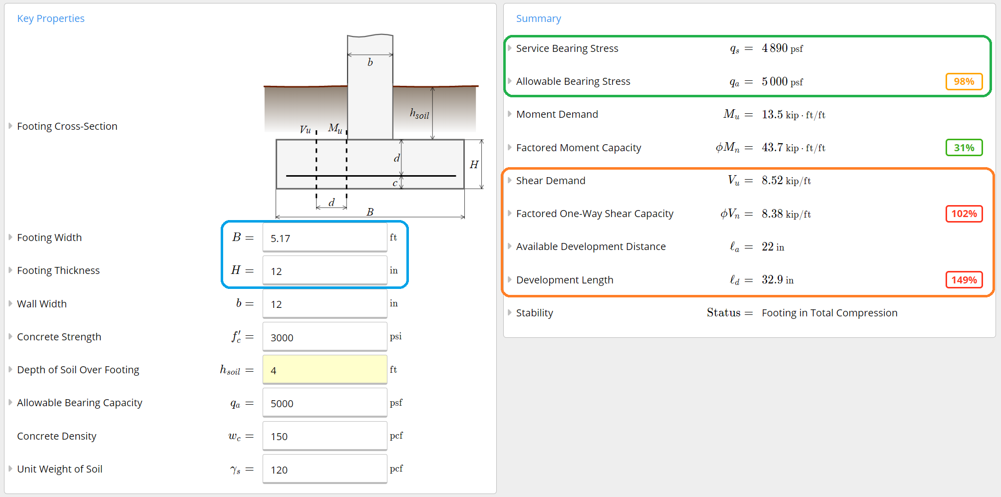
3
Shear Capacity
After the little sneak peek we saw when checking soil bearing, we definitely want to take a look at shear. This is usually what will govern the footing’s thickness in design. Since we are now dealing with concrete design, we use the ACI 318-14 standard, which is based on LRFD design. We thus need to factor the loads.We can find a value for , the soil pressure at the factored load level, by dividing our total applied load by the footing area. In this case since we only have dead and live loads, it is clear that the governing load combination will be 1.2D + 1.6L.Note that we are taking the net bearing pressure, which does not include the weight of the soil above the footing and the self-weight. This is because these weights are canceled out by their corresponding upwards soil reaction when considering the footing as a free-body.With our new-found value of , we can find the factored shear. The ACI-318-14 code (*Cl 7.4.3.2*) specifies that the critical shear section should be taken at a distance from the face of the wall. With our 12-inch thick footing, we need a minimum of 3 inches cover (*ACI 318-14, Table 20.6.1.3.1*). Assuming #8 size reinforcement (1” diameter), we can find d:We can now calculate the shear at the critical section:We must now find the shear resistance. Footings almost never have shear reinforcement - it is usually preferable to increase the footing thickness. We thus only need to calculate the factored concrete shear strength , which is given by ACI 318-14 Cl 22.5.5.1:For shear, ACI 318-14 Table 21.2.1 specifies and we’re using normal-weight concrete so .As we had predicted with Calcs.com in the previous section, we find that . At this point, we could either increase the concrete strength, increase the footing thickness or decide to add shear reinforcement. As previously discussed, shear reinforcement is usually avoided in footings and the concrete strength was already specified, so we choose to increase the thickness.Increasing the thickness benefits shear resistance in two ways. First, it increases the capacity by providing a greater value of . It also reduces the applied shear load since we are taking our critical section further away from the wall face. We pick a 13-inch thick footing and repeat the previous steps:We see that the 1-inch increase both decreased and increase as we liked. Verifying with Calcs.com, we can now look at the results again with a 13-inch thick footing:  We see that we went down from 102% to 85% utilization in shear, and the increase in bearing stress was negligible.
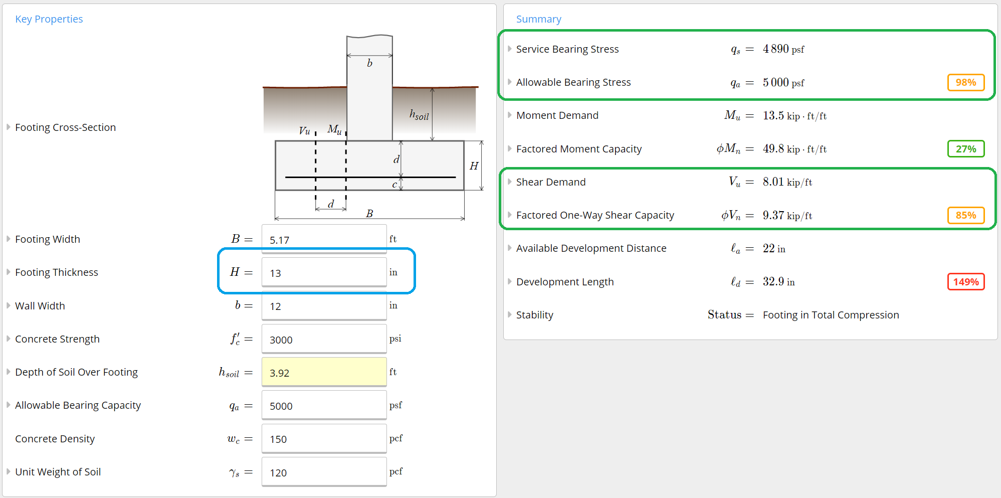 We see that we went down from 102% to 85% utilization in shear, and the increase in bearing stress was negligible.
4
Flexural Capacity
The last failure mode which we need to check is the bending of the footing. We essentially have a cantilevered out concrete slab, with a uniformly distributed load from the soil’s upward pressure. In the code, it is specified that we should take our critical section for bending at the column face (*ACI 318-14, Cl 13.2.7.1*). We can thus easily calculate the bending moment, using the typical equation for a cantilever beam:Using the familiar approximation to find the required area of steel (with in and in inches):Note that the Reinforced Concrete Mechanics and Design textbook makes use of a slightly less conservative approximation and finds . We must also verify that we are meeting minimum steel area requirements are met:And the maximum spacing is the minimum of and 18 inches - the latter usually governs for footings. With these criteria in mind, we can select our reinforcement - using the textbook’s approximation for required steel area, we find we can use either #5 bars at 11 inches O.C. or #4 bars at 7 inches, which both provide . Finding the actual moment resistance now:With such a small value of , it’s clear that our footing will be tension controlled and thus . We can find the moment capacity.Note that in this example, was kept at 9.5 inches even though it would be slightly larger, since we are using #4 bars with half the diameter . This is conservative and simplifies calculations somewhat. Nevertheless, we see that so our design is adequate.Checking with Calcs.com:  We can clearly see that indeed we have a higher capacity. Note that we automatically calculate the depth to reinforcement - thus the increase in from using a smaller bar is automatically calculated which provides us with slightly more capacity! Opening our size selector (the filter button circled in dark blue), we see that at this spacing, #4 bars are the most optimal.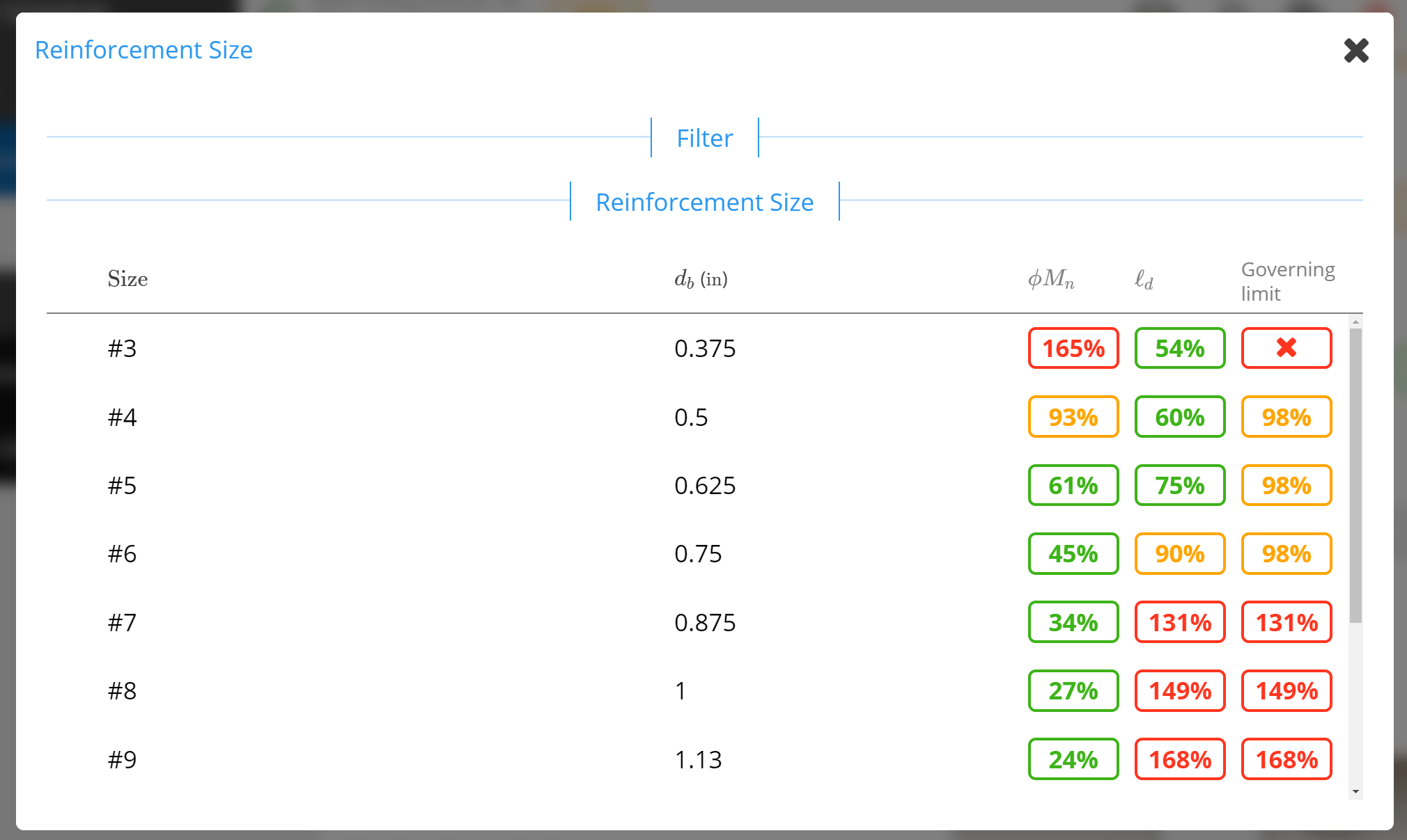
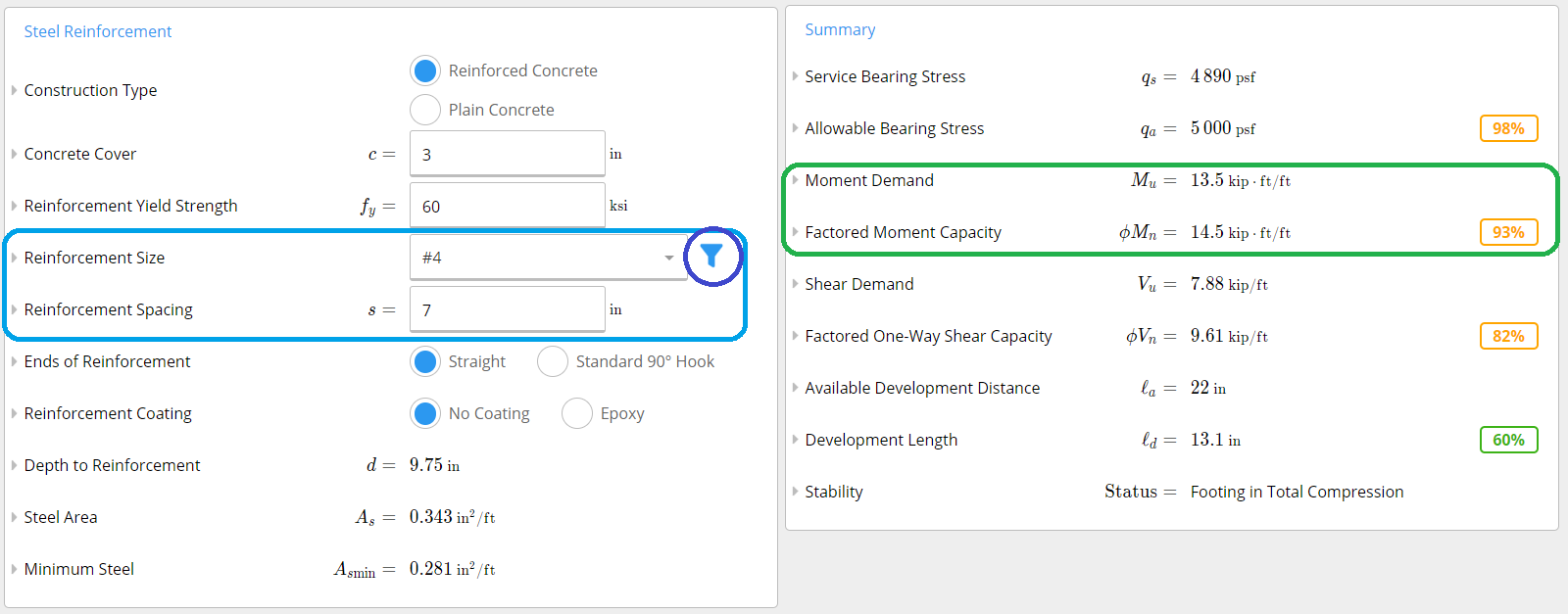 We can clearly see that indeed we have a higher capacity. Note that we automatically calculate the depth to reinforcement - thus the increase in from using a smaller bar is automatically calculated which provides us with slightly more capacity! Opening our size selector (the filter button circled in dark blue), we see that at this spacing, #4 bars are the most optimal.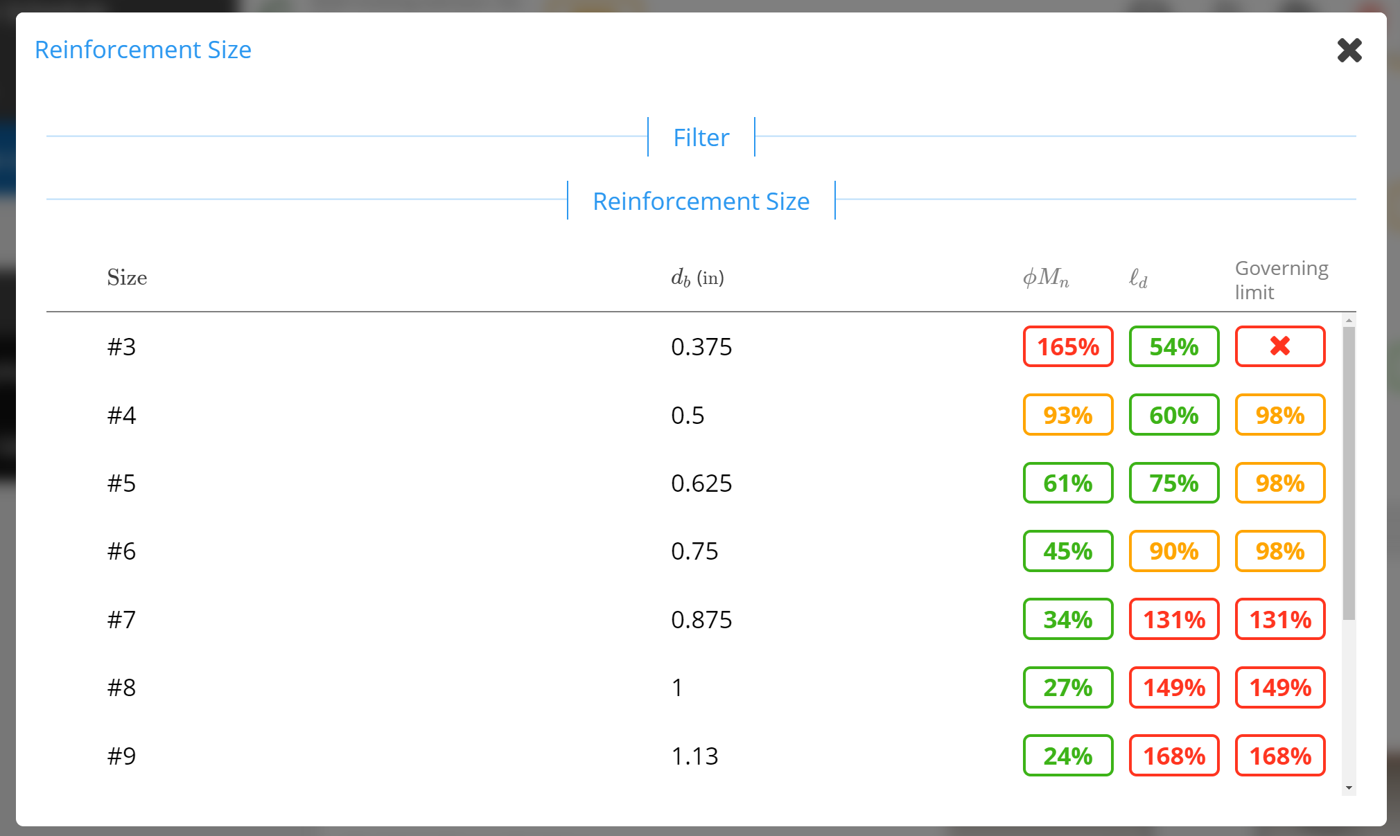
5
Development of Reinforcement
The last check we perform is on the development length, to ensure we have proper bonding of our reinforcement at the critical section. We go to ACI 314-18’s chapter 25 to calculate the bonding length. For simplicity, we use Table 25.4.2.2, which gives a simple equation to calculate the development length. We are using a No.4 bar with large spacing, so we can use the least conservative formula as per the table. In this case neither the epoxy or casting position factors which further simplifies our calculation.We find the same value as in the textbook’s example. We compare this to the distance to the critical section:Since 25 inches is larger than 21.9 inches, we know our bars are developed as required. Had this not been the case, we could have used hooks at the ends of the bar to significantly reduce the development length, or made use of the more detailed calculations which can be less conservative and more accurate. With Calcs.com, it is just as easy to perform the more detailed calculations of development length, so this is what to do to provide safe and economical designs.  The development length is reduced by a huge margin when using the detailed equation! This mostly comes from the confinement factor, since our footing has large cover and spacing between bars this greatly benefits the development length.
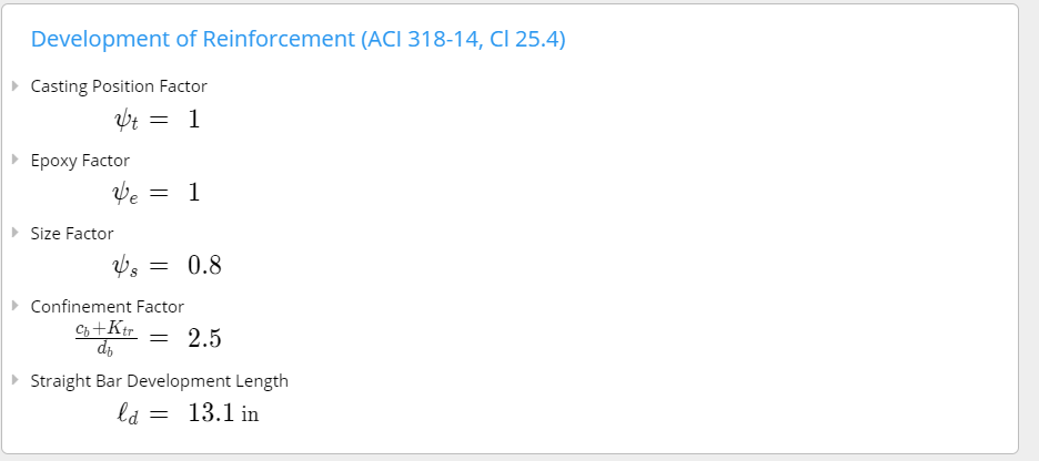 The development length is reduced by a huge margin when using the detailed equation! This mostly comes from the confinement factor, since our footing has large cover and spacing between bars this greatly benefits the development length.
US Wall Footing: Overview
US Wall Footing: Example
Common questions
What design standard does this calculator use?
What design standard does this calculator use?
The calculator applies ACI 318-19 for reinforced concrete section design, with load combinations from ASCE 7-16 (IBC 2021) or ASCE 7-22 (IBC 2024) as selected. Both strength design (LRFD) and bearing pressure serviceability checks are performed, with all code clause references shown in the output.
What are the key inputs?
What are the key inputs?
Key inputs are wall thickness, footing width and depth, concrete compressive strength (f’c), reinforcement bar size and spacing, concrete cover, allowable soil bearing pressure (qa), and applied loads per unit length of wall (axial force, overturning moment, shear). Loads can be entered directly or linked from a wall calculation above.
What does the calculator check and output?
What does the calculator check and output?
Checks include: bearing pressure under service loads versus allowable bearing capacity, ultimate flexural demand at the face of the wall versus design moment capacity (phiMn), one-way shear at the critical section (d from the wall face) versus shear capacity (phiVc), and minimum reinforcement per ACI 318-19 Section 13.3. Required and provided reinforcement areas are reported.
What is the difference between this calculator and the ACI 318-14 version?
What is the difference between this calculator and the ACI 318-14 version?
The ACI 318-19 version includes the updated provisions from the 2019 edition, including revised shear design equations (ACI 318-19 Table 22.5.5.1 using the size effect factor lambda-s) and updated minimum reinforcement requirements. For projects under IBC 2021 or newer, use this ACI 318-19 version. For legacy IBC 2018 projects, use the Wall Footing (ACI 318-14) calculator.
Can I link wall loads directly from a wall or column calculation?
Can I link wall loads directly from a wall or column calculation?
Yes. Axial force, moment, and shear at the base of the wall can be linked from a connected wall or column calculator in the same project. When loads change upstream, the footing recalculates bearing pressure, flexure, and shear automatically, no manual re-entry of reactions needed.
Does this calculator support load linking from walls above?
Does this calculator support load linking from walls above?
Yes. Bearing pressure, flexural demand, and shear demand all update automatically when the wall above changes. For multi-story walls where each floor adds to the footing load, link the governing load combination from the critical wall calculation to keep the footing design synchronized with the rest of the load path.
Next steps
Design a Combined Footing to ACI 318-19
Design combined rectangular footings for two columns to ACI 318-19 per IBC 2024: bearing, overturning, sliding, flexure, shear and development length.
Design a Spread Footing (IBC 2024)
Design isolated spread footings to ACI 318-19 per IBC 2024 (ASCE 7-22): bearing, flexure, one-way and punching shear, and development length.
Spread Footing to ACI 318-14 - Validation Examples
Validation and design examples for concrete spread footings to ACI 318-14.