United StatesIBC 2024ASCE 7-22ACI 318-19

Cantilever Retaining Wall (IBC 2024)

Run the calc
Adding a shear key to a retaining wall can lower the sliding factor of safety or leave it almost unchanged. The Cantilever Retaining Wall (IBC 2024) calculator adds active soil pressure on the key by default, as well as the passive resistance the key provides. This article works through a 10 ft wall with a 12 in key, and shows how to leave the active pressure on the key out.

Worked example

Symbols

The worked example uses these symbols.

Example 1: a 10 ft wall with a 12 in shear key

A 10 ft retaining wall on a 12 in thick footing is checked for sliding three ways: with no shear key, with a 12 in key, and with the key’s active pressure left out. The run starts from the Fully-Drained Retaining Wall preset of Cantilever Retaining Wall (IBC 2024), version 1, in a US customary project. The soil pressures are entered as equivalent fluid pressures, 40 psf/ft active and 150 psf/ft passive, as shown in the diagram. Retaining wall example with a 10 ft retained height, a 1 ft footing and a 1 ft shear key, showing active pressure of 40 psf per ft and passive pressure of 150 psf per ft The run changes these inputs from the preset:
  • Wall Height and Height of Backfill: 10 ft, from 8 ft
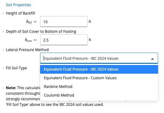
  • Lateral Pressure Method: Equivalent Fluid Pressure - Custom Values, from Equivalent Fluid Pressure - IBC 2024 Values
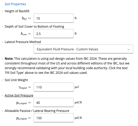
  • Active Soil Pressure: 40 psf/ft, and Allowable Passive / Lateral Bearing Pressure: 150 psf/ft
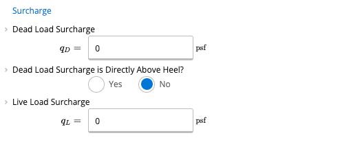
  • Live Load Surcharge: 0 psf, from 100 psf
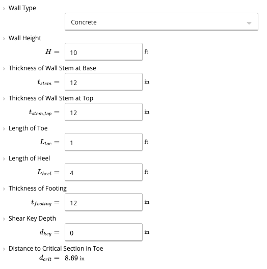
  • Shear Key Depth: 0 in for the first check, then 12 in
Everything else stays as it starts, including the 12 in footing, the 1 ft toe, the 4 ft heel, the 12 in stem, the Soil Unit Weight of 110 pcf and the Soil-Footing Friction Coefficient of 0.25.
1

Set the wall height

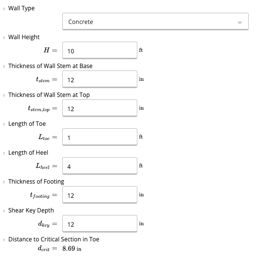
In Key Dimensions, change the Wall Height to 10 ft. In Soil Properties, change the Height of Backfill to 10 ft. The Shear Key Depth stays 0 in for now.Key Dimensions with a Wall Height of 10 ft, a stem thickness of 12 in at the base and the top, a toe of 1 ft, a heel of 4 ft, a footing thickness of 12 in and a Shear Key Depth of 0 in.
2

Set the soil pressures

In Soil Properties, open the Lateral Pressure Method list and choose Equivalent Fluid Pressure - Custom Values. Three inputs appear: the Soil Unit Weight, the Active Soil Pressure and the Allowable Passive / Lateral Bearing Pressure. Enter 40 psf/ft and 150 psf/ft for the last two.Lateral Pressure Method list open, with the options Equivalent Fluid Pressure - IBC 2024 Values, Equivalent Fluid Pressure - Custom Values, Rankine Method and Coulomb Method.Soil Properties with a Height of Backfill of 10 ft, a Depth of Soil Cover of 2.5 ft, the custom values method, a Soil Unit Weight of 110 pcf, an Active Soil Pressure of 40 psf/ft and a Passive Bearing Pressure of 150 psf/ft.
3

Remove the live load surcharge

In Surcharge, change the Live Load Surcharge to 0 psf, so the only lateral load is the soil.Surcharge with a Dead Load Surcharge of 0 psf, the Directly Above Heel option set to No and a Live Load Surcharge of 0 psf.
4

Read the results with no key

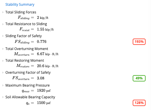
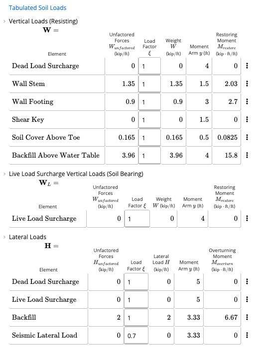
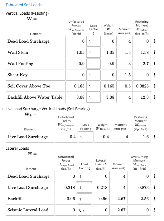
The Stability Summary shows Total Sliding Forces (FslidingF_{sliding}) of 2 kip/ft, a Total Resistance to Sliding (FresistF_{resist}) of 1.55 kip/ft and a Sliding Factor of Safety (FSslidingFS_{sliding}) of 0.776, with a red 193% badge.Stability Summary with Total Sliding Forces of 2 kip/ft, a Total Resistance to Sliding of 1.55 kip/ft and a Sliding Factor of Safety of 0.776 with a red 193 percent badge, an Overturning Factor of Safety of 3.08 and a Maximum Bearing Pressure of 1920 psf.In Tabulated Soil Loads, the Lateral Loads table shows the backfill at 2 kip/ft.Tabulated Soil Loads with the vertical loads of the wall stem, footing, soil cover above the toe and backfill, the live load surcharge, and the lateral loads, with a backfill lateral load of 2 kip/ft.
5

Add the shear key

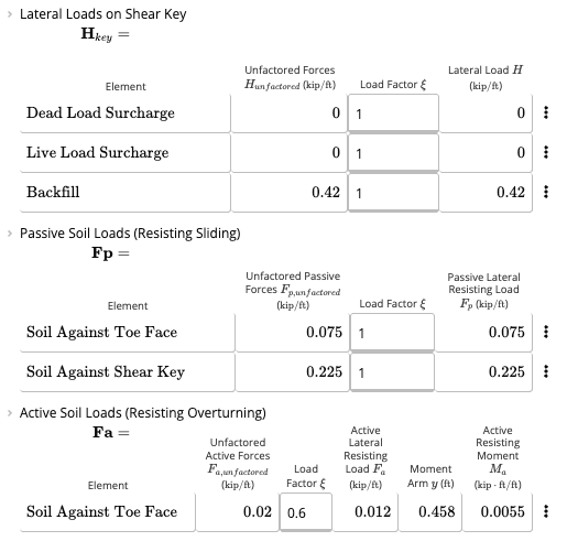
In Key Dimensions, change the Shear Key Depth to 12 in.Key Dimensions with a Shear Key Depth of 12 in and the other dimensions unchanged.Tabulated Soil Loads now shows the Lateral Loads on Shear Key table, with a backfill load of 0.42 kip/ft, and the Passive Soil Loads (Resisting Sliding) table, with 0.075 kip/ft on the toe face and 0.225 kip/ft on the shear key. The Shear Key row of the vertical loads is now 0.15 kip/ft.Lateral Loads on Shear Key with a backfill load of 0.42 kip/ft, Passive Soil Loads with 0.075 kip/ft against the toe face and 0.225 kip/ft against the shear key, and Active Soil Loads for the overturning check.
6

Read the results with the key

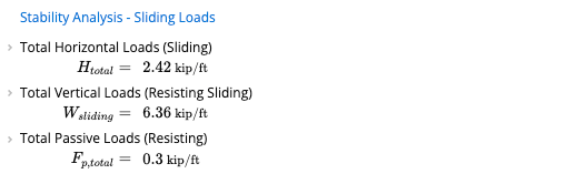
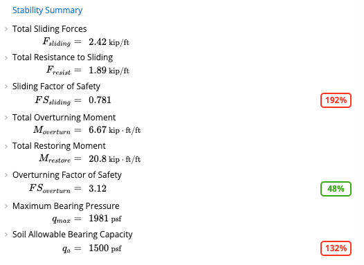
Stability Analysis - Sliding Loads shows Total Horizontal Loads (Sliding) of 2.42 kip/ft, Total Vertical Loads (Resisting Sliding) of 6.36 kip/ft and Total Passive Loads (Resisting) of 0.3 kip/ft.Stability Analysis - Sliding Loads with Total Horizontal Loads (Sliding) of 2.42 kip/ft, Total Vertical Loads (Resisting Sliding) of 6.36 kip/ft and Total Passive Loads (Resisting) of 0.3 kip/ft.The Stability Summary shows Total Sliding Forces of 2.42 kip/ft, a Total Resistance to Sliding of 1.89 kip/ft and a Sliding Factor of Safety of 0.781. The shear key added 0.42 kip/ft of driving force and 0.34 kip/ft of resistance, so the factor of safety barely moved.Stability Summary with Total Sliding Forces of 2.42 kip/ft, a Total Resistance to Sliding of 1.89 kip/ft and a Sliding Factor of Safety of 0.781 with a red 192 percent badge.
7

Leave out the active pressure on the key
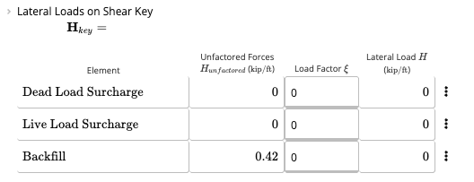
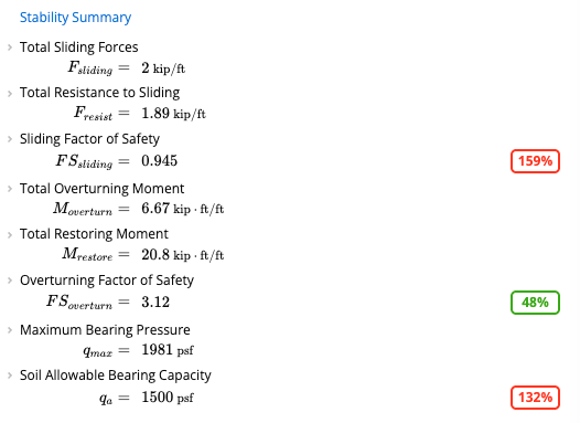
In Tabulated Soil Loads, in the Lateral Loads on Shear Key table, change the Load Factor of the Dead Load Surcharge, Live Load Surcharge and Backfill rows to 0. The backfill load on the key drops from 0.42 kip/ft to 0.Lateral Loads on Shear Key with the Load Factor of the Dead Load Surcharge, Live Load Surcharge and Backfill rows set to 0, and a backfill lateral load of 0 kip/ft.The Stability Summary now shows Total Sliding Forces of 2 kip/ft, a Total Resistance to Sliding of 1.89 kip/ft and a Sliding Factor of Safety of 0.945.Stability Summary with Total Sliding Forces of 2 kip/ft, a Total Resistance to Sliding of 1.89 kip/ft and a Sliding Factor of Safety of 0.945 with a red 159 percent badge.
Inputs, Calcs.com output and a hand check

Inputs

CalculatorCantilever Retaining Wall (IBC 2024)
PresetFully-Drained Retaining Wall
Wall height, backfill height10 ft
Footing thickness12 in
Shear key depth0 in, then 12 in
Active soil pressure40 psf/ft
Passive bearing pressure150 psf/ft
Friction coefficient μ\mu0.25
Live load surcharge0 psf

Calcs.com output

No key: FslidingF_{sliding}, FresistF_{resist}2 and 1.55 kip/ft
No key: FSslidingFS_{sliding}0.776
12 in key: FslidingF_{sliding}, FresistF_{resist}2.42 and 1.89 kip/ft
12 in key: FSslidingFS_{sliding}0.781
Key load factors 0: FslidingF_{sliding}, FresistF_{resist}2 and 1.89 kip/ft
Key load factors 0: FSslidingFS_{sliding}0.945

Hand check

✓No key: Pa=1/2×40×102=2000P_a = 1/2 \times 40 \times 10^2 = 2000 lb/ft, which is 2 kip/ft
✓No key: the sheet takes W=1.35+0.9+3.96=6.21W = 1.35 + 0.9 + 3.96 = 6.21 kip/ft from the stem, footing and backfill (the 0.165 kip/ft of soil above the toe is not counted by default), so friction gives 0.25×6.21=0.25 \times 6.21 = 1.55 kip/ft and FSsliding=1.55/2=FS_{sliding} = 1.55 / 2 = 0.776
✓12 in key, active load: the key adds 1/2×40×(112−102)=4201/2 \times 40 \times (11^2 - 10^2) = 420 lb/ft, so Fsliding=2+0.42=F_{sliding} = 2 + 0.42 = 2.42 kip/ft
✓12 in key, passive load: 1/2×150×12=751/2 \times 150 \times 1^2 = 75 lb/ft on the toe face and 1/2×150×(22−12)=2251/2 \times 150 \times (2^2 - 1^2) = 225 lb/ft on the key, so Pp=P_p = 0.3 kip/ft
✓12 in key, resistance: the key weighs 0.15 kip/ft, so W=6.21+0.15=6.36W = 6.21 + 0.15 = 6.36 kip/ft and Fresist=0.25×6.36+0.3=F_{resist} = 0.25 \times 6.36 + 0.3 = 1.89 kip/ft. Then FSsliding=1.89/2.42=FS_{sliding} = 1.89 / 2.42 = 0.781
✓Key load factors 0: FSsliding=1.89/2=FS_{sliding} = 1.89 / 2 = 0.945
✓The key added 0.34 kip/ft of resistance and 0.42 kip/ft of driving force. 0.34/0.42=0.810.34 / 0.42 = 0.81 is close to the 0.776 without the key, so the factor of safety barely changes

The loads, resistance and factors of safety match the closed-form solution, using the sheet’s vertical loads and friction coefficient. This is a sanity check only. Cantilever Retaining Wall (IBC 2024) version 1.

Overview

In some cases, adding a shear key to a retaining wall design can unexpectedly reduce the sliding factor of safety (FoS) instead of improving it, or leave it almost unchanged. This behavior is not a bug in the Retaining Wall module. It reflects how soil pressures are calculated on both sides of the key.

How the Shear Key Affects Sliding Forces

When a shear key is added:
  • Active Pressure Increases
    The soil on the backfill side exerts active pressure on the key.
    This pressure is calculated based on the total height from the backfill surface to the bottom of the key.
    Example: If you have 7 ft of backfill plus a 2 ft deep key, the active pressure is calculated over a total height of 9 ft.
  • Passive Pressure Increases
    On the opposite side, soil provides passive resistance to sliding.
    This is typically calculated from the soil in front of the footing.
    Note: By default, we ignore cover soil above the footing because it can be disturbed during construction, which further reduces the countering effect of passive pressure. This can be overridden with the “Consider Soil Above Toe for Stability Checks?” option in the calculator.
These effects counteract each other and can lead to unintuitive results, as the worked example shows.

Why Shallow Keys Can Reduce FoS

When the key depth is small:
  1. Active pressure grows quickly because it is based on a taller soil column behind the wall (backfill + key depth).
  2. Passive resistance grows more slowly because it is based only on the depth of undisturbed soil in front of the footing.
  3. As a result, the increase in sliding force from active pressure can outpace the gain in resistance from passive pressure.
    A key lowers the sliding FoS when the resistance it adds, divided by the driving force it adds, is less than the FoS without the key. In the worked example that ratio is 0.81 against an FoS of 0.776, so the key barely helps.

How to use it

These steps cover the Cantilever Retaining Wall (IBC 2024) inputs that affect a sliding check with a shear key. The values shown are the Fully-Drained Retaining Wall preset as it opens.
1

Open the calculator and pick a preset

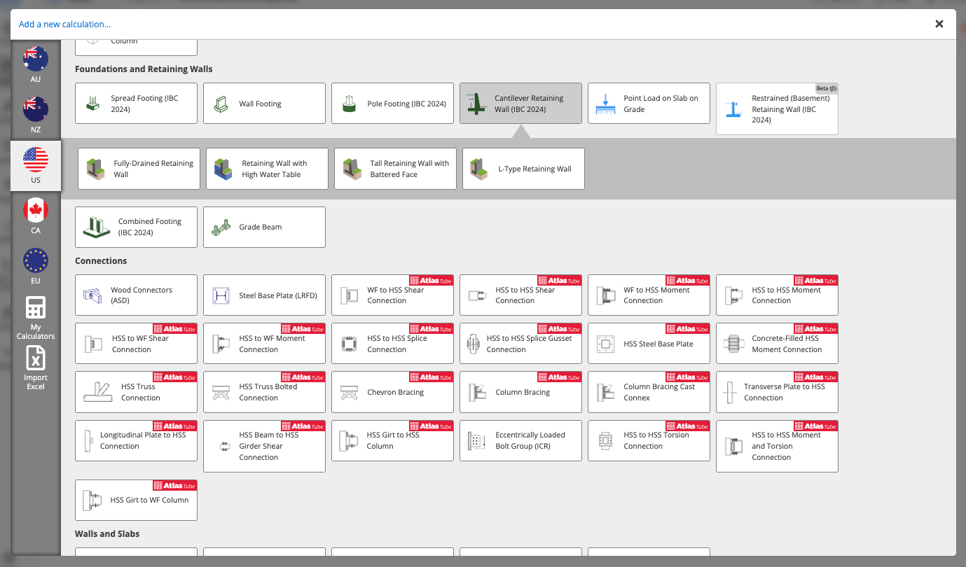
In a project, select + Add New Calculation and choose the US tab. Under Foundations and Retaining Walls, select Cantilever Retaining Wall (IBC 2024). Four presets open below it: Fully-Drained Retaining Wall, Retaining Wall with High Water Table, Tall Retaining Wall with Battered Face and L-Type Retaining Wall. Select Fully-Drained Retaining Wall.Add a new calculation window on the US tab with Cantilever Retaining Wall (IBC 2024) selected and four presets open below it.
2

Read the assumptions

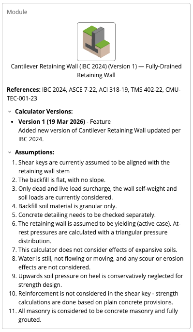
The Module panel lists the references and 11 assumptions. Three matter for shear keys: the shear key is assumed to be aligned with the stem (assumption 1), the wall is assumed to be yielding, so the active case applies (assumption 6), and reinforcement is not considered in the shear key (assumption 10).Module panel for the Fully-Drained Retaining Wall preset, version 1, with its references and 11 assumptions.
3

Set the key dimensions

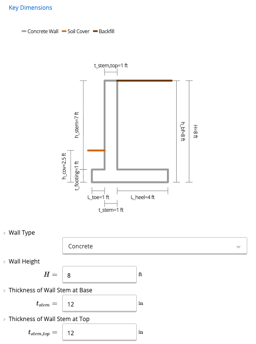
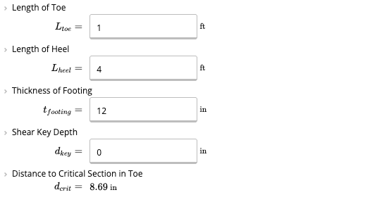
In Key Dimensions, set the Wall Height, the thickness of the wall stem at the base and the top, the length of the toe and the heel, the footing thickness and the Shear Key Depth. The diagram above the inputs updates as you type. The preset opens with a wall height of 8 ft, a 12 in stem, a 1 ft toe, a 4 ft heel, a 12 in footing and no shear key.Key Dimensions with a diagram of the wall, and the inputs Wall Type Concrete, Wall Height 8 ft, stem thickness 12 in at the base and the top.Length of Toe 1 ft, Length of Heel 4 ft, Thickness of Footing 12 in and Shear Key Depth 0 in, with a calculated Distance to Critical Section in Toe of 8.69 in.
4

Set the soil

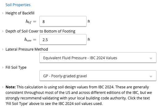
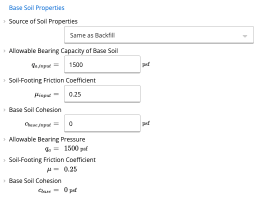
In Soil Properties, set the Height of Backfill, the Depth of Soil Cover to Bottom of Footing and the Lateral Pressure Method. The method can be Equivalent Fluid Pressure with IBC 2024 values, Equivalent Fluid Pressure with custom values, Rankine or Coulomb. The preset opens with an 8 ft backfill, 2.5 ft of cover, the IBC 2024 values and a GP poorly-graded gravel fill.Soil Properties with a Height of Backfill of 8 ft, a Depth of Soil Cover of 2.5 ft, the Equivalent Fluid Pressure - IBC 2024 Values method and a GP poorly-graded gravel fill.In Base Soil Properties, check the allowable bearing capacity of the base soil, the Soil-Footing Friction Coefficient and the base soil cohesion. Friction is part of the sliding resistance. The preset opens with 1500 psf, 0.25 and 0 psf, with the source set to Same as Backfill.Base Soil Properties with the source Same as Backfill, an allowable bearing capacity of 1500 psf, a friction coefficient of 0.25 and a cohesion of 0 psf.
5

Set the surcharge and seismic load

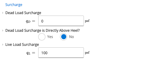
In Surcharge, set the Dead Load Surcharge, whether it is directly above the heel, and the Live Load Surcharge. The live load surcharge adds lateral load and bearing load but does not help resist sliding or overturning. The preset opens with 0 psf, No and 100 psf. In Seismic Loads, choose whether to apply a seismic lateral load. The preset opens with No.Surcharge with a Dead Load Surcharge of 0 psf, the Directly Above Heel option set to No and a Live Load Surcharge of 100 psf.Seismic Loads with the question Apply Seismic Lateral Load set to No.
6

Set the water table

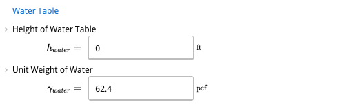
In Water Table, set the Height of Water Table and the Unit Weight of Water. The preset opens with 0 ft and 62.4 pcf. With a shear key, setting the water level to 0 ft does not treat the key as submerged.Water Table with a Height of Water Table of 0 ft and a Unit Weight of Water of 62.4 pcf.
7

Review the design criteria

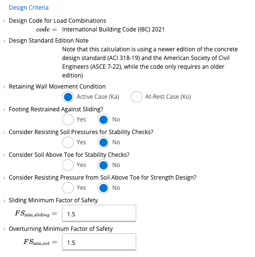
In Design Criteria, check the Retaining Wall Movement Condition (Active Case or At-Rest Case), whether the footing is restrained against sliding, and the soil options for the stability checks. Passive soil pressure is not considered by default unless a shear key is specified, and Consider Resisting Soil Pressures for Stability Checks? overrides that. Consider Soil Above Toe for Stability Checks? adds the pressure from the soil above the toe. The minimum factors of safety for sliding and overturning are 1.5.Design Criteria with the Active Case selected, Footing Restrained Against Sliding set to No, the three Consider soil options set to No, and minimum factors of safety of 1.5 for sliding and overturning.
8

Check the reinforcement

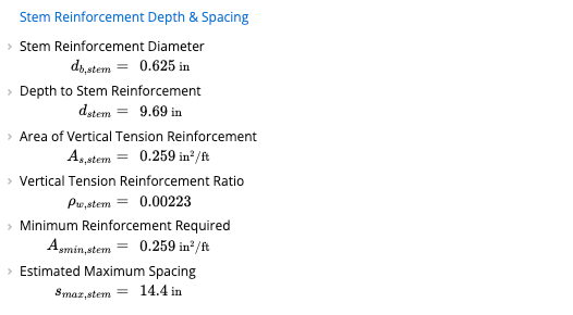
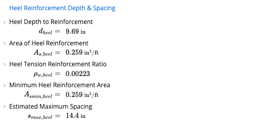
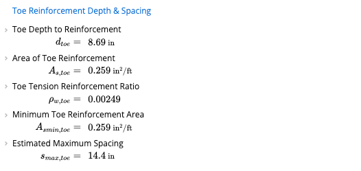
The Stem, Heel and Toe Reinforcement Depth & Spacing panels show the reinforcement depth, area, reinforcement ratio, minimum area and estimated maximum spacing.Stem Reinforcement Depth & Spacing with a bar diameter of 0.625 in, a depth of 9.69 in, an area of 0.259 in squared per ft, a ratio of 0.00223, a minimum area of 0.259 in squared per ft and a maximum spacing of 14.4 in.Heel Reinforcement Depth & Spacing with a depth of 9.69 in, an area of 0.259 in squared per ft, a ratio of 0.00223, a minimum area of 0.259 in squared per ft and a maximum spacing of 14.4 in.Toe Reinforcement Depth & Spacing with a depth of 8.69 in, an area of 0.259 in squared per ft, a ratio of 0.00249, a minimum area of 0.259 in squared per ft and a maximum spacing of 14.4 in.
9

Read the results

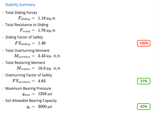
The Stability Summary shows the sliding force, the resistance to sliding, the sliding factor of safety, the overturning moment and factor of safety, and the bearing pressure. For the preset as it opens, the sliding factor of safety is 1.49, below the minimum of 1.5. Tabulated Soil Loads lists the vertical loads and the lateral loads with a load factor on each row.Stability Summary for the preset as it opens, with Total Sliding Forces of 1.18 kip/ft, a Total Resistance to Sliding of 1.76 kip/ft and a Sliding Factor of Safety of 1.49 with a red 100 percent badge.Tabulated Soil Loads with the vertical loads of the wall stem, footing, soil cover above the toe and backfill, the live load surcharge, and the lateral loads with a load factor on each row.

Calcs.com Workaround: Ignore active pressure on shear key

By default, we take the conservative approach of including active soil pressure against the shear key. If you do not want this in your calculations, you can:
  1. Go to Tabulated Soil Loads and find the Lateral Loads on Shear Key table. It appears once the Shear Key Depth is above 0.
  2. Set the Load Factor of the rows to 0.
This will effectively ignore the active pressure contribution from the key. Step 7 of the worked example shows the result. Screen recording of the Lateral Loads on Shear Key table, with the load factors set to 0

Building Code Considerations

Some building codes explicitly require considering the active pressure acting on the key. In general, building codes based on the 2015 edition of the IBC and earlier contain the following phrase (see in 2015 IBC):
Where a keyway is extended below the wall base with the intent to engage passive pressure and enhance sliding stability, lateral soil pressures on both sides of the keyway shall be considered in the sliding analysis.
Starting in 2018, the IBC no longer includes that clause, but a few jurisdictions retain it in their local codes. In the IBC 2018 change notes, the following explanation is given:
The application of soil pressure on both sides of a keyway is a recent addition to the model codes, and has caused concern and opposition from the geotechnical engineering community. The keyway concept is in conflict with accepted engineering practice and the principles of soil mechanics. 2015 IBC language was vague and ambiguous with respect to lateral soil pressures on the keyway. The application of “lateral earth pressures on both sides of the keyway” is commonly interpreted to require a deepening of the active soil pressure to the bottom of the keyway. Active soil pressure requires movement of the key, which is contrary to the intent of the provision. As there has been ongoing confusion over the intent of consideration of lateral earth pressure on both sides of the keyway and confusion about the purpose of the keyway, in the 2018 IBC the requirement for a keyway is deleted. A keyway may still be used when designed using the principles of soil mechanics and accepted engineering practice.
We’ve put together a non-exhaustive list of building codes requiring active pressure on shear key below:

Common questions

The calculator adds the active pressure on the key to the sliding force and the passive pressure on the key to the resistance. The key lowers the sliding factor of safety when the added resistance divided by the added driving force is less than the factor of safety without the key. In the worked example the key adds 0.34 kip/ft of resistance and 0.42 kip/ft of driving force, a ratio of 0.81 against a factor of safety of 0.776 without the key.
In Tabulated Soil Loads, set the Load Factor of the rows of the Lateral Loads on Shear Key table to 0. Check that your local code allows this first, because some codes require active pressure on the key (see the table above).
Not by default. Passive pressure is not considered unless a shear key is specified. You can change this with the “Consider Resisting Soil Pressures for Stability Checks?” option in Design Criteria.
Not by default. Cover soil above the footing can be disturbed during construction, so it is ignored. You can change this with the “Consider Soil Above Toe for Stability Checks?” option in Design Criteria.

Next steps

Design a Cantilever Retaining Wall (IBC 2024)

Design concrete or CMU cantilever retaining walls to IBC 2024, ASCE 7-22, ACI 318-19 and TMS 402-22, with shear key design and seismic loads.

CMU Cantilever Retaining Wall Worked Example

Worked example: a reinforced CMU cantilever wall retaining 9 ft of earth, checked for bending and shear in the Cantilever Retaining Wall (IBC 2024) calculator.