Overview
In Calcs.com, the structural design process is often separated into two stages:- Analysis: Calculating forces (Demands) like displacements, moments, and shears based on geometry and stiffness. This is handled by the Truss Analysis Wizard or Portal Frame Analysis.
- Design: Checking if a specific member size can withstand those forces (Capacity) using a Design Only calculator.
Here are the specific steps for both workflows.
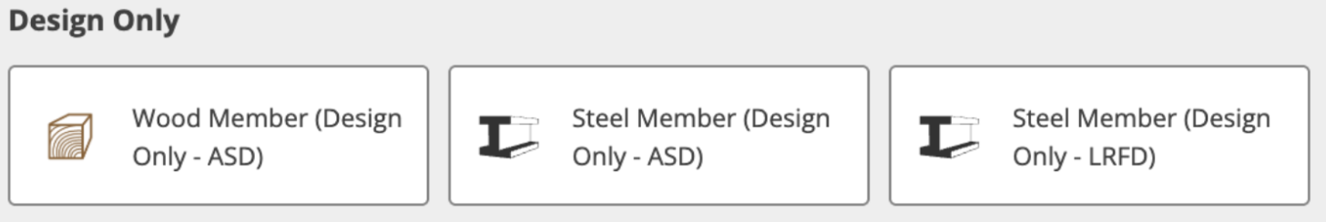
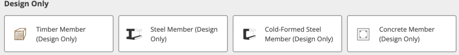
Currently, Calcs.com has Design Only modules available for the materials below.
US Calculators:
The Linking Workflow
Whether you are designing a steel warehouse frame or a timber roof truss, the workflow is identical.1
Run the Analysis
Set up your geometry and loads in either the Truss Analysis Wizard or the Portal Frame Analysis calculator. This will generate your raw results: displacements, moments, and shears.
2
Create a Design Calculator
Click Add New Calculation and select a Design Only module appropriate for your material (e.g., Timber Member (Design Only), Steel Beam (Design Only), or Cold Form Steel depending on the country).
3
Link the Forces
Find the “Loads” section in the Design calculator. Click the Link button (chain icon). Select your Analysis calculation as the source, and choose the specific member (e.g., “Top Chord” or “Left Leg”).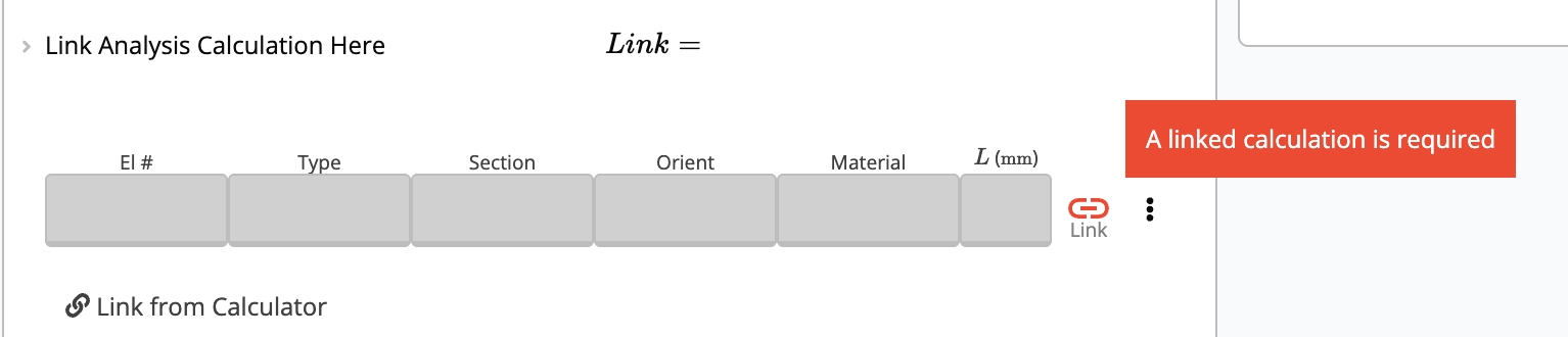
Example A: Truss Analysis (Steel & Wood)
The Truss Analysis Wizard is strictly an FEA engine, it tells you how much force is in a member, but not if the member will break. Linking allows you to check code compliance.1. Steel Truss Member
Scenario: Checking the Top Chord of a Flat Pratt Truss.1
Define Geometry
In the Truss Analysis Wizard, go to the Truss Geometry section:
- Set Truss Type to “Flat Pratt Truss”.
2
Apply Loads
Scroll to the Distributed Loads on Chords section: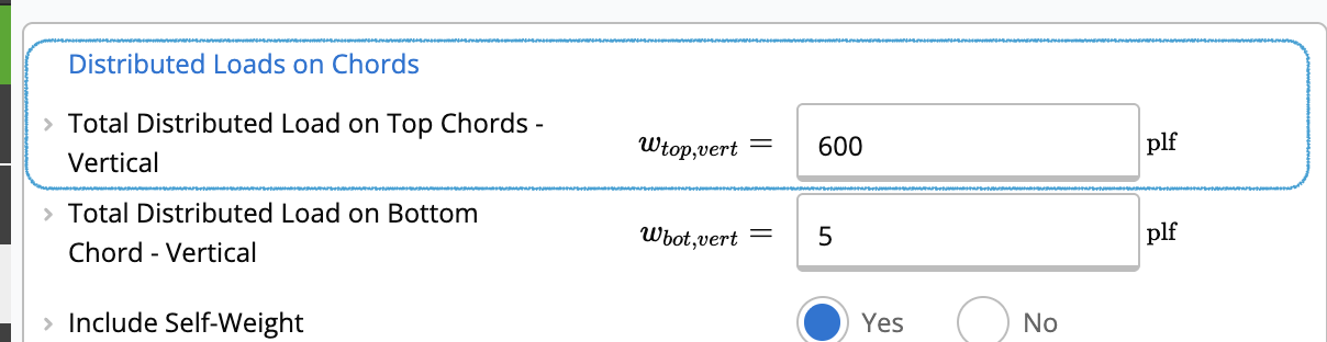
- Enter the load value in Total Distributed Load on Top Chords - Vertical (e.g., 600 plf for a downward gravity load).
3
Select Members
Scroll down to the Member Selection section:
- Set Truss Material to “Hot-Rolled Steel & RHS/SHS”.
- Go to Top Chord Member and select your preliminary section (e.g., “HSS10X3X5/16”).
4
Create Design Calculation
Go to the main menu and create a new Steel Beam (Design Only) calculator.
5
Link Forces
In the new Design calculator, locate the Loads table. Click the Link button (chain icon), select your Truss Analysis calculation as the source, and choose “Top Chord”.
6
Check Capacity
The calculator automatically imports the worst-case Axial Compression (C), Axial Tension (T), Strong Axis Moment (Mx) and other properties.Verify the Summary section to ensure the selected 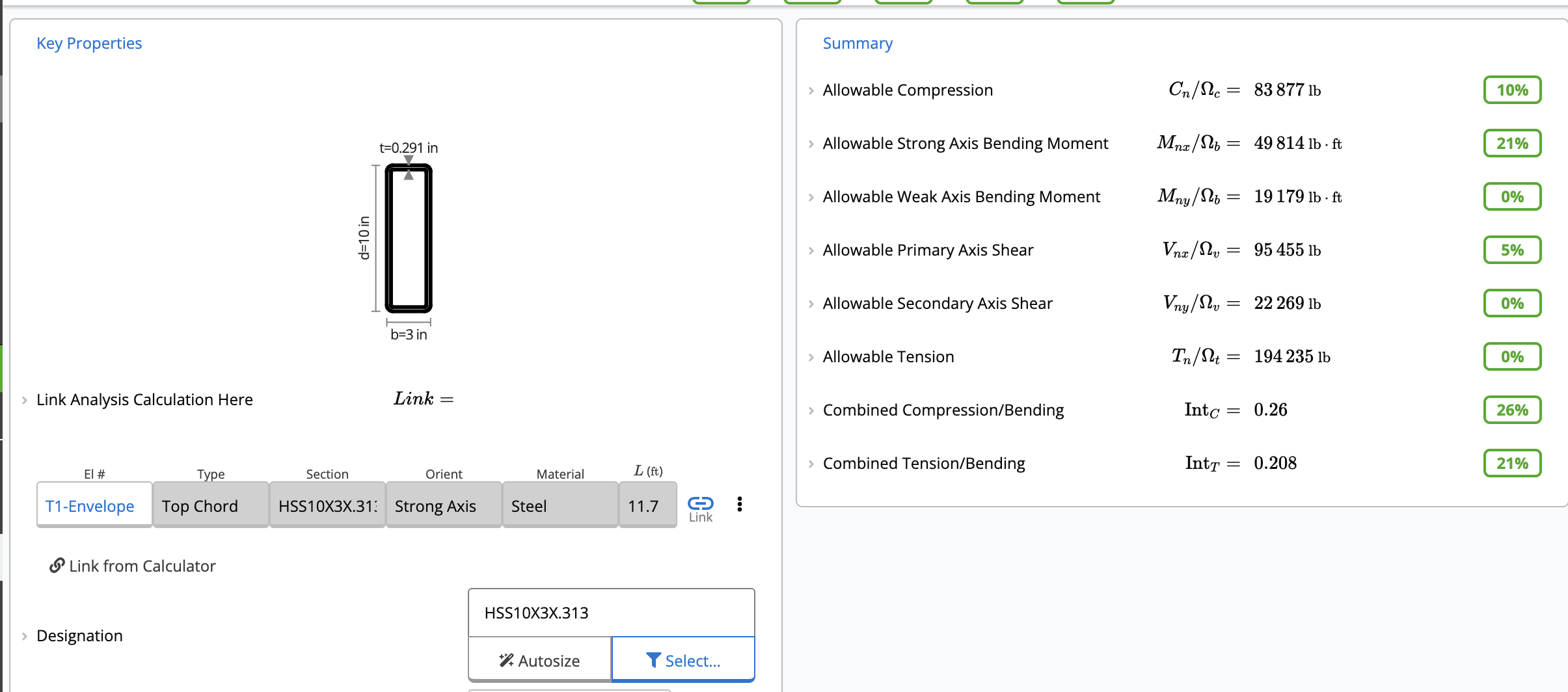
HSS10X3X5/16 passes all code checks.2. Wood Truss Member
Scenario: Checking the Bottom Chord of a Residential Fink Truss.1
Define Geometry
In the Truss Analysis Wizard, go to the Truss Geometry section:
- Set Truss Type to “Fink Roof Truss”.
2
Apply Loads
Scroll to the Distributed Loads on Chords section:
- Enter the load value in Total Distributed Load on Bottom Chord - Vertical (e.g., 50 plf for ceiling plasterboard and insulation).
3
Select Members
Scroll down to the Member Selection section:
- Set Truss Material to “Timber”.
- Go to Bottom Chord Member and select your preliminary section (e.g., “2x6 No.2”).
4
Create Design Calculation
Go to the main menu and create a new Wood Beam (Design Only) calculator.
5
Link Forces
In the new Design calculator, locate the Loads table. Click the Link button (chain icon), select your Truss Analysis calculation as the source, and choose “Bottom Chord”.
6
Check Capacity
The calculator automatically imports the worst-case Axial Tension (T) and Bending Moments (M).Verify the Summary section to ensure the selected timber grade passes the code checks (Utilization < 100%). In this example, it is failing.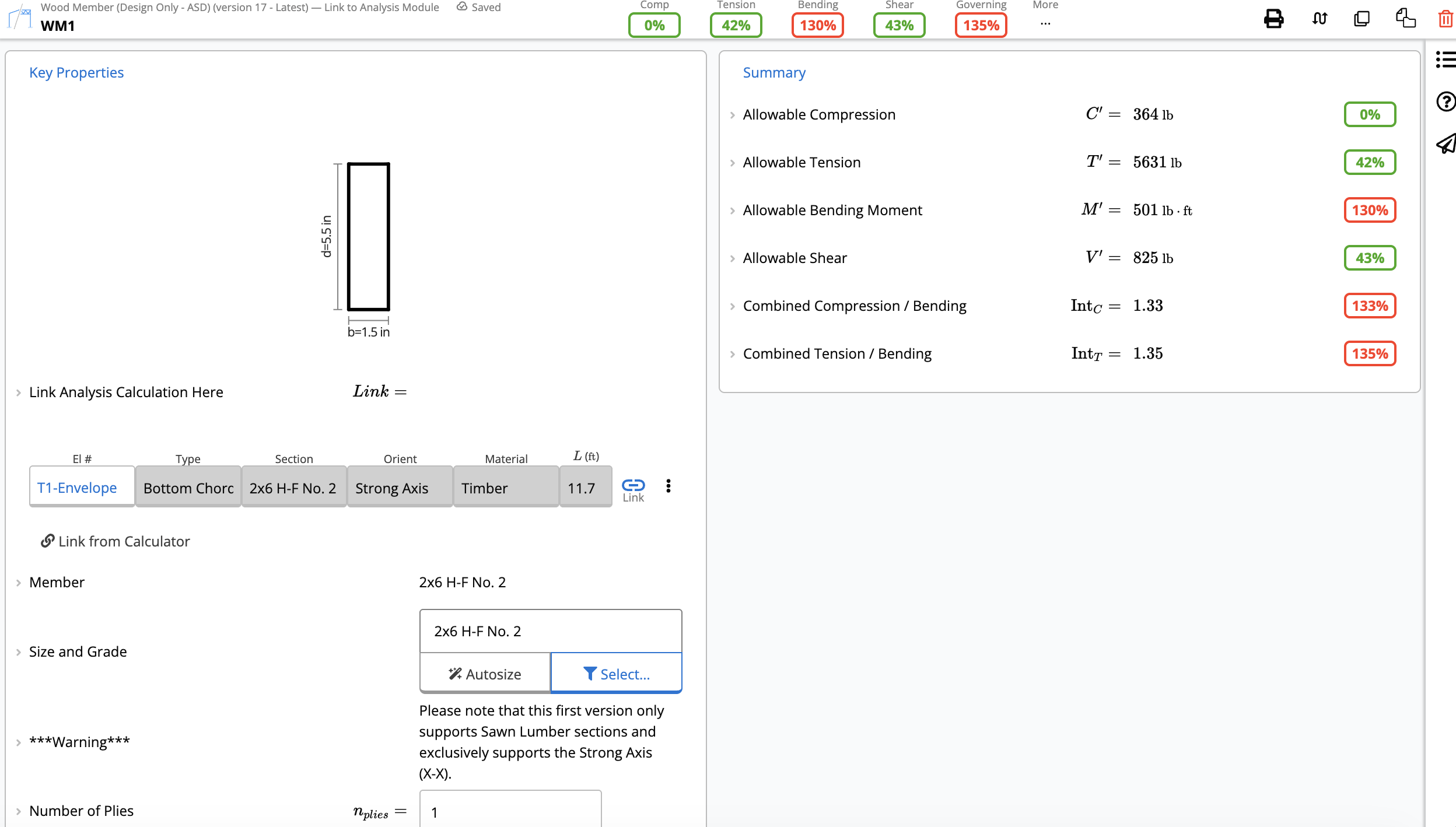
Example B: Portal Frame Analysis
This workflow is practically identical to the truss method explained above. The Portal Frame Analysis Wizard provides results for displacements, moments, and shears, but does not perform code checking on the members themselves.1
Analysis
Configure your Portal Frame (e.g., a flat mono-slope frame). Run the analysis to generate the member forces.
2
Design
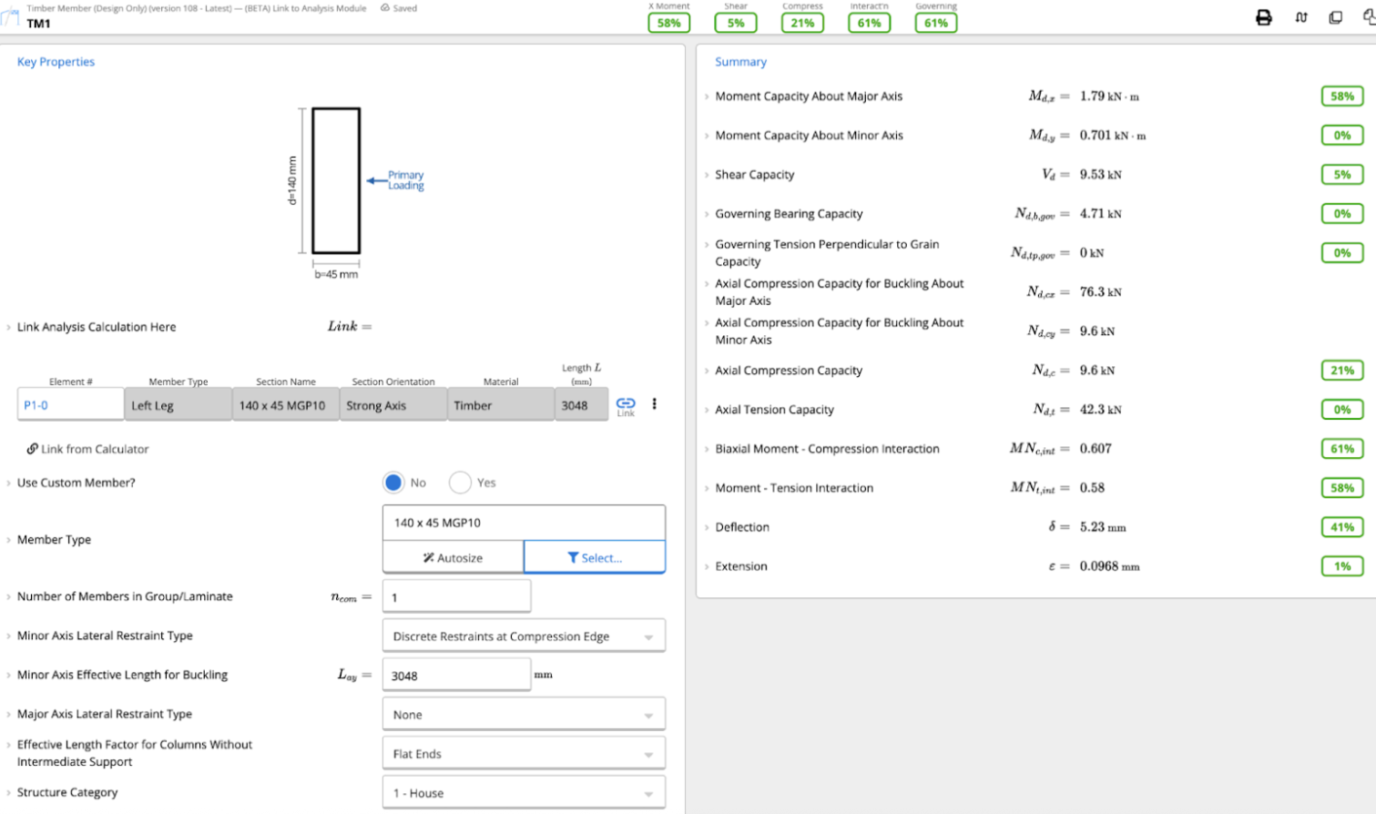
Add a new Design Only calculation. For example, select Timber Member (Design Only).
3
Link
Connect the design sheet to the Portal Frame Analysis and select the specific member you want to check, such as the Left Leg.
4
Capacity Check
The Design calculator will now verify the member against the building code, focusing on:
- Moment Capacity
- Shear Capacity
- Compression Capacity
- Interaction Equations (combined actions)
- Deflection Criteria (customizable in the design module)