1. Entering our key properties
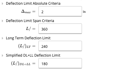
First, we enter the key properties of our beam. No need to touch the beam size yet, we will come back to it later. We enter the total length of 35 feet. Let’s conservatively assume that the beam is only braced at supports. Since we expect we’ll be using a regular wide flange beam, we keep the yield strength at 50 ksi for A992 steel. We use L/360 for deflection limit, which is the limit specified by the International Building Code for normal floors. We also impose an absolute limit of 2 inches on deflection.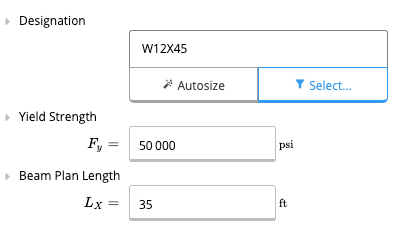
2. Supports
We now enter the supports for the beam. As previously specified, we have two spans, the first 20 feet long and the second 15 feet long. Let’s enter this in our supports table. For the support at the end of the beam, we can also enter “L” for the support location. The support location will then automatically update to the length of the beam.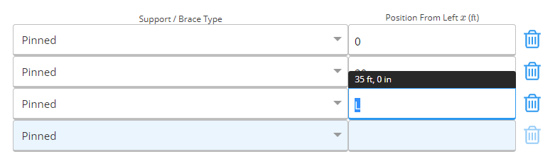
3. Load details
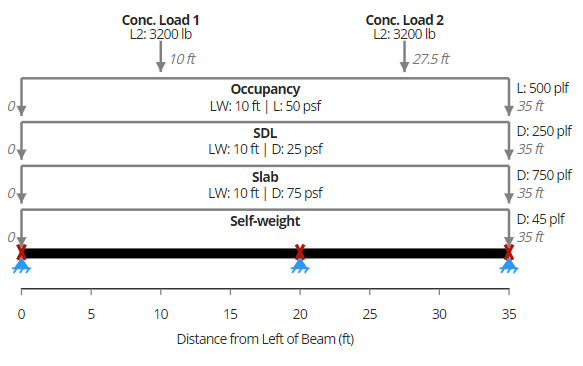
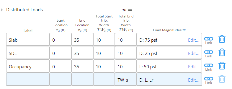
Since our beam is located inside, we don’t have to worry about wind and snow loads. We enter the tributary width as 10 feet - by default entering the tributary width at the start (left end) will also make it equal at the end (right end). Again, since the loads are applied over the length of the beam, we enter the start and end locations as 0 and “L” respectively. For dead load, we have a 6” slab (150 pcf concrete) and a 25 psf super-imposed dead load. We can let Calcs.com calculate the slab dead load in PSF by entering “150 pcf * 6 in”. Calcs.com will handle units for you.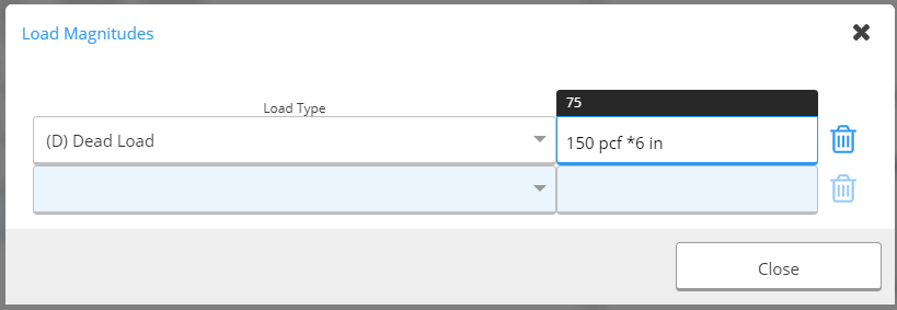
 Now, the IBC also requires that we apply a 3,200 pound concentrated load for office space. This load doesn’t occur at the same time as the uniformly distributed live load. In this case, it’s pretty clear that it won’t govern, but we will still apply for the example. Since the concentrated load doesn’t apply at the same time as the UDL, we’ll apply it in the “Other Loads” section, which allows much more complicated load input.
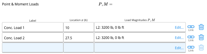 We apply the loads at the midspans of each span (10 ft and 27.5 ft). Note how we enter the load type as “L2” in this case. This means that the internal FEA solver will apply “L” and “L2” separately, and output the envelope of each case.
We can now verify that our loads are all properly placed:
We apply the loads at the midspans of each span (10 ft and 27.5 ft). Note how we enter the load type as “L2” in this case. This means that the internal FEA solver will apply “L” and “L2” separately, and output the envelope of each case.
We can now verify that our loads are all properly placed:
4. Section selection
At this point, we are ready to choose our ideal section. We go back to our Key Properties tab and click on the blue member selector button: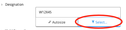 This opens the member selector, a very powerful way to design your members. First, we add the 10” depth restriction and specify a wide-flange section type. Notice that many W10 sections disappear – this is because Calcs.com filters by actual depth and not nominal depth. We are thus left with all AISC sections with a depth less than 10 inches.
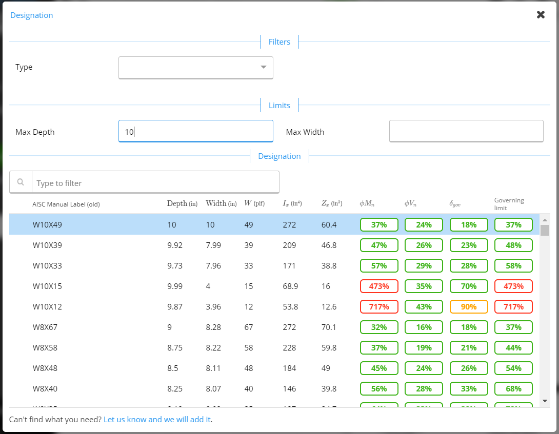 The three right-most columns indicate the utilization for the three governing modes – moment, shear and deflection. Ideally, we want the minimal weight section that will satisfy all three modes. It is then a matter of scrolling to find the best cross-section. Looking through, we find two candidates – a W10x33 or W8x35. We pick a W8x35 section.
That’s it! We’ve now designed our beam!
The three right-most columns indicate the utilization for the three governing modes – moment, shear and deflection. Ideally, we want the minimal weight section that will satisfy all three modes. It is then a matter of scrolling to find the best cross-section. Looking through, we find two candidates – a W10x33 or W8x35. We pick a W8x35 section.
That’s it! We’ve now designed our beam!
5. Summary of results and internal force diagrams
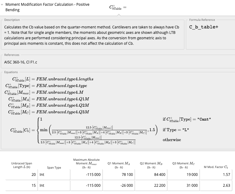
Once we’ve got our beam design, we can quickly glance at relevant values to make sure everything corresponds to what we’d expect. On the right panel is the summary section, where we find things such as the critical moment demand and capacity (taking into account lateral-torsional buckling and C b values), shear, deflections, etc. The dead load deflection is also provided should the beam need to be cambered.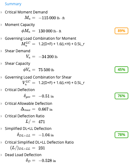 We can also look at the shear, bending and deflection diagrams to make sure they correspond to what we anticipate. As expected, the two concentrated loads don’t do anything for bending since they are so small compared to the UDL. We do see a small tick in the shear force diagrams near the zero-points however, where the concentrated loads produce a slightly higher shear which is reflected in the envelope.
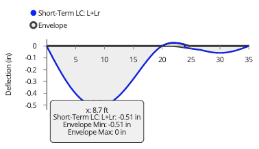
For deflections, we need to switch the load case to reflect a serviceability load case – for here, it is simply “L”. We can scroll down the graph to see exact deflection values at different points. We clearly see that our deflection is much less than the L/360 limit, which is 0.67 inches.
We can also look at the shear, bending and deflection diagrams to make sure they correspond to what we anticipate. As expected, the two concentrated loads don’t do anything for bending since they are so small compared to the UDL. We do see a small tick in the shear force diagrams near the zero-points however, where the concentrated loads produce a slightly higher shear which is reflected in the envelope.
For deflections, we need to switch the load case to reflect a serviceability load case – for here, it is simply “L”. We can scroll down the graph to see exact deflection values at different points. We clearly see that our deflection is much less than the L/360 limit, which is 0.67 inches.
- A more in-depth look
 This concludes our short tutorial on designing a steel beam per AISC 360-16 with Calcs.com.