Scope
The ClearCalcs Portal Frame Analysis calculator allows users to input the geometry of some common portal frame types and specify the load conditions on the truss. It then determines the cumulative load applied, support reactions, bending moment, shear and axial forces, extension and displacement for each individual component of the portal frame. These individual components may then be designed by creating a new “Design Only” calculation and linking it to the portal frame analysis calculation. The sheet has 5 main sections, including the Worked Examples section:- Portal Frame Geometry
2. Member Selection
3. Distributed Loads and Point Loads
4. Worked Examples
5. Designing Components by Linking New Calculators
1 - Portal Frame Geometry
The first section we need to fill in is the Portal Frame Geometry, shown in the figure below.
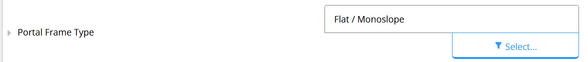
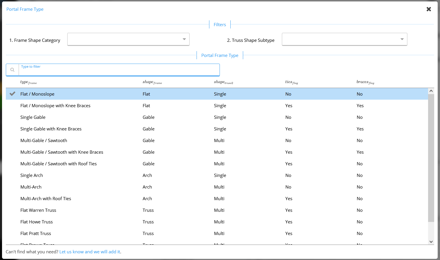
 A - Portal Frame Type
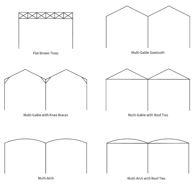
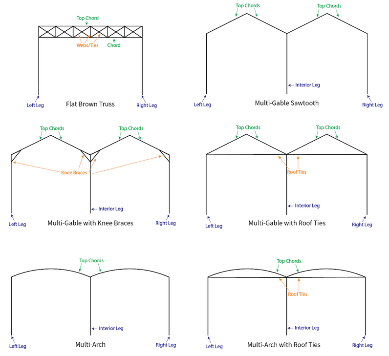
Select your desired portal frame type by clicking the blue ‘Select’ button. ClearCalcs supports the following standard portal frame constructions, plus a custom option if you’re designing for a unique client.
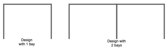
B - Number of Bays
Here we have to input the number of bays/frames used in the design.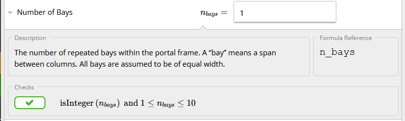 For example:
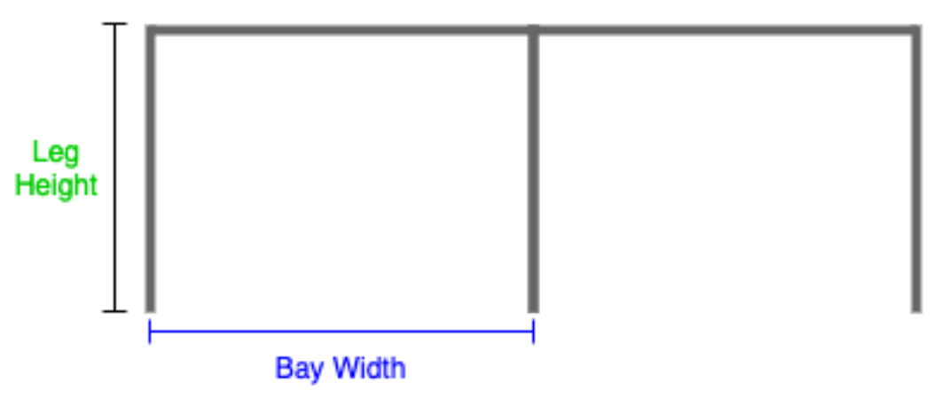
C and F - Bay Width and Leg Height
- Bay Width: the distance between the two legs of the frame

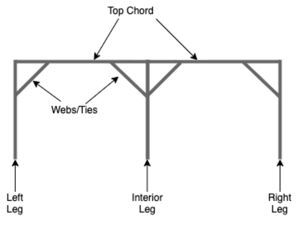
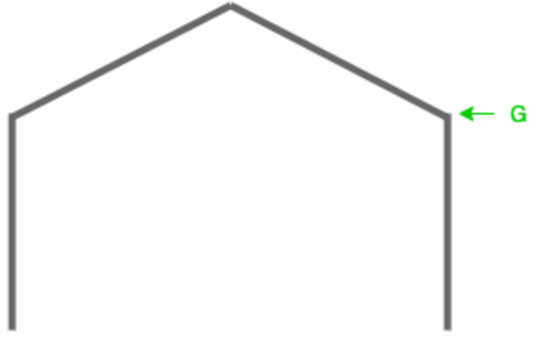
- Leg Height: the height measured from top to bottom, as shown below
D - Default Leg Height
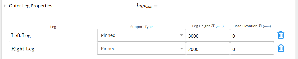
Defines the default leg height when you have multiple legs within your portal frame design and would only like to set the leg height once.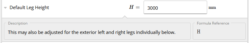 Similar to other default values in ClearCalcs, this can be overridden if your portal frame has different leg heights, as seen in the picture below.
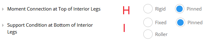
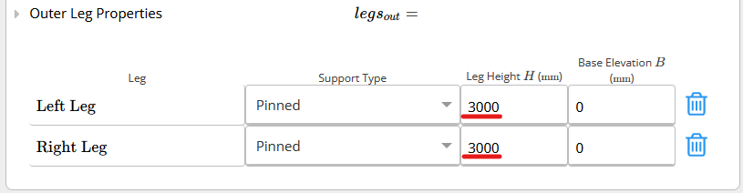
E and I - Support Type
Specify the support type present at the base of each leg.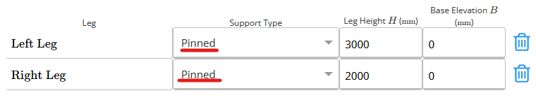
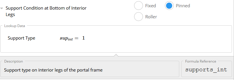 If you want to know more about the difference between Pinned, Fixed and Roller supports, have a look at this article.
G - Base Elevation
Specify the elevation at which the base of each leg is located with respect to the level defined as 0.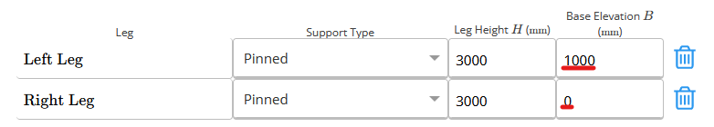
Key Properties Specific to Each Portal Frame Type
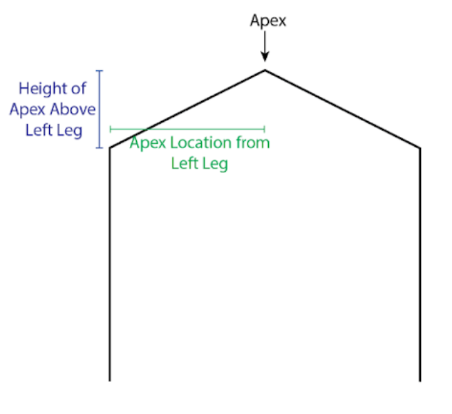
- Apex X Location from Left Leg : The horizontal distance between the left leg and the apex
- Height of Apex Above Left Leg: The vertical distance between the top of the left leg and the apex
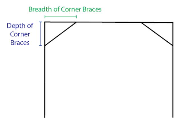
- Depth of Corner Braces: The centreline depth of corner braces below the top of each column.
- Breadth of Corner Braces: The centreline width of the corner brace, measured from the centreline of the column
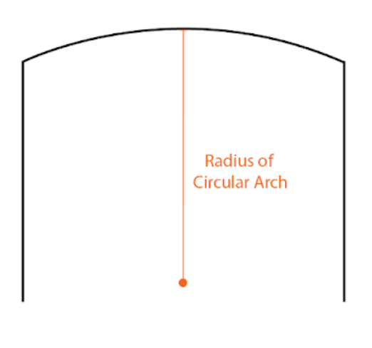
- Radius of Circular Arch: The radius of arch curvature.
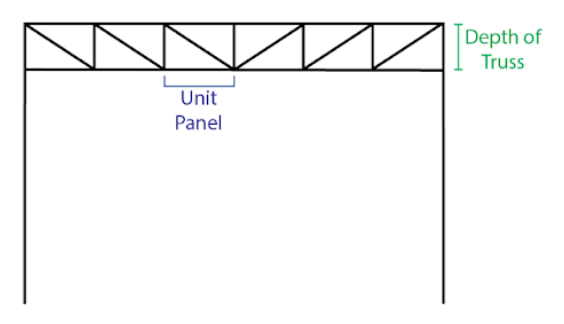
- Depth of Truss: The depth of the truss portion of the portal frame, from the centreline of the top chord to the centreline of the bottom chord.
- Number of Unit Panels in Truss per Bay: A Unit Panel means the smallest subdividable piece of the truss, usually consisting of 2 to 4 web members.
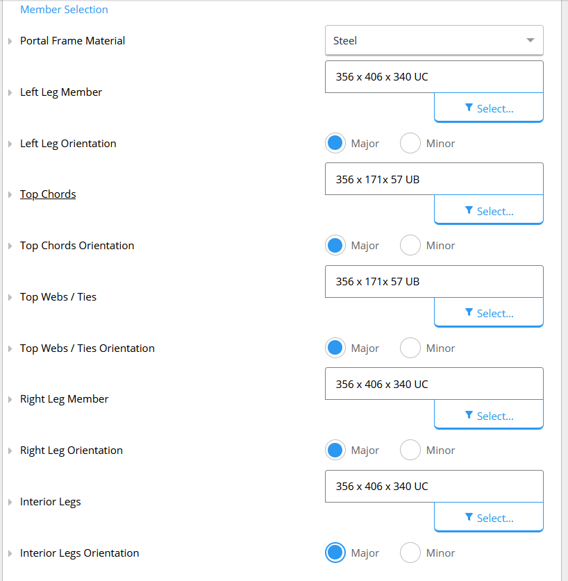
2. Member Selection
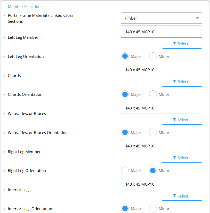
The second section to be filled is the Member Selection, shown in the figure below.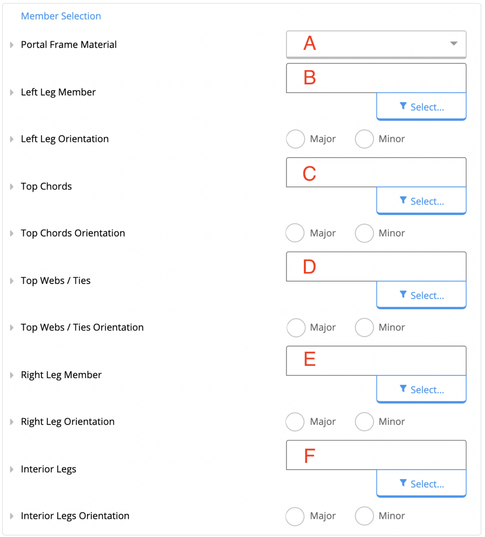 A - Portal Frame Material
In this section, you will choose the portal frame material (i.e., timber/wood, hot rolled steel, CFS, or custom).
Given below is a visual representation of the components to be further specified from B to F.
A - Portal Frame Material
In this section, you will choose the portal frame material (i.e., timber/wood, hot rolled steel, CFS, or custom).
Given below is a visual representation of the components to be further specified from B to F.

 From B to F, the cross-section of the member must be selected from the drop-down menu.
Afterwards, the orientation of each member must be specified whether they are oriented about their major axis (if they bend around the major axis in the portal frame plan), or oriented about the minor axis otherwise.
Note that the orientation changes the bending stiffness of the members.
From B to F, the cross-section of the member must be selected from the drop-down menu.
Afterwards, the orientation of each member must be specified whether they are oriented about their major axis (if they bend around the major axis in the portal frame plan), or oriented about the minor axis otherwise.
Note that the orientation changes the bending stiffness of the members.
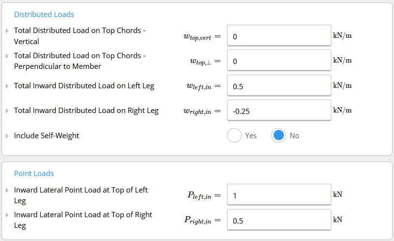
3. Distributed Loads & Point Loads
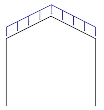
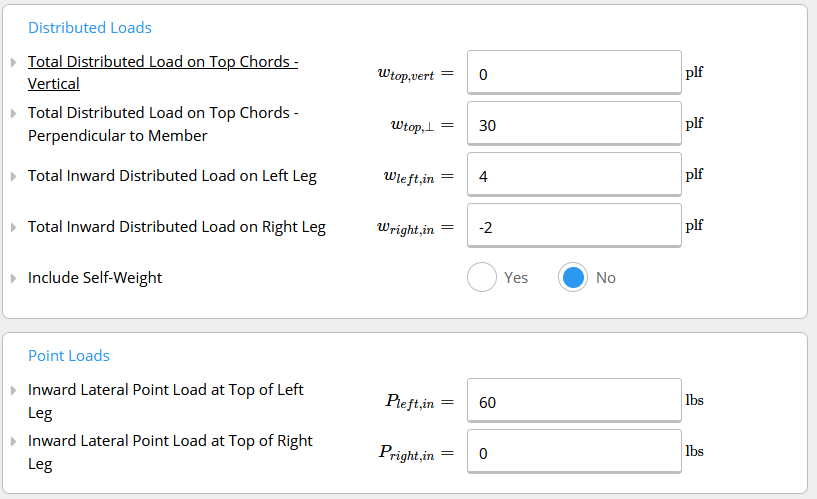
In this section, we can input the distributed and point loads (figure below). A - Total Distributed Load on Top Chord - Vertical
The distributed loads acting on the top chords perpendicular to the ground.
For example, roof and snow loads are gravity loads and will act vertically (or perpendicular to the ground).
A - Total Distributed Load on Top Chord - Vertical
The distributed loads acting on the top chords perpendicular to the ground.
For example, roof and snow loads are gravity loads and will act vertically (or perpendicular to the ground).
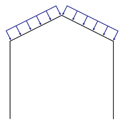
 B - Total Distributed Load on Top Chord - Perpendicular to Member
The distributed loads acting on the top chords perpendicular to the top chord itself.
For example, wind loads will act perpendicular to the member.
B - Total Distributed Load on Top Chord - Perpendicular to Member
The distributed loads acting on the top chords perpendicular to the top chord itself.
For example, wind loads will act perpendicular to the member.
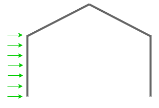
 C - Total Inward Distributed Load on Left Leg
Lateral distributed load acting on the left leg (parallel to the ground).
For example, wind loads acting on the walls of the building.
C - Total Inward Distributed Load on Left Leg
Lateral distributed load acting on the left leg (parallel to the ground).
For example, wind loads acting on the walls of the building.
 D - Total Inward Distributed Load on Right Leg
Lateral distributed load acting on the right leg (parallel to the ground).
D - Total Inward Distributed Load on Right Leg
Lateral distributed load acting on the right leg (parallel to the ground).
 E - Include self-weight
Choose whether or not to include the weight of the portal frame in the calculations.
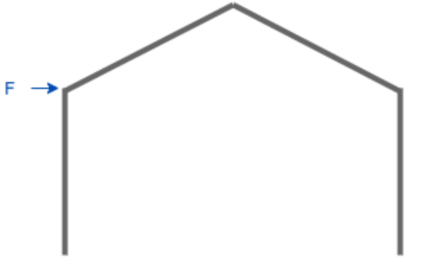
F - Inward Lateral Point Load at the Top of Left Leg
Point load acting on the top of the right leg (parallel to the ground).
E - Include self-weight
Choose whether or not to include the weight of the portal frame in the calculations.
F - Inward Lateral Point Load at the Top of Left Leg
Point load acting on the top of the right leg (parallel to the ground).
 G - Inward Lateral Point Load at the Top of Right Leg
Point load acting on the top of the left leg (parallel to the ground)
G - Inward Lateral Point Load at the Top of Right Leg
Point load acting on the top of the left leg (parallel to the ground)
4. Worked Examples
4.1 Example 1: Flat Portal Frame
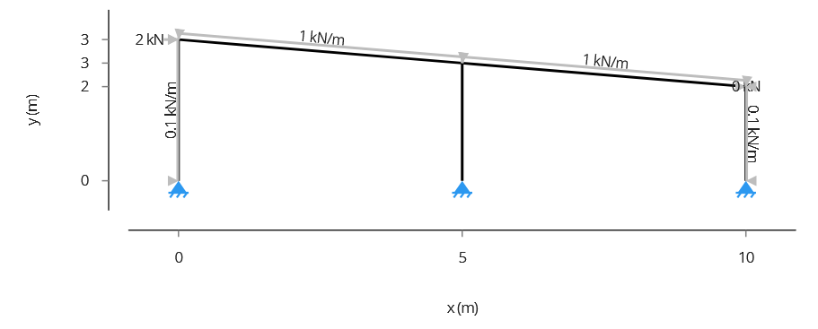
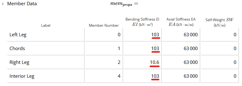
In this Example 1, we will analyse a Flat Portal Frame made of steel, with 2 bays with a spacing of 5 m. The height of the right leg is 3 m, the interior leg is 2.5 m and the left leg is 2 m. The image below shows the frame geometry and the loads. The frame material is steel, and the following sections were selected, oriented on the major axis, which means that the elements bend around the major axis. Note that the bending stiffness (EI) changes when the orientation of the element is changed.
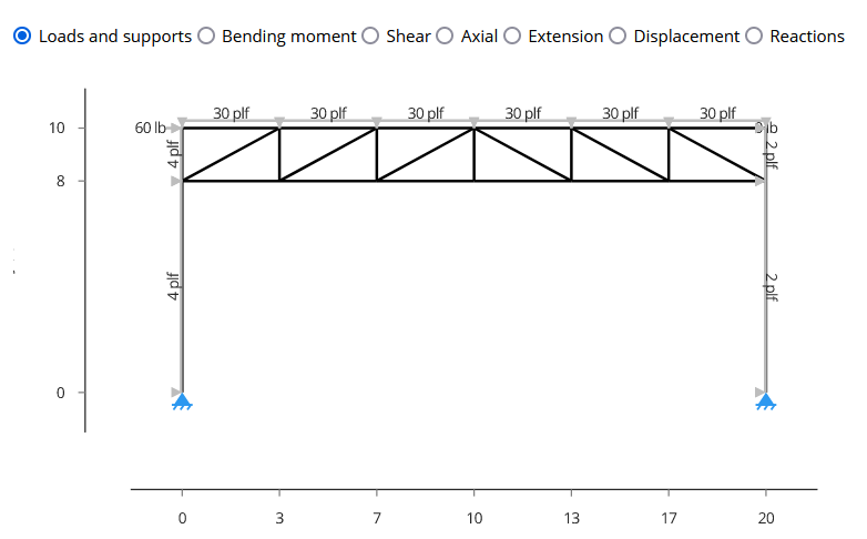
 Uniformly distributed loads and point loads are applied according to the figure below. For the top chords, positive loads are downwards. For the left and right legs, positive loads are to the right and left, respectively. The point loads are positive in the right direction.
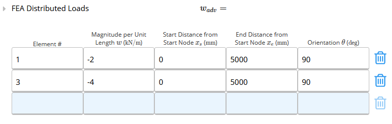
 The Advanced Loads (by Element Number) section should be used when the loads are not the same for all the elements or it applies partially along the length of the element. A 2 kN/m loading is applied to Element #1, and 4 kN/m to Element #3. The load sign is negative and the orientation is 90 degrees. The start and end distances are relative to the start node of the element.
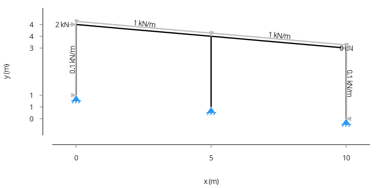
 To verify if the loads are applied correctly, check the diagram in the “Summary” tab, selecting “Loads and supports”. The arrow indicates the direction where the load is applied.
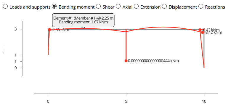
 Also in the Summary tab, you can check the bending moment, shear forces, and axial forces diagrams. Note that the bending moment diagram is drawn on the compression side of the element. You can hover on the diagram to see the values at any point of the frame.
 It is possible to check the extension of the members and also the deflected shape through Extension and Displacement, respectively. The reactions can be visualised as well.

4.2 Example 2: Flat Howe Truss
In this Example 2, we will analyse a Flat Howe Truss made of timber, the geometry is shown below. All the elements are 2x6 H-F No.2, oriented on major axis. The figure below shows the Portal Frame to be analysed. Uniformly distributed loads and point loads are applied according to the figure below. Just as Example 1, check the orientation of the loads.
 Check the axial force diagram. Positive values indicate compression and negative tension.
 The axial forces can also be checked on the Overall Results by Member Type table, through the P+ and P- columns.
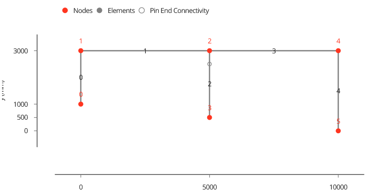
 You can check detailed information for all members by looking at the Overall Results by Element Number table. Check the numbering of the elements in the diagram under the Individual Node & Element Results tab.

 When checking the extension of the member, positive values indicate shrinking and negative stretching.
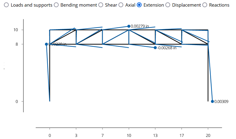 Through the displacement diagram, it is possible to check that the maximum displacement is 0.643 in.
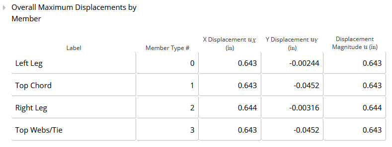
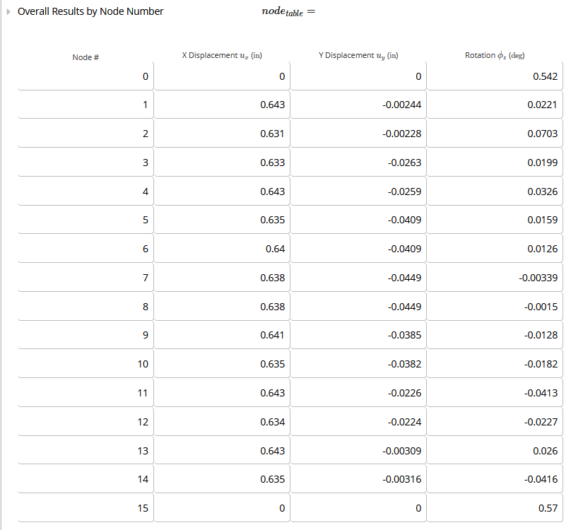
 This maximum displacement can also be obtained through the table Overall Maximum Displacements by Member or Overall Results by Node Number.
5. Designing Components by Linking New Calculators
Typically, once a portal frame is analysed, the components will also need to be designed. This may be done in ClearCalcs by the following procedure:- Select “Add New Calculation” in the left sidebar
- Add a “Design Only” calculator for the appropriate material (for example, “Timber Member (Design Only)”)
- Next to the loads table in this new calculator, click on Link
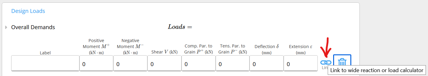
- In the modal that pops up, select the portal frame analysis calculation, and then the component of the truss you wish to design (for example, “Top Chord”)
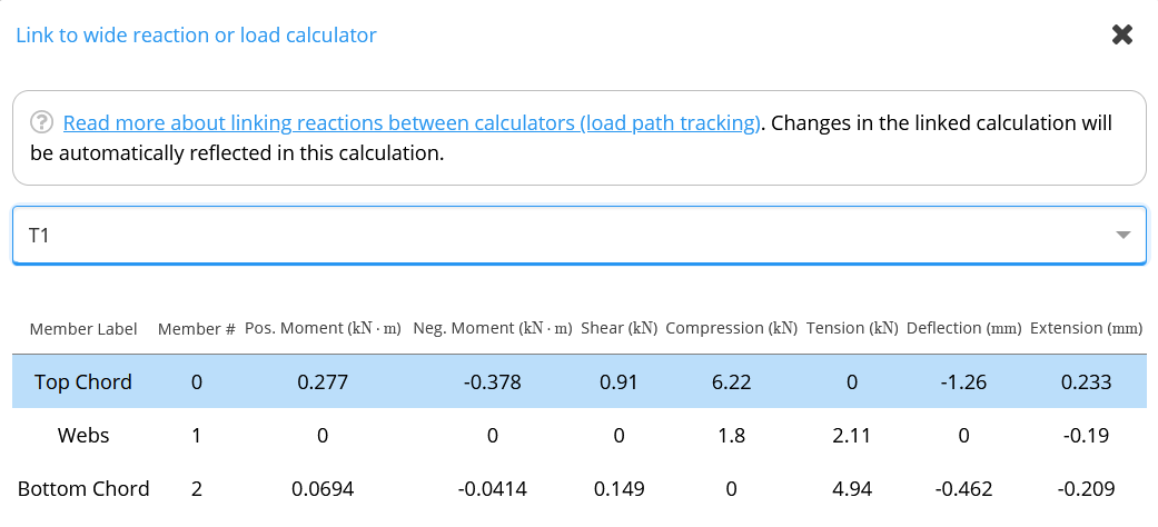
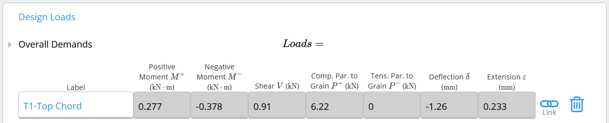
- Complete the rest of the design as normal, referring to the help documentation for the specific material. For additional assistance on beam design, follow this link (US, Australia, Europe) for timber beam, this link (US, Australia, Europe) for steel beam, and this link (US, Australia) for cold-formed steel beam design.