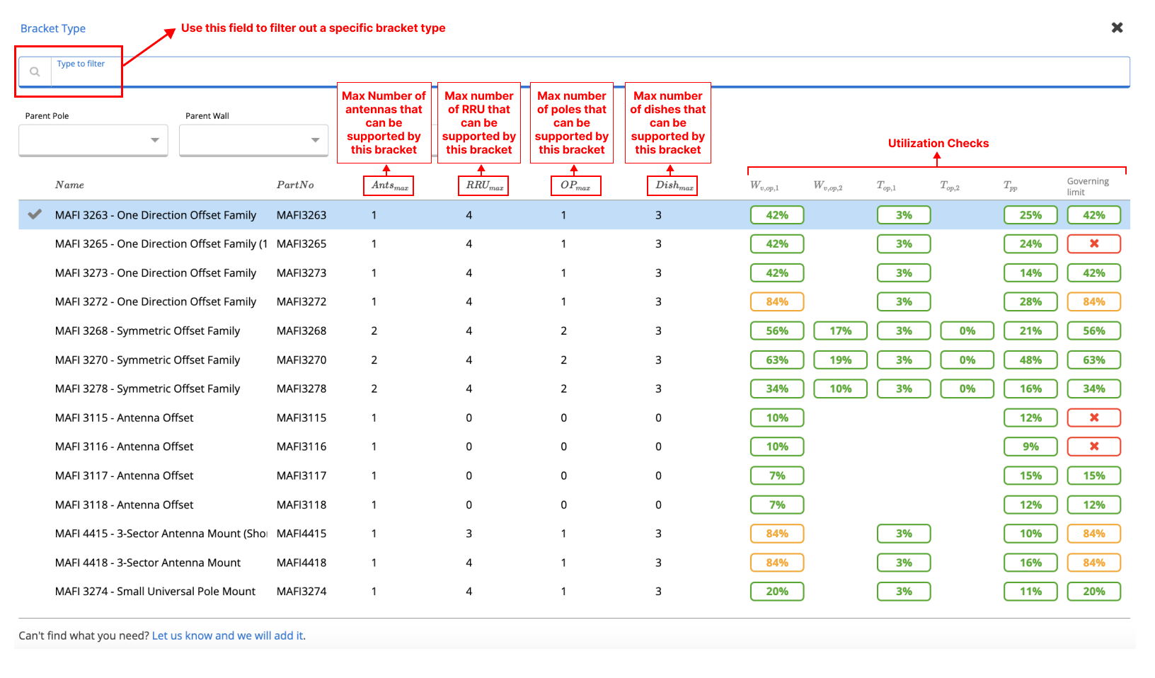
 Figure 6. Bracket Type Selector
The orientation and the direction of the bracket are two other important inputs that help with the calculation of the forces on the brackets, Therefore careful consideration shall be given to these values. Figure 7 demonstrates the orientation of an offset bracket when the bracket is located 100 degrees clockwise from True North. Note If using a symmetric bracket, consider the Antenna 1 arm as the bracket orientation vector.
Figure 6. Bracket Type Selector
The orientation and the direction of the bracket are two other important inputs that help with the calculation of the forces on the brackets, Therefore careful consideration shall be given to these values. Figure 7 demonstrates the orientation of an offset bracket when the bracket is located 100 degrees clockwise from True North. Note If using a symmetric bracket, consider the Antenna 1 arm as the bracket orientation vector.
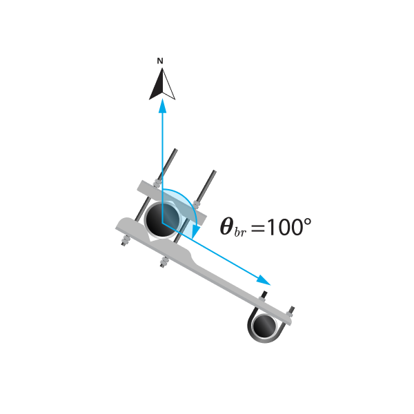 Figure 7. Orientation of Bracket
The direction of the brackets could be a tricky concept to comprehend. The user has to imagine the direction of the offset pole as it is rotating anticlockwise (A) or clockwise (B) around the parent pole. Figure 8 demonstrates an example of the direction of the bracket. Note that this input plays a very critical role in determining the coordinates of the antennas and equipment.
Figure 7. Orientation of Bracket
The direction of the brackets could be a tricky concept to comprehend. The user has to imagine the direction of the offset pole as it is rotating anticlockwise (A) or clockwise (B) around the parent pole. Figure 8 demonstrates an example of the direction of the bracket. Note that this input plays a very critical role in determining the coordinates of the antennas and equipment.
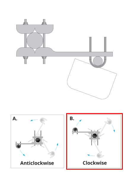 Figure. 8. Example Direction of Bracekt
The Offset distance of poles is also important information that should be carefully selected. As seen in Figure 9 the offset distance is the horizontal distance between the parent pole and the offset pole and it could vary depending on the location of the hook which is holding the offset pole.
Figure. 8. Example Direction of Bracekt
The Offset distance of poles is also important information that should be carefully selected. As seen in Figure 9 the offset distance is the horizontal distance between the parent pole and the offset pole and it could vary depending on the location of the hook which is holding the offset pole.
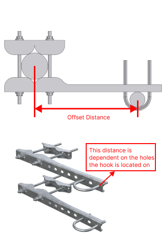 Figure 9. Offset Distance of Offset Bracket
Bracket-on-a-Bracket
The bracket-on-a-bracket feature of the bracket checker allows the user to design an arrangement with a symmetric bracket being held by an inner bracket as seen in Figure 11.
Figure 9. Offset Distance of Offset Bracket
Bracket-on-a-Bracket
The bracket-on-a-bracket feature of the bracket checker allows the user to design an arrangement with a symmetric bracket being held by an inner bracket as seen in Figure 11.
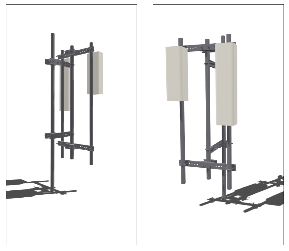 Figure 11. Example Bracket-on-a-Bracket System
To activate this feature the user has to select a symmetrical bracket in the bracket selector. Once a symmetrical bracket is selected this toggle shown in Figure 12 is prompted to the user asking them whether they would like to design a bracket-on-a-bracket system. As the bracket-on-a-bracket arrangement is selected, another set of bracket properties inputs is visible to the user that will define the properties of the inner bracket.
Figure 11. Example Bracket-on-a-Bracket System
To activate this feature the user has to select a symmetrical bracket in the bracket selector. Once a symmetrical bracket is selected this toggle shown in Figure 12 is prompted to the user asking them whether they would like to design a bracket-on-a-bracket system. As the bracket-on-a-bracket arrangement is selected, another set of bracket properties inputs is visible to the user that will define the properties of the inner bracket.
 Figure 12. Bracket-on-a-Bracket Toggle