

When to use this calculator
- Column spacing is tight enough that individual footings would overlap or encroach on a property line or setback.
- Two columns must share one concrete pad and you need eccentric bearing, dual punching checks, and negative bending between columns in one sheet.
- A single column near a boundary is outside this calculator’s scope. Use the spread footing calculator instead.
Full assumptions and limitations are listed in the Sheet Details tab within the calculator.
Inputs
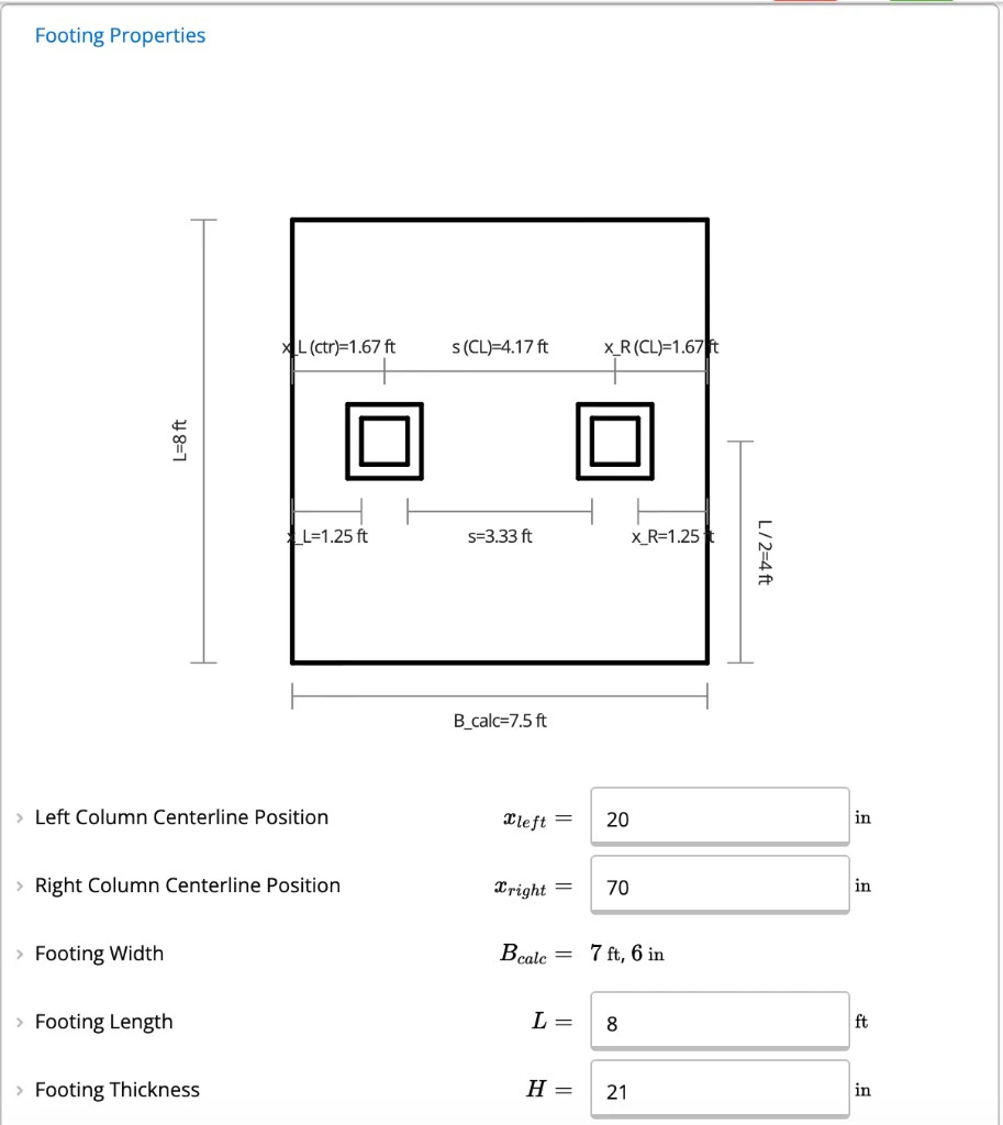
Work through the input sections in order. Geometry and loads drive everything downstream.Footing Properties
Plan dimensions, thickness, concrete strength, and column centerline locations feed bearing eccentricity, critical bending sections, and available development length in the calculations below.- Left Column Centerline Position and Right Column Centerline Position: measured from the left footing edge. These positions appear in the plan diagram and affect bearing, development length, and shear critical sections.
- Footing Length, Footing Width, and Footing Thickness: length and column positions feed bearing and negative bending between columns. Thickness feeds effective depth (d) used in one-way shear, punching shear, and flexural capacity. This calculator has no shear reinforcement inputs.
Left and Right Column Properties
Each column has its own properties section. Column Width and Column Length define the column face for flexure and the d/2 punching perimeter. For steel columns, also enter base plate dimensions; the calculator computes Effective Bearing Width and Effective Bearing Length for the column-footing interface check.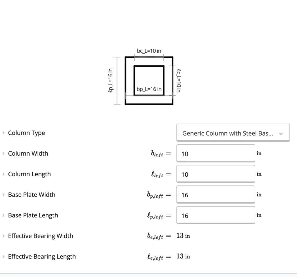
Soil Properties
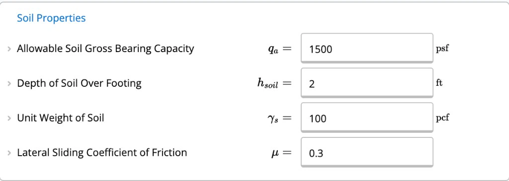
Soil inputs set service bearing checks and stability against overturning and sliding.- Allowable Soil Gross Bearing Capacity: entered from your geotechnical report. See Understanding Gross vs Net Soil Bearing Pressure for how to enter geotechnical values in Calcs.com.
- Depth of Soil Over Footing: used in self-weight, overturning, and uplift calculations in Bearing & Overturning Factor of Safety and Uplift Safety Factor.
Bottom Reinforcement
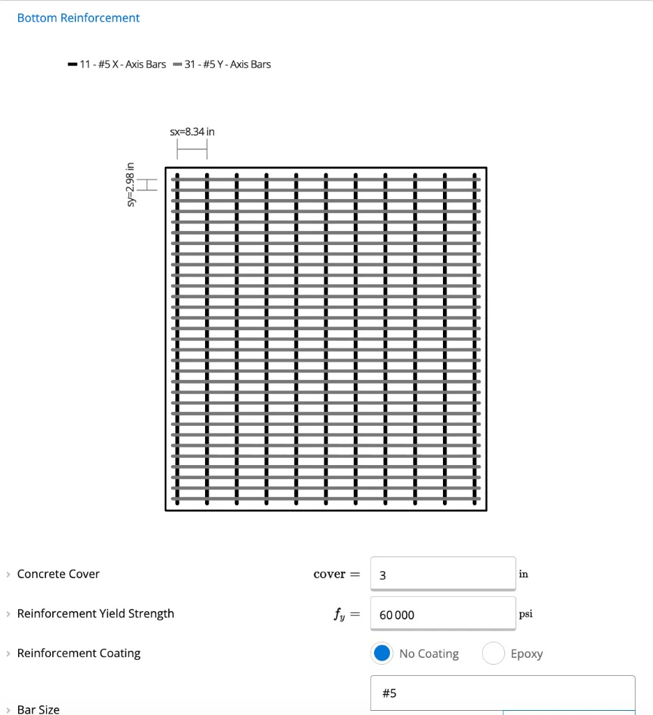
Bottom reinforcement is checked for positive bending at each column face. Enter bar count in each plan direction:- Bar Count - X-Axis Bending
- Bar Count - Y-Axis Bending
Top Reinforcement
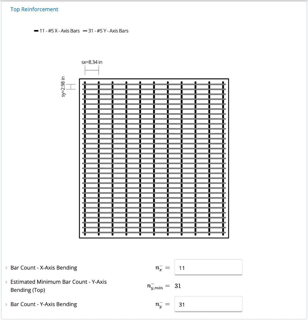
Top reinforcement is checked for negative bending between the columns. This is the main difference from a typical single-column spread footing in this calculator. Enter bar count in each direction:- Bar Count - X-Axis Bending
- Bar Count - Y-Axis Bending
Bearing Dowels
For concrete columns, specify Dowel Size, Number of Dowels, and Dowel Yield Strength. Dowels transfer load at the column-footing interface and are checked for development length in the interface capacity sections.Applied Loads
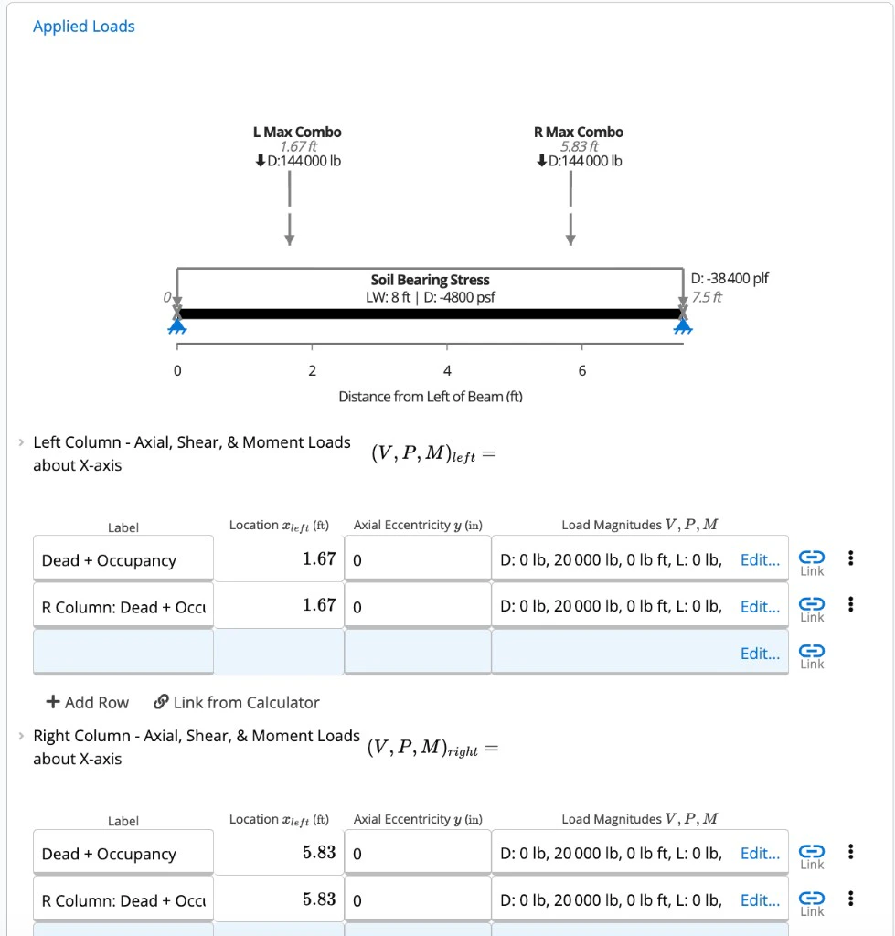
Enter concentrated loads at each column in the load tables:- Left Column - Axial, Shear, & Moment Loads about X-axis
- Right Column - Axial, Shear, & Moment Loads about X-axis
- Left Column - Shear & Moment Loads about Y-axis
- Right Column - Shear & Moment Loads about Y-axis
Calculations
After inputs are set, the calculator builds ASD service checks and LRFD strength checks. Open Detailed view to see intermediate steps and ACI 318-19 clause references for each section below.Design Criteria and Load Combinations
Design Criteria pulls the load combination code from project defaults (IBC 2024 / ASCE 7-22) and sets minimum factors of safety for overturning, sliding, and uplift. Total Loads rolls up unfactored column loads, self-weight, and soil overburden. ASD Load Combinations and LRFD Load Combinations expand service and strength combinations for the combined footing and for each column separately. Strength combinations govern flexure, shear, punching, and interface checks.Bearing and Stability
Bearing & Overturning Factor of Safety checks gross soil bearing at service loads using the eccentric resultant of both column loads. When Stability shows partial or full tension, the effective bearing area is reduced. Summary rows Soil Gross Bearing Stress and Allowable Gross Soil Bearing Stress report the governing result. Column positions and Footing Length are the geometry inputs that affect eccentricity. Sliding Factor of Safety and Uplift Safety Factor compare resisting forces (friction and self-weight) to lateral and uplift demands across ASD combinations.Footing Demands
Footing Demands - Concrete Bending, Bearing, & Shear assembles the beam model along the footing length. It reports ultimate bearing pressure, load eccentricity, and the factored shear and moment diagrams used for flexural and shear checks. The governing load combination for graphed results is selected automatically.Flexural Capacity
Positive moment at column faces is resisted by bottom bars; negative moment between columns is resisted by top bars.- Flexural Capacity - X-Axis and Flexural Capacity - Y-Axis (ACI 318-19, Cl. 22.2): positive bending at each column face.
- Negative Bending Flexural Capacity - X-Axis and Negative Bending Flexural Capacity - Y-Axis (ACI 318-19, Cl. 22.2): negative bending between the columns.
One-Way Shear (ACI 318-19, Cl. 22.5)
One-way shear is evaluated at a critical section d from each column face. The calculator checks the left and right columns independently, and checks X-axis and Y-axis bending within each column. Open Left Column - One-Way Shear Capacity and Right Column - One-Way Shear Capacity in Detailed view to see each check individually. This calculator has no shear reinforcement inputs. Footing Thickness and Concrete Strength in Footing Properties feed one-way shear capacity. The size factor λs is taken as 1.0 for footings per Cl. 13.2.6.2. When plain concrete governs or bar development is inadequate, Resistance Factor in Shear (φv) drops from 0.75 to 0.60. That reduction applies to both one-way and two-way shear capacities.Two-Way (Punching) Shear (ACI 318-19, Cl. 22.6)
Punching shear is checked separately at each column using a critical perimeter at d/2 from the column face. Open Left Column - Two-way / Punching Shear Capacity and Right Column - Two-way / Punching Shear Capacity for per-column demand and capacity. By default, punching demand does not include upward soil pressure under the critical shear perimeter. Summary rows Two-Way Shear Demand and Two-Way Shear Capacity report the governing column. Footing Thickness and Concrete Strength feed the punching capacity calculation.Reinforcement Development (ACI 318-19, Cl. 25.4)
Development of Bottom Reinforcement and Development of Top Reinforcement check whether bars can develop over the available length at each column face and at mid-span. Development length is checked separately for X-axis and Y-axis reinforcement. If required development exceeds available length, the calculator tests plain concrete automatically. The calculator applies the excess-reinforcement-area factor (ACI 318-19, Cl. 25.4.10). Changing Bar Count updates both required and provided steel area in the development length calculation.Column-Footing Interface (ACI 318-19, Cl. 22.8)
Concrete bearing at the column-footing interface is checked at each column separately in Left Column - Column-Footing Interface Capacity and Right Column - Column-Footing Interface Capacity. For each interface, the calculator compares the column loaded area to a spread resisting area assuming load spread at a 2:1 slope (63° from vertical) through the footing. If dowel development length exceeds the available distance, the interface section flags it. The Left Column - Column-Footing Interface Capacity and Right Column - Column-Footing Interface Capacity sections show dowel development checks. Inputs that feed this check include Footing Thickness, Dowel Size, and Number of Dowels in Bearing Dowels.Results
The Summary panel on the right collects governing pass/fail outcomes. Switch to Detailed using the toggle at the top of the calculator to drill into any check listed below.Reading the Summary
The Summary panel shows pass/fail for governing checks at a glance. Green badges indicate passing utilization; red badges flag a governing failure.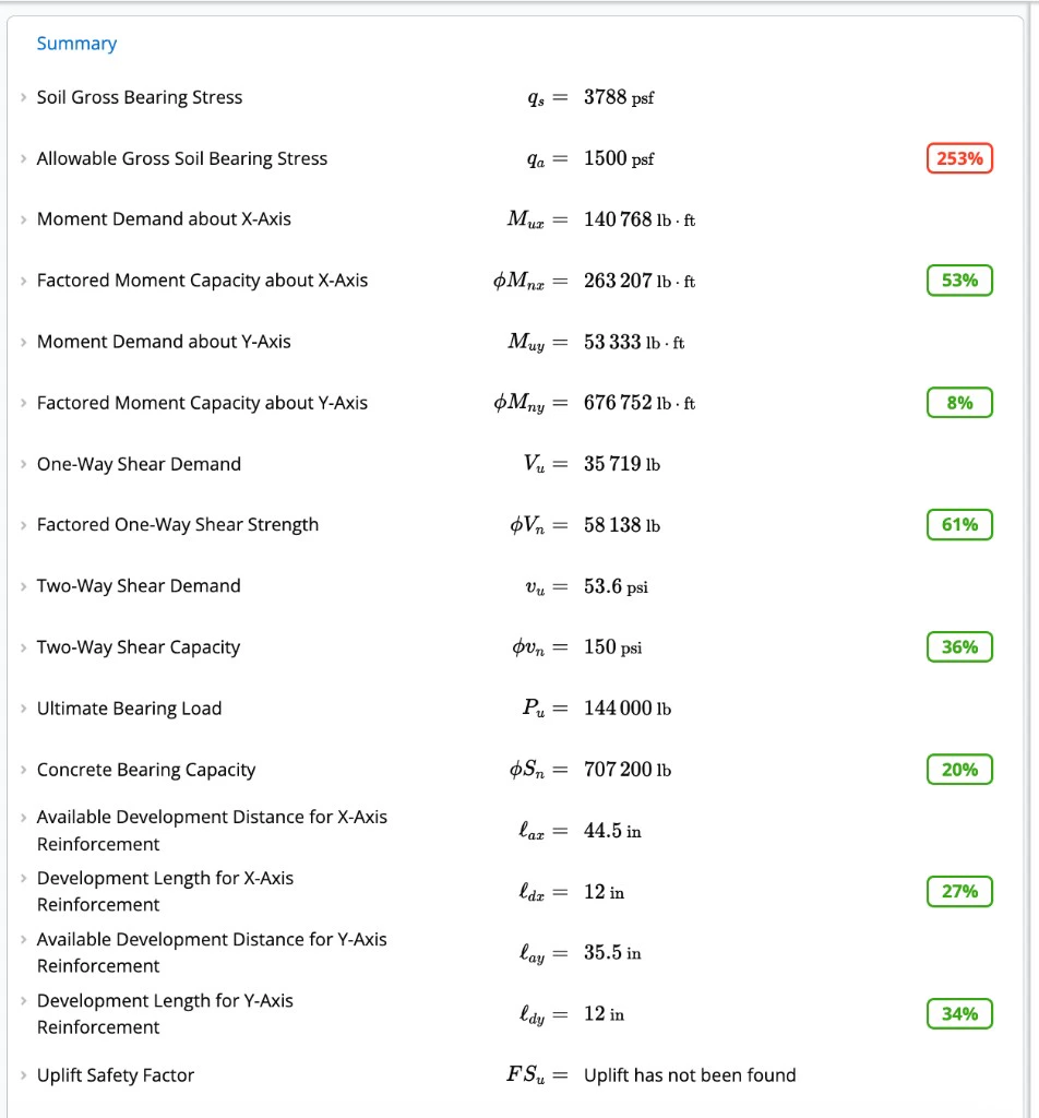
- Soil Gross Bearing Stress vs Allowable Gross Soil Bearing Stress
- Moment Demand about X-Axis / Factored Moment Capacity about X-Axis and the matching Y-axis rows
- One-Way Shear Demand / Factored One-Way Shear Strength
- Two-Way Shear Demand / Two-Way Shear Capacity
- Ultimate Bearing Load / Concrete Bearing Capacity
- Available Development Distance for X-Axis Reinforcement / Development Length for X-Axis Reinforcement and the matching Y-axis rows
- Design Passes as Plain Concrete (X-Axis)? and the Y-axis equivalent
- Sliding Factor of Safety - X-Axis, Sliding Factor of Safety - Y-Axis, Uplift Safety Factor, and Stability
Reading the Diagrams
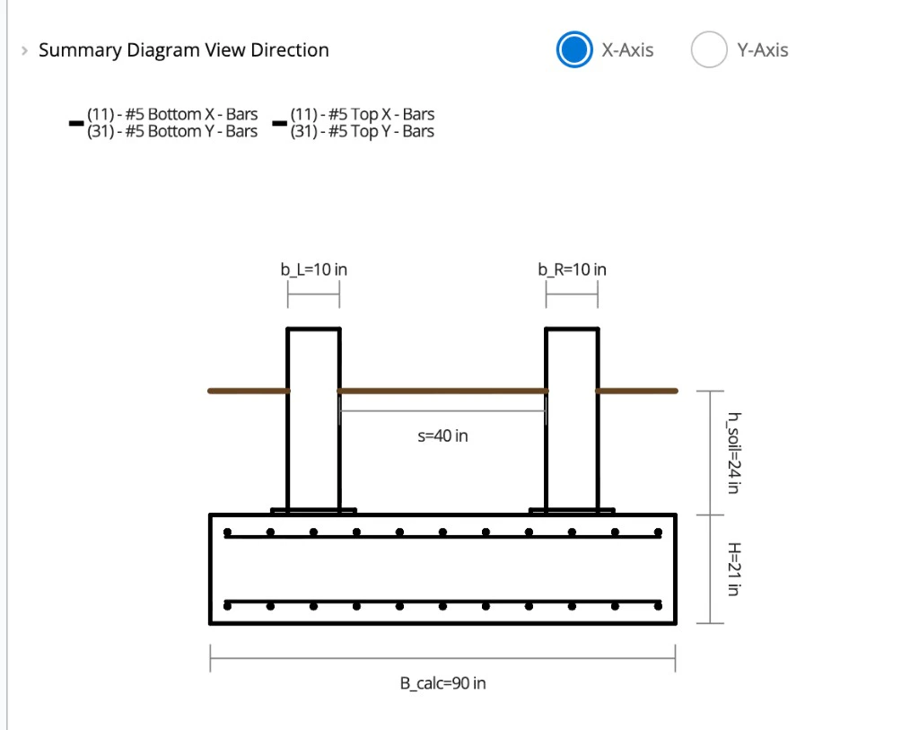
The Summary Diagram View Direction lookup selects which elevation the summary diagrams show:- X-Axis: elevation along the footing length (the direction between the two columns).
- Y-Axis: elevation along the footing width (perpendicular to the column line).
Geometry and reinforcement
Geometry and reinforcement
- Bottom Reinforcement Depth & Spacing
- Top Reinforcement Depth & Spacing
Loading, bearing, and strength checks
Loading, bearing, and strength checks
- Applied Loads
- Total Loads
- Bearing & Overturning Factor of Safety
- Footing Demands - Concrete Bending, Bearing, & Shear
- Flexural Capacity - X-Axis and Y-Axis (ACI 318-19, Cl. 22.2)
- Negative Bending Flexural Capacity - X-Axis and Y-Axis (ACI 318-19, Cl. 22.2)
- One-Way Shear Capacity (ACI 318-19, Cl. 22.5)
- Left and Right Column - Two-way / Punching Shear Capacity (ACI 318-19, Cl. 22.6)
Development and column-footing interface
Development and column-footing interface
- Development of Bottom and Top Reinforcement (ACI 318-19, Cl. 25.4)
- Left and Right Column - Column-Footing Interface Capacity (ACI 318-19, Cl. 22.8)
Troubleshooting
Inputs flagged in red
Inputs flagged in red
Check the validation message next to the field. Common causes are geometry conflicts, incompatible column positions, or load combinations that produce unexpected demands.
Plain concrete fallback appeared
Plain concrete fallback appeared
Reinforcement could not be developed over the available length. Check Development Length for X-Axis Reinforcement and the Y-axis equivalent in Summary, then review Bar Count, Footing Thickness, and Ends of Reinforcement inputs to see what changed when the plain concrete fallback triggered.
One check is governing the design
One check is governing the design
Open that check in Detailed view to see which inputs feed the calculation. Summary rows link to the governing section. Use the input list above to find the corresponding fields in the sheet.
Related calculators and articles
- How to Design a Spread Footing to ACI 318-14: shared bearing, flexure, and shear concepts for single-column footings
- Understanding Gross vs Net Soil Bearing Pressure: how to enter allowable bearing capacity from a geotechnical report
- Spread Footing to ACI 318-14 — Validation Examples: similar check methodology with worked comparisons
- Footings Under Biaxial Bending: background on eccentric bearing and moment effects