

Scope
Our portal frame sheets are designed to perform quick 2D analysis on a variety of portal frame types. Our steel section library is included to calculate all design actions on the structure according to the exact loads as applied by the designer. These sheets do not apply load factors nor calculate the design and strength capacities of structural members - to complete your design, you will need to link to one of our Member (Design Only) calculators and pull in the relevant values for shear, moment, and deflection.Types of Portal Frames in Calcs.com and Key Inputs
Our portal frame calculators are available for a variety of common and custom portal frame types you can choose from a simple drop down. They are designed to allow for quick FEA analysis of a 2D portal frame without needing to waste time modelling nodes and members in a full-fledged analysis software. Depending on the type of portal frame you select in the dropdown (for example, flat/monoslope), the diagram on the right hand side will change, as will the inputs required (for example, a gable roof requires an apex height in addition to leg height).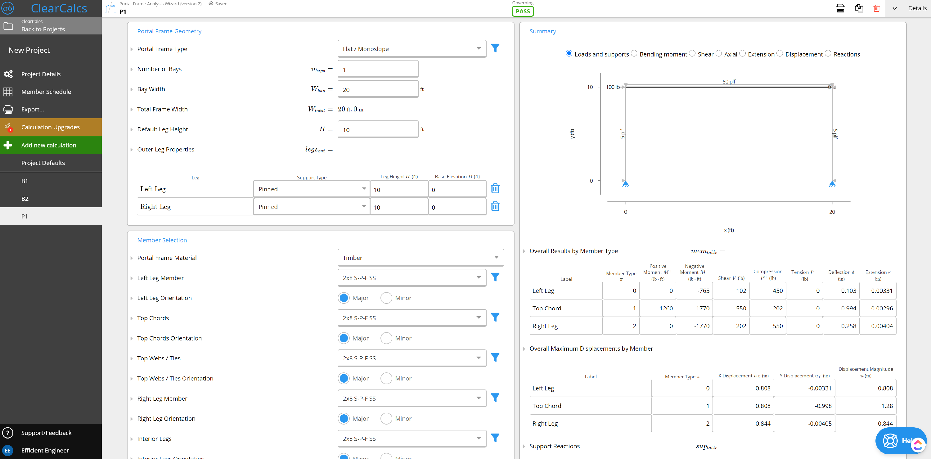 General Notes
- The main purpose of these sheets is to determine the shear, moment, and deflection of the portal frame.
- Supports can be specified as pinned or fixed, and each member can be specified independently
- The geometry of the portal frame is pre-specified to save the time otherwise spent specifying nodes and fixicities. Simply specify a height and width, or additional custom fields (ex. number of bays) based on your needs.
- Loads are not factored, so you must perform any factoring prior to entry if desired.
- Loads are applied either from the left hand side or from the bottom of the selected member (i.e. how many mm or ft from the left hand side of a horizontal member or from the bottom of the vertical member)
- Axis selected refers to the direction of the load (visible on the diagram). Global Y refers to a force travelling straight up or down, Global X refers to a left-right load, while local will apply the load perpendicular to the selected member (i.e. on a 90 degree angle to the member, regardless of its given angle or location).
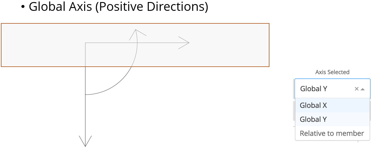
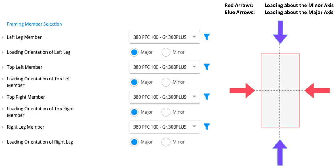
- Loading orientation refers to the orientation of the members individually with respect to the applied loads.
- About major axis - the members are connected such that the loads are applied perpendicular to the major bending axis of each specified section. Typically, the major axis is characterised by a higher Ix value
- About minor axis - the members are connected such that the loads are applied perpendicular to the minor bending axis of each specified section. Typically, the minor axis is characterised by a lower Ix value
Frame type selection: Custom vs. flat/monoslope vs. Truss Analysis Wizard
Choose the frame type from the dropdown that matches the actual structural system:- Flat / Monoslope / Gable / Custom (portal frame) — for moment frames with rigid beam-column connections. A simple moment frame with no internal ties should use flat/monoslope, not Custom.
- Webs / Ties / Braces appear in the Portal Frame Analysis calculator when you select a truss-type portal assembly (for example, multi-gable with roof ties). For a pure truss (no portal legs), use the Truss Analysis Wizard instead. If you expected a simple moment frame and are seeing web/tie/brace member categories, switch the portal frame type away from a trussed assembly — or open the Truss Analysis Wizard if that is the system you are modelling.
Single-storey scope and multi-storey workaround
The Portal Frame Analysis calculator models a single 2D frame (one storey height). There is no storey-count or multi-storey stack input. For a two-storey (or taller) moment frame, analyze each storey as its own Portal Frame calculation, using boundary conditions at the intermediate floor that represent continuity between storeys — typically a fixed base and matching column-top conditions carried forward as reactions on the storey above. Design each column and beam for the governing storey.Troubleshooting: “Solver validation failed. This probably means that your structure is unstable.”
This message means the structure is mechanically unstable — the model has a rigid-body degree of freedom that cannot be resolved. Common causes in a portal frame:- A pin support inadvertently set free in one translation direction.
- A moment-tie at mid-column accidentally releasing a rotational DOF.
- An element with both ends pinned creating a mechanism.