What it calculates
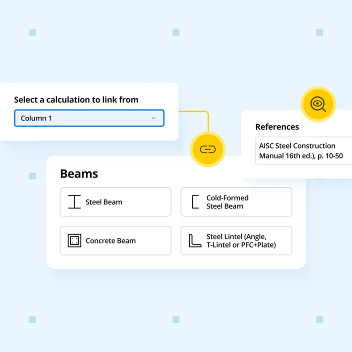
Column loads link directly from the calculations above, so changes propagate to the footing automatically. Design isolated spread footings to ACI 318-19 per IBC 2021. Results cover bearing capacity under service loads, flexural design, one-way shear, two-way (punching) shear, and development lengths.
Who uses this calculator
US structural engineers designing spread (pad) footings to IBC 2021, including foundations in high-wind areas or with lightly-loaded columns where uplift governs. Column loads link from the connected column calculation above, so bearing, flexure, and shear update automatically. For 2024 IBC projects, use the IBC 2024 edition.
Verify foundation resistance against upward forces with vertical restraints set as restrained or unrestrained. The uplift utilization summary replaces blunt uplift-fail messages with a clearer assessment, and covers bearing capacity, flexure, one-way and punching shear, and development lengths in one workflow.
How it calculates
The Spread Footing (IBC 2021) calculator designs isolated rectangular spread footings to ACI 318-19 as referenced by IBC 2021, with ASD and LRFD load combinations from ASCE 7-16 (Ch. 2). Service loads govern soil bearing and stability; factored loads govern the reinforced-concrete strength design. It handles concentric and eccentric (moment) loading and checks the full set of geotechnical and concrete limit states.
Bearing pressure and stability
Service-level column loads are combined through the ASCE 7-16 ASD combinations and resolved into a soil bearing pressure profile under the footing. Under moment, an iterative procedure covers the partial-contact (Zone 2) eccentricity case where part of the footing lifts off the soil:
utilization = q_max / q_allow ≤ 1.0
where q_allow is the allowable gross bearing capacity. Overturning and sliding are checked as factors of safety against user-set minimums:
FS_overturning = M_resisting / M_overturning ≥ FS_min
FS_sliding = (mu × N) / V ≥ FS_min
both evaluated on the X and Y axes.
Uplift safety factor
Net uplift from wind or seismic combinations is resisted by the footing and soil self-weight:
FS_uplift = W_resisting / T_net ≥ FS_min
The vertical restraint is set as restrained or unrestrained, and the column self-weight is not counted in the uplift resistance.
Flexural capacity (ACI 318-19, Cl. 22.2)
Factored bending moments at the face of the column are computed on each axis and compared to the reduced flexural capacity of the reinforced section:
utilization = M_u / (phi × M_n) ≤ 1.0
checked for X-axis and Y-axis bottom reinforcement. Where the bottom bars cannot develop, the calculator also evaluates whether a plain-concrete section passes. Negative bending (top reinforcement) capacity is checked on both axes for uplift or eccentric cases.
One-way (beam) shear (ACI 318-19, Cl. 22.5)
One-way shear demand is taken at a distance d from the column face and compared to the concrete shear strength (no shear reinforcement is assumed):
utilization = V_u / (phi × V_c) ≤ 1.0
Two-way (punching) shear (ACI 318-19, Cl. 22.6)
Punching shear is checked on the critical perimeter located d/2 from the column face:
utilization = v_u / (phi × v_c) ≤ 1.0
with v_c taken as the governing of the code expressions (aspect ratio, perimeter ratio, and the base term).
Development of reinforcement (ACI 318-19, Cl. 25.4)
The required development length of the flexural bars is checked against the length available from the critical section to the bar end, applying the standard modification factors. Excess reinforcement area is credited to reduce the required length, and top-bar development is checked separately.
Column-footing interface bearing (ACI 318-19, Cl. 22.8)
Bearing stress where the column lands on the footing is compared to the concrete bearing capacity, which is increased by the square root of the ratio of the supporting area to the loaded area (capped per code). Bearing dowels are sized where the interface bearing is exceeded.
Assumptions
The column is centred on the footing and designed separately. Compression reinforcement is not counted in bending strength, and no shear reinforcement is considered. For steel base plates, only concrete bearing under concentric load is checked; eccentric (moment) interface bearing is verified separately. The column self-weight is not counted in the uplift check.