What it calculates
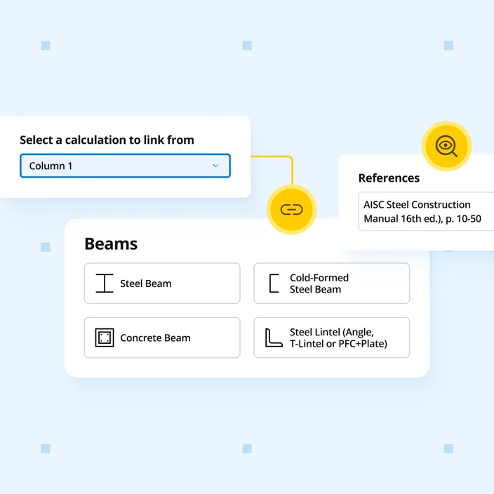
Design steel post sleeper retaining walls, with optional fence wind loading, to AS 4678:2002. Checks cover pile embedment in cohesive or cohesionless soil and steel post capacity, and sleeper loads link to a beam calculator.
Who uses this calculator
Australian engineers designing a post-and-sleeper retaining wall, often with a fence above, with steel posts embedded as concrete piles in cohesive or cohesionless soil. It sizes the pile embedment, checks the steel post capacity, and exports sleeper loads to a separate beam calculator.
How it calculates
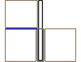
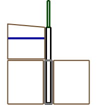
The Sleeper Retaining Wall calculator designs a post-and-sleeper wall. Vertical steel posts, embedded in concrete piles, resist lateral earth pressure and any wind load on a fence above. The sleepers spanning between posts are designed separately in a linked beam calculator. The calculation covers earth pressure, fence wind load, pile embedment strength, tip deflection, and steel post capacity.
Earth pressure and loads
Lateral earth pressure is estimated with the Rankine-Bell method per AS 4678:2002 (Figure E2), for granular or cohesive retained soil. The wall is conservatively assumed to be vertical. Pressure is built from the unit weight and friction angle of the retained soil, plus any groundwater height and surcharge. Surcharge must be at least the AS 4678 minimum, which the calculator sets from the wall height and backfill slope.
Material uncertainty factors, chosen by the retained soil condition, reduce the friction angle and cohesion for strength and serviceability. Retained soil cohesion can be included only for flat walls up to 1.5 m, in in-situ or Class I controlled fill, over cohesive foundation soil. The calculator uses a single load combination, with load factors on soil, water, surcharge and wind set in a table.
Wind loads on the fence
Where a fence sits above the wall, fence wind pressure comes from the AS 4055:2012 wind classification and the fence solidity ratio. The fence height and length also set the wind load. The resulting horizontal force is added to the demand on each post over its tributary width.
Pile strength design - cohesive foundation soil (Broms method)
For cohesive foundation soil, the short free-head pile embedment is designed by the Broms method from the undrained shear strength. That strength is reduced by a material uncertainty factor chosen by the foundation soil condition. The pile depth must be at least the calculated minimum, and less than 12 times the pile diameter.
Pile strength design - cohesionless foundation soil (IBC method)
For cohesionless foundation soil, the embedment is designed using the method of IBC 2018 Section 1807.3.2.1. The allowable lateral bearing pressure comes from the foundation soil classification you select. Because that method uses allowable stress loads, the horizontal force takes its own load factor, which defaults to serviceability values. Embedment is limited to 3.658 m (12 ft).
Tip deflection (cohesive foundation soil)
For cohesive foundation soil, the calculator checks deflection at the top of the post. Without pile rotation, this is the deflection from bending of the steel post, compared with a length-to-deflection ratio limit. With pile rotation included, it adds the Broms ground-level deflection from the subgrade reaction coefficient. The total is compared with your maximum allowed deflection. Deflection is not checked for cohesionless foundation soil.
Steel post capacity (AS 4100:2020)
The embedded steel post is checked to AS 4100:2020 for the governing horizontal forces. The calculator reports shear capacity, moment section capacity, and the shear-moment interaction. Full lateral restraint is assumed from the sleepers, and posts are assumed oriented so the major axis resists the soil loads.
Assumptions
The maximum retaining wall height is 3 m, and earthquake loads and liquefaction are not considered. The concrete pile is assumed not to crack or fail in bending. This holds where the steel post is embedded to full depth, but the user should verify it. Group effects for embedded piles are ignored, and the sleeper is designed in a separate, linkable beam calculator.