What it calculates
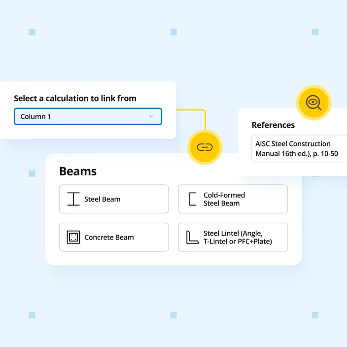
Post and column loads link directly from the calculations above, so changes propagate to the footing automatically. Design pier, pole, and deck-post footings to ACI 318-19 per IBC 2024. Results cover lateral embedment, vertical bearing, compression-bending interaction, shear, and uplift with skin friction resistance below the active soil zone.
Who uses this calculator
US structural engineers embedding pier, pole, and deck-post footings to the current IBC 2024 code, where lateral loads and uplift govern the embedment depth. Post axial and lateral reactions link from the connected column or deck-beam calculation above, so embedment, bearing, and uplift checks update automatically when loads change.
How it calculates
The Pole Footing (IBC 2024) calculator designs plain (unreinforced) concrete pier, pole, and deck-post footings to ACI 318-19 under IBC 2024, with ASD and LRFD load combinations from ASCE 7-22 (Ch. 2). The pier is assumed to be continuously restrained against buckling by the surrounding soil, so unbraced-length effects are neglected in the concrete compression checks.
Lateral embedment (IBC 2024, Cl. 1807.3)
The governing check for pole footings is the embedment depth needed to resist lateral load without excessive rotation. The IBC 2024 method evaluates the lateral soil-bearing pressure at one-third of the embedment depth and at the full depth:
- S_(1/3) - lateral soil stress at one-third of the embedment depth
- S_d - lateral soil stress at the full embedment depth
utilization = S_d / S_allow ≤ 1.0
For nonconstrained posts (free to rotate at grade) the required embedment is solved from moment equilibrium; a constrained post (braced at grade) permits a shorter depth.
Vertical bearing
Gross vertical bearing pressure is the total downward service load divided by the pier base area:
utilization = q_gross / q_a ≤ 1.0
Compression and bending capacity (ACI 318-19, Ch. 21)
The pier is checked as a plain concrete member under combined axial load and moment. Nominal moment capacity is evaluated on the tension and compression faces and combined with the compression capacity:
utilization = (P_u / (phi × P_n)) + (M_u / (phi × M_n)) ≤ 1.0
with phi = 0.60 for plain concrete in combined loading.
Shear capacity (ACI 318-19, Ch. 21)
One-way shear demand is compared to the plain-concrete shear strength:
utilization = V_u / (phi × V_c) ≤ 1.0
Uplift and downward safety factors
Uplift from wind or seismic is resisted by self-weight plus skin friction below the active soil movement zone:
FS_uplift = (W_pier + W_soil + f_s × A_skin) / T_net ≥ FS_min
A downward capacity check confirms the pier and bearing soil carry the maximum compressive service load:
FS_down = R_down / P_max ≥ FS_min
The active (movement) zone depth is a user input, so skin friction acts only below it. The wall or post self-weight above is not counted in the uplift resistance.
Concrete bearing at the post interface (ACI 318-19, Cl. 22.8)
Bearing stress where the post or bracket lands on the pier is compared to the plain-concrete bearing capacity. This check governs when concentrated loads transfer from a steel post base or bracket into the top of the pier.
Assumptions
The post is centred on a prismatic pier and designed separately. The footing is unreinforced (plain) concrete. Per IBC 2024 Cl. 1807.3, embedded posts are not used to provide lateral support for materials such as plaster, masonry, or concrete unless separate bracing is provided. Pier deflection and movement, where applicable, are checked separately.