

What it calculates
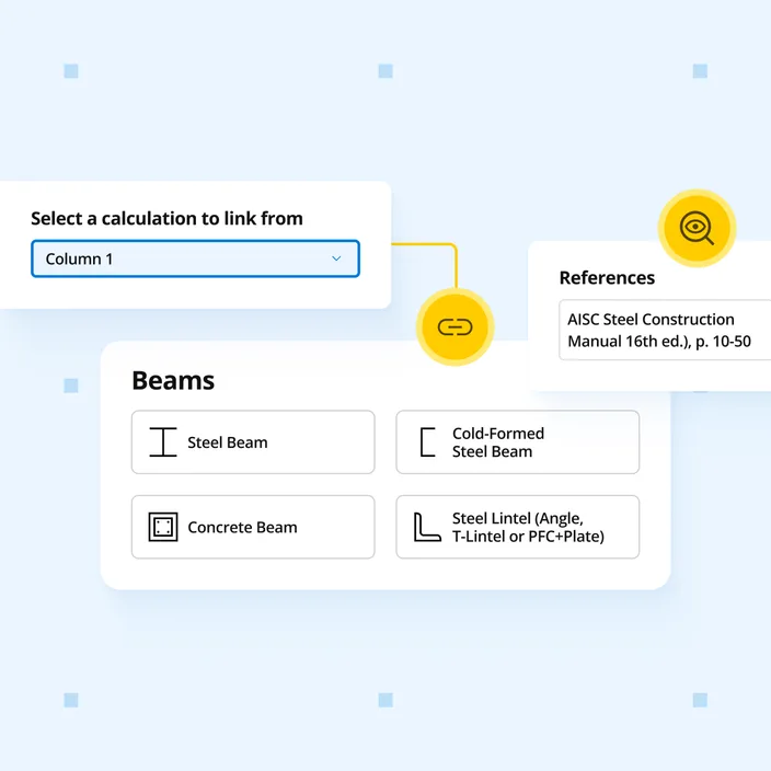
Beam reactions link to the columns and footings below, so load changes propagate downstream automatically. Design steel beams to AISC 360-16 ASD with multiple supports and loads. Floor- and roof-beam presets cut repetitive entry.
Who uses this calculator
Beam reactions link to the columns and footings below, so load changes propagate downstream automatically. Design steel beams to AISC 360-16 ASD with multiple supports and loads - floor- and roof-beam presets cut repetitive data entry for common configurations. For new work, use the AISC 360-22 ASD version.
How it calculates
The Steel Beam (ASD, AISC 360-16) calculator designs steel beams using Allowable Strength Design per AISC 360-16. Demands from ASD load combinations are compared to allowable strengths using the ASD safety factor Omega. Checks cover section classification, flexure, shear, and deflection.
Structural analysis
A finite element solver computes moment, shear, reactions, and deflections for each load combination. Loads can be distributed, line, point, or moment loads. Default ASD combinations are generated automatically, for example D + L, D + 0.75L + 0.75S and 0.6D + 0.6W. Project settings can change this list.
Section classification (AISC 360-16, B4)
Flange and web slenderness ratios are compared to the compact and noncompact limits (lambda_p and lambda_r) for the selected section. This determines whether the section is compact, noncompact, or slender, which governs the flexural capacity calculation path.
Flexural capacity (AISC 360-16, Chapter F)
Allowable bending strength is M_n / Omega_b, where Omega_b = 1.67. M_n is the lowest of the yielding, local buckling and lateral-torsional buckling (LTB) limits that apply:
- Yielding: for strong-axis bending, M_n = M_p = F_y × Z_x. For weak-axis bending of I-shapes and channels, M_p is the lesser of F_y × Z_y and 1.6 F_y × S_y.
- Local buckling: flange local buckling reductions apply to noncompact and slender flanges. Web local buckling is checked for HSS.
- LTB: M_n based on the unbraced length L_b relative to L_p and L_r. Moment gradient factor C_b applies to every shape except tees and double angles. Unbraced lengths come from the supports and your bracing inputs.
utilization = M_a / (M_n / Omega_b) ≤ 1.0
Positive and negative bending are checked separately. Tees, double angles and single angles get a separate capacity for each direction, since it depends on which side is in compression.
Shear capacity (AISC 360-16, Chapter G)
Allowable shear strength is V_n / Omega_v, with V_n = 0.6 F_y A_w C_v. For W, M and S shapes bent about the strong axis with h/t_w below 2.24 sqrt(E/F_y), C_v1 = 1.0 and Omega_v = 1.50. Other I-shapes and channels bent about the strong axis use C_v1 from web slenderness with Omega_v = 1.67. HSS, tees, angles and weak-axis bending use C_v2 with Omega_v = 1.67.
utilization = V_a / (V_n / Omega_v) ≤ 1.0
Deflection checks
Three deflection limits are tracked, each checked span by span:
- Instantaneous deflection - from live, roof live, snow and 0.42W cases, compared to the lesser of L/n and an absolute limit (defaults L/360 and 2 in)
- Long-term deflection - checked against its own limit (default L/240) and reported when it is more critical than the instantaneous check
- Simplified DL+(LL or SL) deflection - default combination D + L + Lr, limit L/240 by default
Each span reports its deflection, limit and L/ ratio. Cantilever limits use twice the cantilever length by default.
Assumptions
Axial load is assumed negligible. Members are straight and prismatic (not tapered). Inclined beams are supported but axial force is not checked and must be verified separately by the engineer.