What it calculates
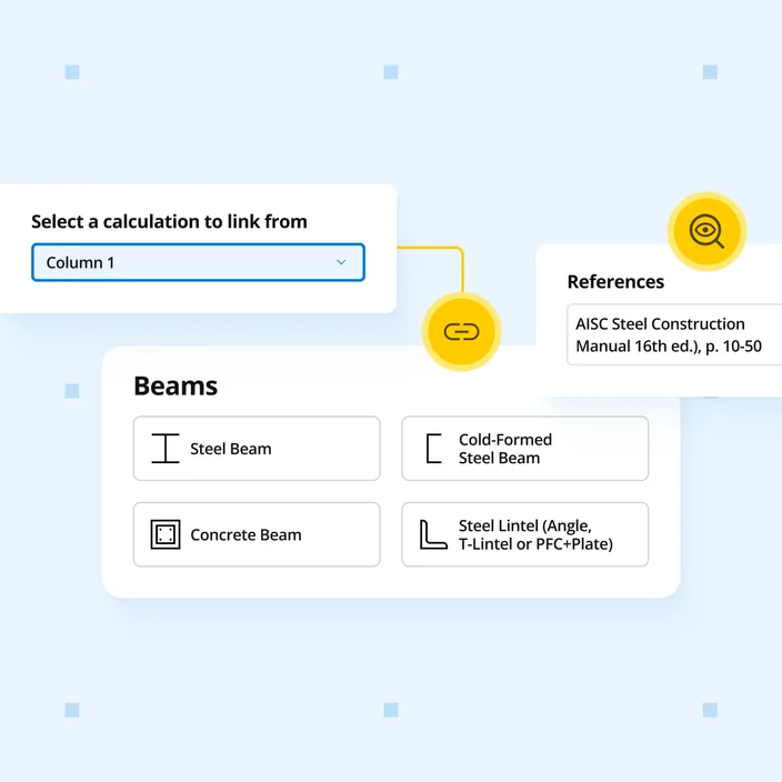
Beam reactions link to connected column and footing calculations automatically. Design rectangular concrete beams to Eurocode EN 1992-1-1:2004 with unlimited supports and loads, customisable reinforcement, and FEA-based analysis.
Who uses this calculator
Engineers designing rectangular reinforced concrete beams to Eurocode 2, when you need continuous members with custom reinforcement layouts rather than a single simply supported span. Beam reactions link to connected column and footing calculations, so changing a load once updates the whole load path.
How it calculates
Structural model and load combinations
The beam is analysed with a finite element (FEA) model that accepts unlimited supports and loads, so simple, continuous, and cantilevered spans are all handled in one calculation. Applied actions follow EN 1991, and the calculator assembles ULS and SLS load combinations to EN 1990:2002 from the permanent, variable, and wind load cases you enter. Unfactored load analysis is carried out alongside the combined analysis so that serviceability effects can be assessed against the correct combination. The cross-section is assumed uniform along the full member length, and detailing requirements are checked separately.
Flexural design at the ultimate limit state
Bending is checked separately in the positive-moment (sagging) regions at midspans and the negative-moment (hogging) regions at supports, because reinforcement and effective depth differ between the two. You specify the number, size, and layer of the bottom and top bars, and the calculator computes the design moment resistance from the concrete compression block and the tension steel, using the design concrete compressive strength (governed by the partial factor for concrete and the long-term coefficient) and the design yield strength of the reinforcement. Each region reports utilisation = design moment / design moment resistance ≤ 1.0. Moment redistribution ratio factors can be applied per region to redistribute support and span moments within the limits permitted by Eurocode 2.
Shear design at supports
Shear is verified at the supports to EN 1992-1-1:2004 Cl 6.2 using the variable strut inclination method. You define the transverse reinforcement by stirrup size, longitudinal spacing, number of legs per bundle, and stirrup angle, and set the cotangent of the compression strut inclination. The calculator determines the design shear resistance from the shear reinforcement and the compression strut capacity, applies the strength reduction factor for concrete cracked in shear, and enforces the minimum shear reinforcement ratio. The governing check is design shear force / design shear resistance ≤ 1.0.
Crack control at the serviceability limit state
Crack control follows EN 1992-1-1:2004 Cl 7.3.2 and Cl 7.3.4. The calculator evaluates the calculated crack width against the maximum allowable crack width you specify, using the coefficient for bond properties, coefficients for crack spacing, and the time after which cracking is first expected. This confirms that the reinforcement arrangement controls cracking under service loads.
Deflection control
Deflection is assessed by direct calculation to EN 1992-1-1:2004 Cl 7.4.3 rather than by span-to-depth ratios. The calculator reports characteristic (irreversible), frequent (reversible), and quasi-permanent (long-term) deflections, each compared against its own limit, including an absolute deflection criterion where specified. Accounting for cracked or uncracked section behaviour, this gives three independent serviceability deflection checks so short-term and long-term response are both captured.