What it calculates
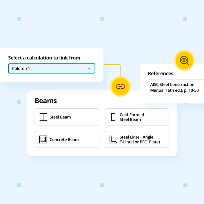
Column loads link from beam reactions above to footing calculations below automatically. Design rectangular concrete columns to Eurocode EN 1992-1-1:2004 with axial and biaxial bending checks, interaction diagrams, and second-order effects.
Who uses this calculator
Engineers sizing rectangular reinforced concrete columns to Eurocode 2, when axial load combines with biaxial moments and you need to check the result against a column interaction diagram. Axial loads link from the beams framing in above, so reactions update automatically when upstream loads change.
How it calculates
Structural model and load combinations
You define the column by its overall depth and width, total height, and effective buckling lengths about each axis. Applied actions follow EN 1991, and the calculator builds ULS and SLS load combinations to EN 1990:2002 from the permanent, variable, and wind load cases entered. An unfactored load analysis is carried out alongside the combined analysis so that serviceability effects are assessed under the correct combination. The design axial compression force and the design moments about the major and minor axes are then carried into the resistance checks.
Second-order effects
Slenderness and second-order effects are evaluated to EN 1992-1-1:2004 Cl 5.8.3 using the effective buckling lengths and the effective creep ratio. A minimum eccentricity is applied to the compression force about each axis, so that even nominally concentric columns carry a design moment. These effects amplify the first-order moments before the resistance checks, capturing the additional demand from column deflection under load.
Axial resistance and moment resistance
The maximum design axial compression resistance is computed to Cl 6.1 from the concrete compression block and the longitudinal reinforcement, using the design concrete compressive strength (governed by the partial factor for concrete and the long-term coefficient), the concrete ultimate compressive strain, and the design yield strength of the steel. The design moment resistance about each axis is found considering the coincident axial force, with a secant method solving the neutral axis depth so that internal forces balance the applied axial load. Each axis reports utilisation = design moment / design moment resistance ≤ 1.0.
Column interaction diagrams and biaxial bending
For each axis the calculator constructs a column interaction diagram, including the balanced-failure point, that plots the axial-moment capacity envelope of the section. The design demand is plotted against the envelope so the margin to capacity is visible directly. The two axes are then combined through the Eurocode 2 biaxial bending criterion (Cl 5.8.9), which raises the major-axis and minor-axis moment ratios to an exponent dependent on the axial load level and requires their sum to be ≤ 1.0.
Crack control
Crack control at the serviceability limit state follows EN 1992-1-1:2004 Cl 7.3.2 and Cl 7.3.4. The calculator evaluates the calculated crack width against the maximum allowable crack width, using the coefficient for bond properties, coefficients for crack spacing, and the strain in the extreme tensile fibre at first cracking. Separate secant-method solutions for the neutral axis depth at cracking are run for major-axis and minor-axis bending so cracking is assessed for both directions.