
Free beam calculator for Australian spans
How to use the free beam calculator
- 1
Enter beam geometry
Set the span length L in mm, elastic modulus E in MPa, second moment of area I_x in mm⁴, and cross-sectional area A in mm². Defaults are 2,000 mm and a 150 UB 14.0 at 200,000 MPa.
- 2
Set your supports
Add fixed, pinned or roller supports at any position along the beam. A support set away from the ends creates a cantilever, so overhanging and propped beams are entered the same way.
- 3
Apply loads
Add point loads in kN and distributed loads in kN/m. Unequal start and end magnitudes give a linearly varying load, and locations inside the span give a partial load.
- 4
Read the diagrams
Moment in kN·m, shear in kN and deflection in mm update instantly. Per-span moments and per-support reactions are tabulated below the diagrams.
About this calculator
Solve simple, continuous, cantilever and propped beams in metric units. Enter the span, section stiffness, supports and loads. A finite element solver returns bending moment, shear force and deflection along the full length. Per-span moments and per-support reactions are tabulated underneath. The analysis is code independent, so the same model holds under AS 4100, AS 1720.1 and AS 3600. Design checks against those standards need a free Calcs.com account.
Validated against:
- Connor (2013), Fundamentals of Structural Engineering, Example 3.13: a two-span beam with an internal hinge under opposing triangular loads. Solver moment agrees to within 0.3%, shear and support reactions match exactly.
Last reviewed
Inside the calculator
The Calcs.com beam calculator takes the geometry and loading of a beam and returns bending moment, shear and deflection diagrams, plus maximum demands, from a finite element analysis engine. Results update as you type. This page loads the calculator in metric units.
The solver works from the section stiffness you enter rather than a section type, so it handles any prismatic member: a rolled steel I-beam or RSJ, a timber joist, a concrete beam, or a built-up shape. Enter the area and second moment of area and the analysis is the same.
The analysis itself is code independent: it solves statics and stiffness, so the same model holds under AS, NZS, Eurocode, CSA and US standards. Design checks against a specific standard need a Calcs.com account, which adds design in steel, concrete and timber to AS 4100, AS 3600 and AS 1720.1.
The sheet is divided into three main sections:
- 'Key Properties', where you enter the beam geometry, the section stiffness and the support positions.
- 'Simple Loads', where you enter distributed and point loads.
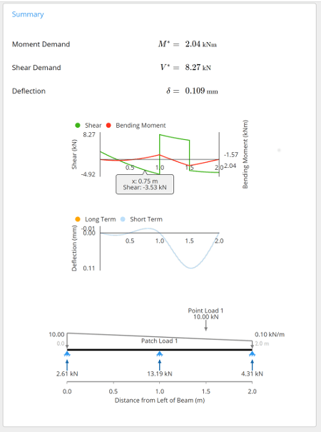
- 'Summary', which displays the governing demands and the diagrams, with per-span and per-support tables below.
A 'Comments' section is also included for the user to leave any specific design notes. Clicking on any of the input/property labels gives a descriptive reference explanation.
1. Input key properties
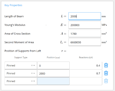
Type directly into the input fields. Length of Beam (L) is the total including all spans, not the length of one span. The defaults describe a 150 UB 14.0 in structural steel, so Area of the Cross-Section (A) and Second Moment of Area (I_x) both need replacing with the values for your own section. Units and defaults for every field are tabulated below.
The free tool has no section library built in, so A and I_x are typed in by hand. Read them off the section properties library for a standard rolled section, or compute them for a built-up shape with the free moment of inertia calculator.
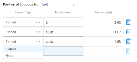
Position of Supports from Left takes any number of supports, each set to Fixed, Pinned or Roller at any position along the beam. A support placed away from 0 creates a cantilever at the left end, and one placed short of L creates a cantilever at the right, so simply supported, continuous, propped and overhanging beams are all entered the same way.
2. Input loads
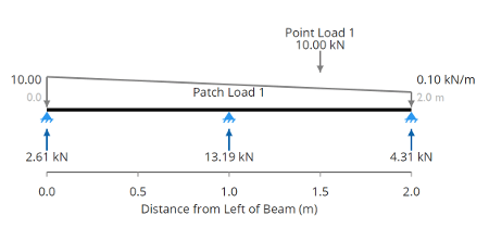
Distributed Loads take a start and end magnitude (kN/m) and a start and end location (mm). Equal magnitudes give a uniform load, unequal ones a linearly varying load, and locations inside the span give a partial load. The sheet opens with one distributed load of 0.1 kN/m rising to 1 kN/m across the full span.
Point Loads take a magnitude (kN) and a location (mm). Both tables accept a label per row, and both apply perpendicular to the beam. Axial, moment, linked and oriented loads are part of the full Calcs.com platform rather than the free tool.
3. Calculation summary outputs
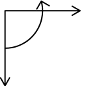
Four governing values head the summary. Moment Demand (M*) is the larger of the positive and negative bending moments. Deflection (δ) is positive downward and negative upward. Shear Demand (V*) and Maximum Reaction (R*) complete the set, with units for all four in the table further down.
Below the summary, Moment Demands Per Span breaks each span into positive, quarter-point, midpoint and negative moments, Deflection Per Span gives span length, span type and deflection, and the Support Demands table gives position, reaction, moment and shear at every support. Shear, moment and deflection diagrams plot along the full length, and hovering reads off the value at any point.
Worked example
The same analysis run start to finish, if you would rather watch it than read it:
A single simply supported 2,000 mm span of 150 UB 14.0, carrying a uniform 5 kN/m across its full length, returns:
- Moment demand M* of 2.5 kN·m, from wL² / 8
- Shear demand V* of 5 kN at each end, from wL / 2
- Deflection δ of 0.78 mm, from 5wL⁴ / 384EI
- Maximum reaction R* of 5 kN at each support
That is a span-to-deflection ratio of L/2,557, well inside a limit of the kind usually applied: L/250 would permit 8.00 mm over this span. Enter the same values above and the diagrams will match. Add a second support, or move one inboard, and the closed-form results stop applying: that is the point at which you need the finite element solver rather than a formula.
Finding a maximum span
The calculator solves a span you give it, so a maximum span is found by iterating. Fix the section and the load, then raise the beam length until either the deflection reaches the serviceability limit you design to, or the moment demand reaches the capacity of your section. L/360 and L/240 are the limits most commonly applied to floor and roof members respectively, though the governing value comes from your project requirements.
Bending stress is one step further on. The solver returns the moment, and dividing it by the elastic section modulus S gives the stress, where S is I_x divided by the distance to the extreme fiber. The free tool stops at the demand: checking that stress against an allowable value is a design check, and those need a Calcs.com account.
Inputs and outputs at a glance
| Quantity | Symbol | Unit | Default |
|---|---|---|---|
| Length of beam | L | mm | 2,000 mm |
| Young's modulus | E | MPa | 200,000 MPa |
| Area of cross-section | A | mm² | 1,780 mm² |
| Second moment of area | I_x | mm⁴ | 6,660,000 mm⁴ |
| Point load | P | kN | none |
| Distributed load | w | kN/m | 0.1 kN/m rising to 1 kN/m |
| Moment demand | M* | kN·m | calculated |
| Shear demand | V* | kN | calculated |
| Deflection | δ | mm | calculated |
| Maximum reaction | R* | kN | calculated |
Related calculators
Frequently asked questions
How far can a steel beam span?
What size beam do I need for a given span and load?
What size beam do I need to span 4 m?
How do you calculate a beam?
How do you calculate beam deflection?
What deflection limit should an Australian beam be checked against?
How do you get bending stress from the moment?
Can I use this beam calculator for RHS, UB and PFC sections?
What types of beams can this calculator analyze?
What sign conventions does the beam calculator use?
Is the beam calculator free to use?
What is locked behind a Calcs.com account?
Get more functionality with a free Calcs.com trial
Experience the full power of Calcs.com with a 14-day free trial.