What it calculates
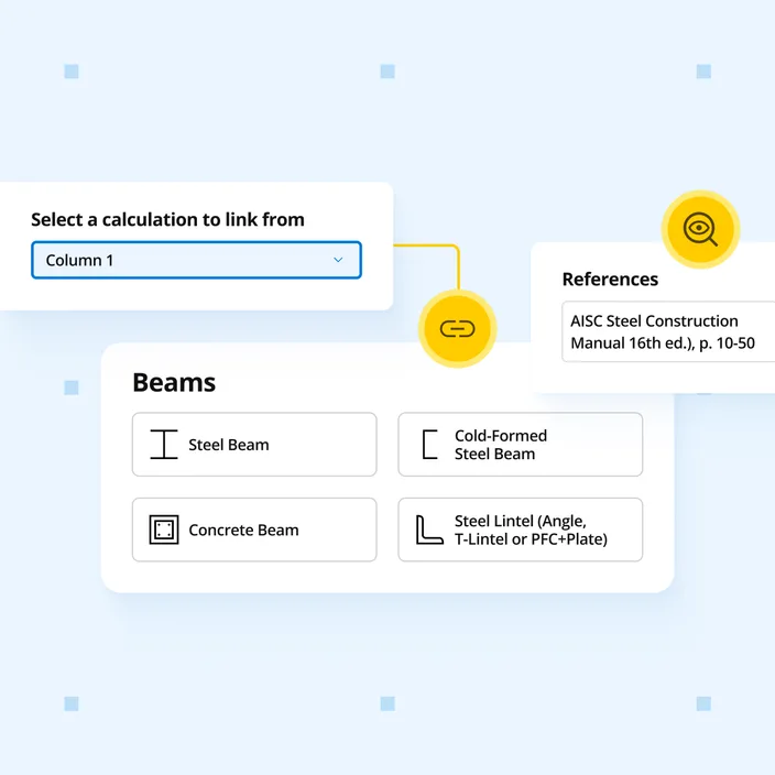
Beam reactions link to column and footing calculations automatically. Design steel beams to Eurocode 3 (EN 1993-1-1) with unlimited spans and loads - checks cover section capacity in bending, lateral torsional buckling, shear resistance, shear web buckling, and three EN 1990 deflection limits.
Who uses this calculator
Beam reactions link to your column and footing calculations automatically - change a load once and everything downstream updates. Design steel beams to Eurocode 3 (EN 1993-1-1) with checks for section bending capacity, lateral torsional buckling, shear resistance, shear web buckling (EN 1993-1-5), and three EN 1990 deflection limits.
How it calculates
Structural model and load combinations
The calculator models the steel beam as a one-dimensional element and computes bending moment, shear, and deflection diagrams under each EN 1990:2002 load combination. Loads are entered by type - permanent (G), variable (Q), wind (W), snow (S) - and the calculator generates governing ULS and three SLS combinations:
- Characteristic (irreversible): G + Q_k + psi_0 × other variable loads
- Frequent (reversible): G + psi_1 × Q_1 + psi_2 × other
- Quasi-permanent (long-term): G + psi_2 × Q
Cross-section classification (EN 1993-1-1:2005 Cl 5.5.2)
Before computing capacities, the calculator classifies the cross-section (Class 1 through 4) by checking the flange and web slenderness limits against epsilon = sqrt(235/fy). This governs whether the plastic, elastic, or effective section modulus is used for bending resistance.
Section bending capacity (EN 1993-1-1:2005 Cl 6.2.5)
Bending resistance M_c,Rd uses the plastic section modulus W_pl for Class 1 and 2 sections, the elastic section modulus W_el for Class 3, or the effective modulus W_eff for Class 4:
bending utilization = M_Ed / M_c,Rd ≤ 1.0
Shear resistance (EN 1993-1-1:2005 Cl 6.2.6)
The plastic shear resistance V_pl,Rd is computed from the shear area A_v (the web area for I-sections) and the yield strength fy. For webs with hw/tw ≥ 72 epsilon/eta, shear buckling governs and the check moves to EN 1993-1-5.
shear utilization = V_Ed / V_Rd ≤ 1.0
Shear buckling (EN 1993-1-5:2006 Cl 5.5)
For slender webs, shear buckling resistance V_b,Rd is computed using the contribution method - adding flange and web contributions. The web buckling coefficient k_tau depends on the panel aspect ratio a/hw between transverse stiffeners. The combined bending-and-shear interaction is then checked per EN 1993-1-1:2005 Cl 7.1 Eq 7.1.
Lateral torsional buckling (EN 1993-1-1:2005 Cl 6.3.2.1)
LTB resistance M_b,Rd is computed from the critical elastic moment M_cr and the reduction factor chi_LT. The relative slenderness lambda_LT is derived from M_cr, which accounts for the unbraced length, moment gradient, and section properties (I_w, I_T, I_z, EI). The reduction factor chi_LT reduces the cross-section moment resistance based on the imperfection factor for the LTB buckling curve applicable to the section.
LTB utilization = M_Ed / M_b,Rd ≤ 1.0
Deflection checks (EN 1990:2002 Cl 6.5.3)
Three independent deflection limit states are verified per span, using the characteristic, frequent, and quasi-permanent serviceability combinations respectively. Each is checked against a user-defined span/n ratio and an optional absolute limit in mm.
Load linking
Support reactions are exported as linked outputs. Connected column and footing calculations placed downstream in the same project receive updated reactions automatically whenever the beam inputs change.